CMC Airmaster S1 Manual

C.M.C. n.v. - Airmaster S1 installation guide – V1.2 – MANY0402A.00
MANY0402A.00
Airmaster S1 hardware installation guide
Version 1.2
© Compressor & Machine Controls n.v. 2001-2004
safety warning!
Do not operate the Airmaster S1 until you and all personnel concerned have read
and understood this installation guide.
Important notes
Installation and startup may only be done by trained personnel according to safe
engineering practices and with the observance of all relevant local health and safety
requirements and regulations.
A requirement of fault-free operation and fulfillment of any rights to claim under
guarantee is that the documentation is observed. In case of doubt please contact CMC.
This document could be subject to changes. Please contact our factory in case of doubt
in order to ensure that you have received the latest version.
Signs:
Hazardous or harmful situation
Possible consequences: Slight or minor injuries.
Possible damage to the unit and the
environment.
Electrical hazard:
Possible consequences: Severe or fatal injuries
Specific for the American (US) market
UL
Page 1 of 35

C.M.C. n.v. - Airmaster S1 installation guide – V1.2 – MANY0402A.00
Table of contents
1. Introduction.................................................................................................................................4
2. Models.........................................................................................................................................5
2.1 Basic versions ....................................................................................................................5
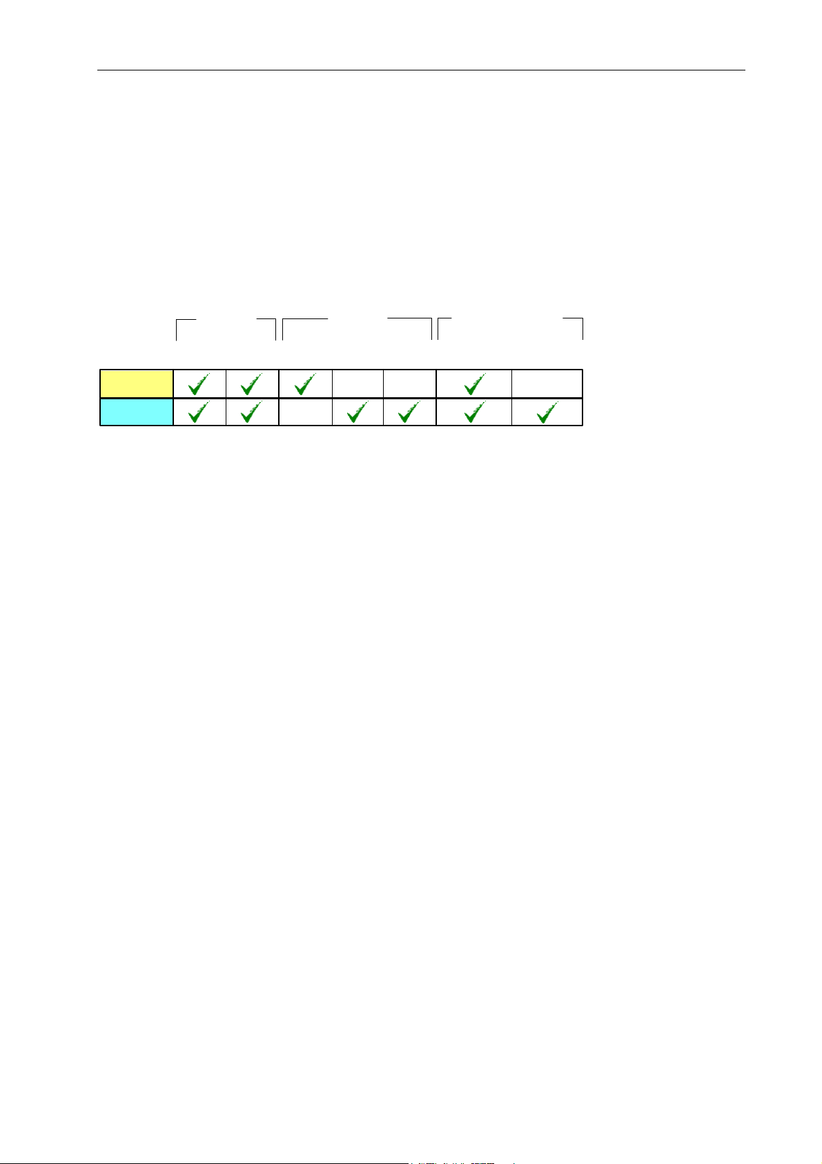
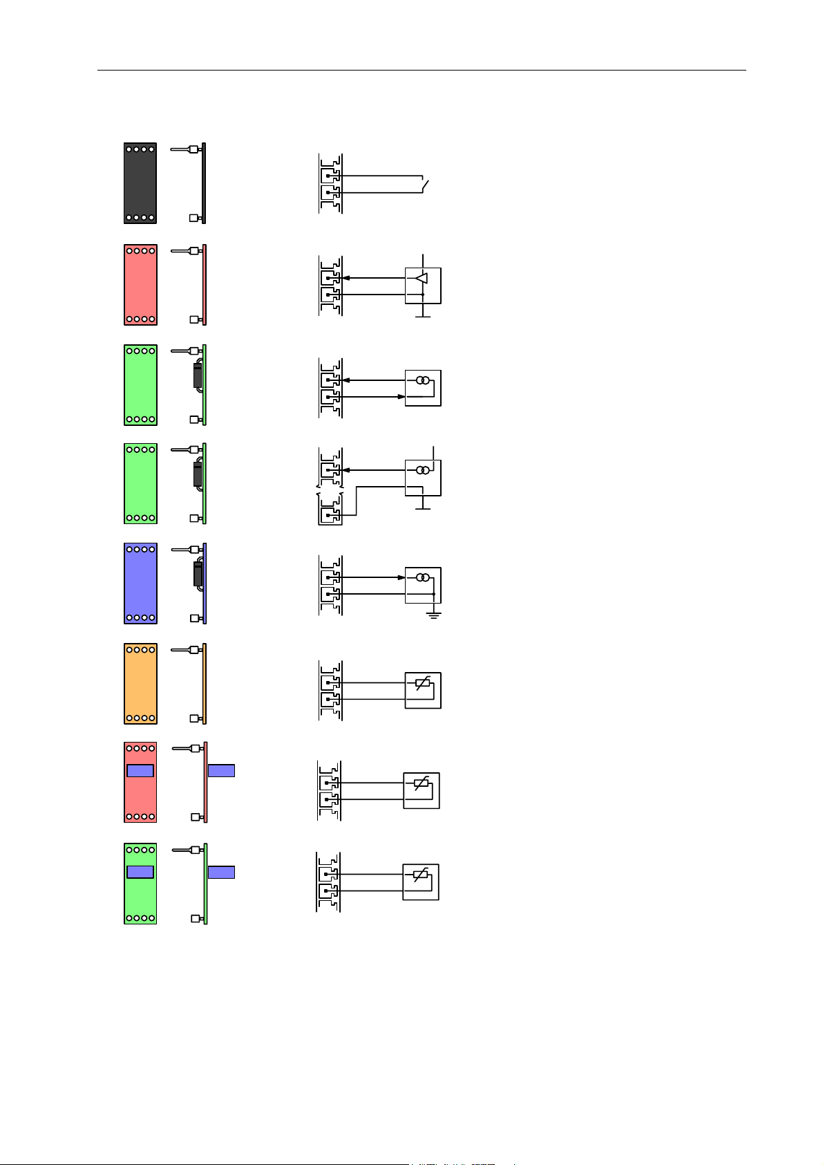
2.2 Analog conditioning modules...........................................................................................6
3. Technical specifications..............................................................................................................7
3.1 General technical data......................................................................................................7
3.2 Temperature range............................................................................................................7
3.3 Resistance to vibration and shock ..................................................................................8
3.4 Protection degree ..............................................................................................................8
4. Safety ..........................................................................................................................................8
5. Electromagnetic compatibility....................................................................................................9
6. Installation.................................................................................................................................10
6.1 Cable connector types ....................................................................................................10
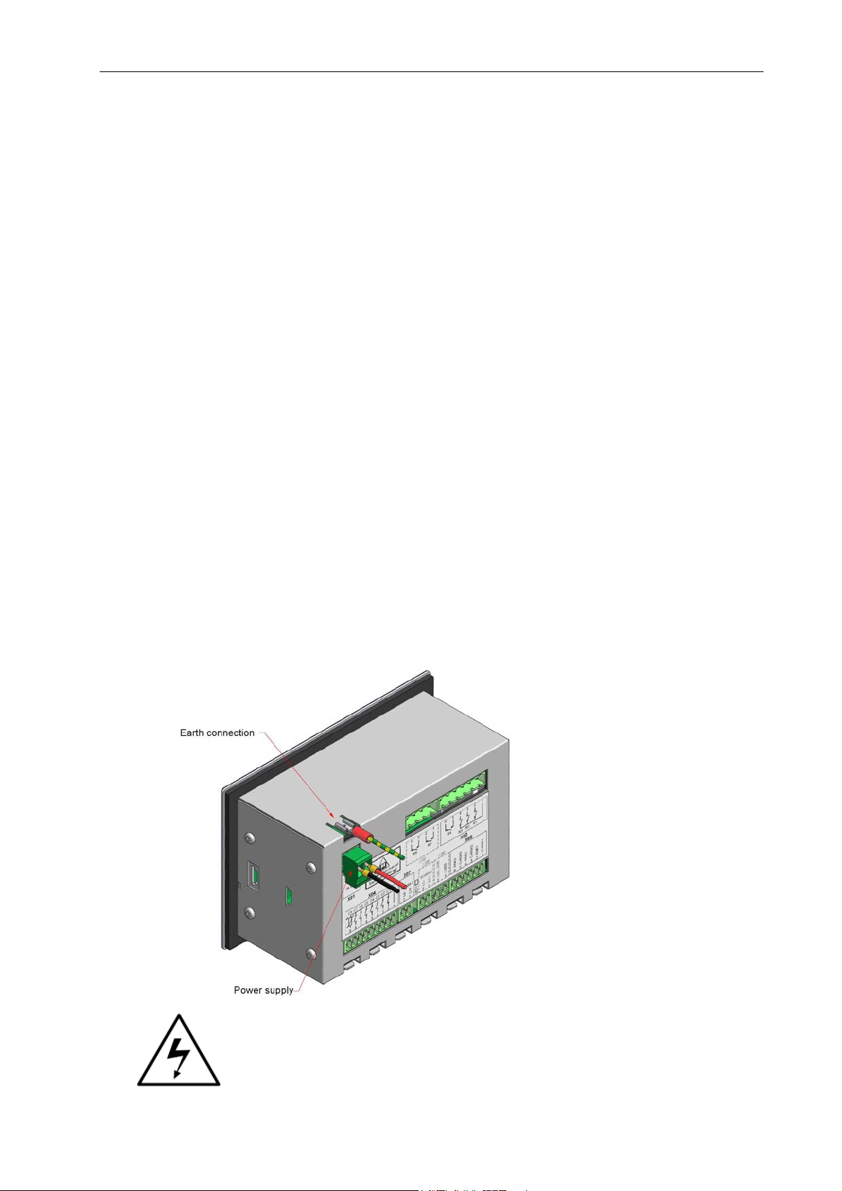
6.2 Power supply and fusing ................................................................................................10
General..................................................................................................................................11
For the American market (UL).............................................................................................11
For the European market (CE)..............................................................................................12
6.3 Analog inputs....................................................................................................................13
6.3.1 ACM type 1: digital input on analog connector...........................................................13
6.3.2 ACM type 2: 0-10Vdc voltage input ...........................................................................13
6.3.3 ACM type 3: 4-20mA input (standard)........................................................................14
6.3.4 ACM type 4: 4-20mA earth referenced (special type).................................................14
6.3.5 ACM type 5: KTY temperature sensor (-10…+132 deg C).......................................15
6.3.6 ACM type 5: RTD temperature sensor (-40…+150 deg C) .......................................15
6.3.7 ACM type 6: PT100 temperature sensor (-50…+250 deg C)......................................15
6.3.8 ACM type 7: PT1000 temperature sensor (-50…+250 deg C)....................................16
6.4 Digital inputs.....................................................................................................................17
6.4.1 The emergency stop contact input ...............................................................................18
6.4.2 The contact inputs........................................................................................................18
6.4.3 The PTC input..............................................................................................................18
6.5 Relay outputs ...................................................................................................................19
6.6 analog output (optional)..................................................................................................21
6.7 Communication ................................................................................................................21
6.7.1 RS485 port1 (standard)................................................................................................21
6.7.2 RS485 port2 (option) ...................................................................................................21
7. Mounting of the Airmaster S1 ..................................................................................................22
8. Putting into operation................................................................................................................23
9. Configuration............................................................................................................................23
10. Adjusting.................................................................................................................................24
11. Trouble shouting.....................................................................................................................24
Appendix 1: Dimensions and mounting of the S1 controller .......................................................25
Appendix 2: connectors for machine wiring.................................................................................29
Connector X01: Supply .........................................................................................................30
Connector X02: relays (optional) .........................................................................................30
Connector X03: relays...........................................................................................................30
Connector X04: digital inputs ...............................................................................................31
Connector X05: analog inputs..............................................................................................31
Page 2 of 35

C.M.C. n.v. - Airmaster S1 installation guide – V1.2 – MANY0402A.00
Connector X06: Analog output (optional) ...........................................................................31
Connectors X07: RS485-1....................................................................................................32
Connector X08: RS485-2 (optional) ....................................................................................32
Appendix 3: UL508 RATINGS / CONDITIONS ........................................................................33
Appendix 4: Display symbols.......................................................................................................34
Page 3 of 35

C.M.C. n.v. - Airmaster S1 installation guide – V1.2 – MANY0402A.00
1. Introduction
The Airmaster S1 is an industrial controller
This hardware installation guide is a guide for the hardware related items. Please read
the software specifications file for information on how to work with the unit.
The application area is restricted to machines that comply with the European machine
directive 89/37/EEC and the EMC directive 89/336/EEC. The application area is located
in electrical driven compressors and dryers in an industrial environment. Please contact
CMC for appliance in other machines.
The Airmaster S1 does not need to comply to the European Pressure Equipment
Directive 97/23/EC, because no parts are under pressure, and the Airmaster S1 is not a
safety component.
The Airmaster S1 is a component, which can’t operate without other components.
However, it is not a safety component, and it is not a machine.
The controller is to be used in a standard industrial environment. The controller may
only be used in places without an explosion risk. So it may never be used where
explosion-proof equipment is required. This controller may not be used for maritime
purposes. It may also not be used in any way as part of an assembly that could be used
for military or terrorist use.
The Airmaster S1 base unit without additional protection is to be used in areas of
pollution degree 1 or 2. Of course the user can add additional protection for higher
pollution degrees.
The installation of the controller must be made in accordance with the applicable
national and international standards and regulations.
For the American market UL508 is applicable, in accordance with the NFPA.
National and international directives and standards can change
in time. Please check them at a regular basis, and make
modifications to your equipment where this should be necessary.
Page 4 of 35

C.M.C. n.v. - Airmaster S1 installation guide – V1.2 – MANY0402A.00
2. Models
2.1 Basic versions
There are 2 basic versions available of the Airmaster S1. The following table indicates
the differences. The analog conditioning modules (see further) must be added to the
basic version.
4-20mA
4 x
Relay
8 x
Digital
3 x
Analogue RS485(1) RS485(2)
Communications
Inputs Outputs
S1 - 10
S1 - 20
S1 6 x
Relay
Model Reference Number: S1-xx-3yy
xx = configuration option; 10 or 20
yy = ACM selection
for example S1-10-350 =
AI1 = (3) 4-20mA (fixed)
AI2 = (5) KTY temperature
AI3 = (0) no ACM fitted
Page 5 of 35

C.M.C. n.v. - Airmaster S1 installation guide – V1.2 – MANY0402A.00
2.2 Analog conditioning modules
1
black
Digital
2
red
Voltage
0-10Vdc
3
green
4-20mA
Loop Powered
4
blue
4-20mA
Earth Referenced
5
copper
KTY Temperature
-10°C to +132°C
6
red
PT100 Temperature
-50°C to +250°C
7
green
PT1000 Temperature
-50°C to +250°C
3
green
4-20mA
Self Powered
AI
C
AI
C
+V
+V
AI
C
signal
+24Vdc
AI
A GND
10-32Vdc
signal
AI
C
signal
GND
AI
C
AI
C
AI
C
X01-16
+
-
+
-
+
-
A GND
A GND
A GND
A GND
A GND
Page 6 of 35

C.M.C. n.v. - Airmaster S1 installation guide – V1.2 – MANY0402A.00
3. Technical specifications
3.1 General technical data
Display Backlit LCD symbolic/numeric
Indicators 2, LED
Buttons 7, tactile response
Processor 16bit ST ST10R272
Flash EPROM 256 Kbytes (max.)
Non Volatile RAM 128 Kbytes (max.)
A to D Resolution 10bit (1/1024)
D to A Resolution 10bit (1/1024)
Supply input 24Vac (±20%) 24VA
Analog Inputs 3 standard
Digital Inputs 8 standard
Analog Outputs 1 optional
Relay Outputs 4 standard 6 maximum
(consult CMC for combination availability)
Construction Stainless steel front plate, steel anti-corrosion coated rear enclosure
Mounting 134mm x 84mm rectangle panel aperture, up to 2.5mm plate
Dimensions 144mm x 96mm x 62,8mm
Connections PCB mounted, Phoenix compatible
Conformity
US
C
3.2 Temperature range
Operating temperature 0°C to +55°C
Storage temperature -25°C to +75°C
Relative humidity at 40°C (non
condensing)
<95%
According to:
Operating tests at -10°C and +65°C
IEC 68-2-2 B Dry heat, 4 days
IEC 68-2-14 Nb Cyclic, 6hrs/cycle, 5 days
IEC 68-2-3 Ca Damp heat steady, 40°C, tbd R.H., 10 days
IEC 68-2-30 Db Damp heat cyclic, +50°C, variant 1, 2 cycles
IEC 68-2-1 A Cold, 4 days
Storage tests at -25°C and +75°C
IEC 68-2-1 A Cold 6 days
IEC 68-2-14 Na Change of temperature, 3hrs/temp, 2 cycles
IEC 68-2-2 B Dry heat 6 days
Page 7 of 35

C.M.C. n.v. - Airmaster S1 installation guide – V1.2 – MANY0402A.00
3.3 Resistance to vibration and shock
Operating
IEC 68-2-6 Fc Vibrating, 10-150Hz, 2g, 10sweeps/axis
Not operating (storage and handling)
IEC 68-2-6 Fc Vibrating, 10-150Hz, 1g, 5sweeps/axis
IEC 68-2-27 Ea Shock, 15g, 11ms, 3 shocks/axis
IEC 68-2-29 Bump, 10g, 6ms, 500 bumps / axis
3.4 Protection degree
Backside: IP20
Fascia: Designed to conform to a front fascia protection rating of NEMA12, IP65, when
installed correctly as detailed within an enclosure that conforms to this rating
4. Safety
The Airmaster S1 is a class I equipment in which protection against electric shock does
not rely on basic insulation only, but which includes an additional safety precaution in
that accessible conductive parts are connected to the protective earthing conductor in
the fixed wiring of the installation in such a way that they cannot become live in the
event of a failure of the basic insulation.
The Airmaster S1 must be earthed.
See drawing below (indicated with the yellow/green wire)
In the event that the Airmaster S1 is used to switch circuits
with a voltage of 42,4V peak or more, the danger of
electrocution exists and therefore protection measurements
have to be made for avoiding this situation.
Page 8 of 35

C.M.C. n.v. - Airmaster S1 installation guide – V1.2 – MANY0402A.00
If only low voltage limited energy circuits are connected to the Airmaster S1 it is still
necessary to earth the unit to fulfill the electromagnetic compatibility demands.
The enclosure must be earthed at all times.
Low voltage (low current, limited energy) wires must be separated from the power
wires.
CMC disclaims any warranty in case the Airmaster S1 has been opened or repaired by
an unauthorized person.
5. Electromagnetic compatibility
The enclosure is an important part of the protection of the electronics against
electromagnetic interference. Also the radiation of electromagnetic energy is shielded
by the enclosure. Therefore it is necessary to earth the enclosure with a very short wire
to the nearest earthed metal part. We advise a maximum length of 20cm. Use a
stranded wire with at least a section of 1.0mm2.
The electromagnetic compatibility of the unit cannot be guaranteed when the unit is
opened.
The use of shielded cables, especially for analog inputs and digital communication is
highly recommended in order to have a correct EMC installation.
It is the responsibility of the user to design the machine or installation to which this
equipment is to be fitted according to the rules of a good EMC installation.
Susceptibility IEC 801-2, EN61000-4-2 level 4, 8kV discharge
IEC 801-3, EN61000-4-3 level 3, 10V/m electric field
IEC 801-4, EN61000-4-4 level 4, 4kV transient on supply
IEC 801-5, EN61000-4-5 level 4, 2kV surge on supply (L-PE)
Emissions CISPR 22, EN55022 class A industrial radiated
CISPR 22, EN55022 class A industrial conducted
Page 9 of 35

C.M.C. n.v. - Airmaster S1 installation guide – V1.2 – MANY0402A.00
6. Installation
This part is necessary for the designer willing to use the Airmaster S1. It shows how an
S1 can be integrated into an electrical circuit. Chapter 8 “Putting into operation” gives
some directions that should be known in production. We strongly advise to use these
assembly instructions.
6.1 Cable connector types
The cable connector must match with the connectors populated on the Airmaster S1.
Please refer to appendix 2 for more information.
6.2 Power supply and fusing
Power supply and fusing is an important part of the installation. An AC voltage is
required. The maximum variation on the 24Vac is +-20%.
Only for use in Class 2 Circuits
The input voltage ratings for UL are:
Class 2 or LV/C, 24 V ac, 50/60 Hz
“The input circuitry of these devices have to be supplied from:
a) A Class 2 transformer in accordance with UL1585, or
b) An isolating device such that the maximum open circuit voltage
potential available to the circuit is not more than 28.8 Vac and the
current is limited to a value not exceeding 8 amperes measured
after 1 minute of operation, or
c) A suitable isolating source with a maximum open circuit voltage
potential of not more than 28.8 Vac in conjunction with a fuse in
accordance with UL248. The fuse shall be rated max. 1,6 A and be
installed in the input circuitry of the device in order to limit the
available current.”
UL
+V
24V
24VA
F1 (T)
L1
L3
T1 0V
V2
0V
1
2
F2 (T)
F1, F2: 1,6A T (Time lag, slow blow) fuses
Note: 24Vac controller power supply input must be floating, DO NOT EARTH
Page 10 of 35

C.M.C. n.v. - Airmaster S1 installation guide – V1.2 – MANY0402A.00
Connector X01
Pin Name Function
1 SUPPLY Supply input: AC
2 SUPPLY Supply input: AC
min typ max. dim
AC input voltage
AC input voltage 19.2 24 28.8 Vac
AC input frequency 50 60 Hz
Recommended 24Vac transformer 24 500 VA
Dropout at input 10 ms
General
The selection of the transformer must be in accordance with the applicable national and
international standards and regulations. Changes in time to these standards are always
possible. In case of doubt please do check them.
Examples:
For the American market (UL)
The selection of the transformer must be in accordance with the transformers
mentioned in the UL508(A) standard. This means that they have to be UL506 or
UL1585 or UL1310 approved (depending on the type).
The transformer or supply must be an UL Listed type or an UL recognized type.
An UL listed device in general does not need additional temperature
measurements for compliance, and is therefore recommended. An UL
recognized transformer needs additional temperature measurements by UL.
- 24Vac supply input:
A control transformer (UL506) in LV/C configuration or a Class 2 transformer
(complying with the requirements of UL 1585) must be used for the 24Vac power
input of the Airmaster S1. A not inherently limited transformer shall be provided
with additional over current protective devices in accordance with the
manufacturer’s instructions for the component.
- Digital outputs with relay contacts
The contacts of the Airmaster S1 relays must only be used in conjunction with a
control circuit transformer (Class 1, UL506), except if a voltage less than 30Vrms
is used with a limited energy rating. In the last case a Class 2 transformer is also
allowed.
The secondary circuit of the control transformer may NOT be grounded; else the
Airmaster S1 controller will be damaged.
Page 11 of 35

C.M.C. n.v. - Airmaster S1 installation guide – V1.2 – MANY0402A.00
A suitable UL508 branch circuit protection must be provided on the primary side
of the transformer. A supplemental fuse (in accordance with UL248 series) with a
rating of 1,6A ‘T’ type (slow blow) is obligated for the secondary side. In case of
doubt please contact the transformer supplier.
Please consult the text of the UL508A and/or UL508 standard for more
explanation regarding this item.
For the European market (CE)
The transformer or power supply must be in accordance with the current
applicable European directives (e.g. Low Voltage Directive and EMC directive).
This means that it must conform to the EN61558 standard (partly supersedes the
older EN60742 standard) for the particular application. Also applicable are
EN60204 (Safety of machinery - Electrical equipment of machines) and
EN60950. A CE marking must be on the device.
The Airmaster S1 is a class I equipment in which protection against electric
shock does not rely on basic insulation only, but which includes an additional
safety precaution in that accessible conductive parts are connected to the
protective earthing conductor in the fixed wiring of the installation in such a way
that they cannot become live in the event of a failure of the basic insulation.
In the case of a proper grounding or earth connection an isolating transformer
can be used. However, if the chance exists that the earth connection can be
disconnected when the equipment is under voltage, a safety-isolating
transformer must be used. Note that for EMC reasons an earth connection is
obligatory.
The transformer or supply must be suitable for use in a standard industrial
environment.
Page 12 of 35

C.M.C. n.v. - Airmaster S1 installation guide – V1.2 – MANY0402A.00
6.3 Analog inputs
The first analog input is a fixed 4..20mA input.
The two other analog inputs are definable using plug-in analog conditioning modules
(ACM’s). (Any combination is possible)
It is strongly recommended to use shielded cable for analog inputs. Use the fastons
near the analog inputs for connection of the cable shield. Shielding connections must
be as short as possible. Avoid long “pig tails”, as this will reduce EMC performance.
X05
A
I3
A
I2
A
I1
P_dP_I T_d
Connector X05 pin 1 C-ANA1 Analog 1 common
pin 2 ANA1 Analog 1 input
pin 3 C-ANA2 Analog 2 common
pin 4 ANA2 Analog 2 input
pin 5 C-ANA3 Analog 3 common
pin 6 ANA3 Analog 3 input
6.3.1 ACM type 1: digital input on analog connector
The analog inputs can act as a digital input when an ACM type 1 is used. The contact
is connected between the common (C) of the analog input, and the analog input. A
voltage free contact must be used.
6.3.2 ACM type 2: 0-10Vdc voltage input
A 0-10Vdc voltage can be used where the source is closely located to the basic
controller. Use earth-shielded cable no greater than 2m in lengths. Note that a 4-20mA
is a much better choice regarding EMI and distance.
+V means a positive voltage to analog ground (A GND). The signal voltage can be
different from the supply voltage of the external sensor.
Page 13 of 35

C.M.C. n.v. - Airmaster S1 installation guide – V1.2 – MANY0402A.00
6.3.3 ACM type 3: 4-20mA input (standard)
4..20mA loop powered
This configuration uses the available 24Vdc source on the base unit. No additional
power source is necessary. This configuration is recommended.
4..20mA self powered
In the self-powered configuration the sensor uses an external DC power supply source.
For reference with the supply, the GND must be connected to the housing of the
Airmaster S1.
6.3.4 ACM type 4: 4-20mA earth referenced (special type)
This ACM can be used with a special 4..20mA current sensor
(with GND connected to ground).
Page 14 of 35

C.M.C. n.v. - Airmaster S1 installation guide – V1.2 – MANY0402A.00
6.3.5 ACM type 5: KTY temperature sensor (-10…+132 deg C)
A KTY temperature sensor is a semiconductor sensor. The standard sensor type that is
used is the type KTY10-62 or KTY10-6 or KTY11-6 variant.
6.3.6 ACM type 5: RTD temperature sensor (-40…+150 deg C)
A RTD (resistance temperature detector) temperature sensor is a semiconductor
sensor.
6.3.7 ACM type 6: PT100 temperature sensor (-50…+250 deg C)
A PT100 temperature sensor can be connected to the base unit, but only for very short
distances (2 meters). If accurate measurements must be made it is much better to use
a PT1000 temperature sensor. You can run 10 times further with your cable for having
the same error due to the wire resistance as with PT100.
PT100 temperature sensors have a resistance varying with the temperature. When the
temperature is 0°C (32°F) the nominal resistance is 100 ohm. At 200,4°C this
resistance is raised to 176,0 ohm.
Use PT100 sensors with a mean temperature coefficient αof 0.003850 ΩΩ-1°C-1.In
case of doubt please contact your sensor supplier. (reference: IEC Publication 751)
The wires to a sensor must be as short as possible and with a big enough section in
order to reduce the wire resistance error.
The wires of a PT100 sensor of the same color have to be kept together if the sensor
has more than 2 wires.
Page 15 of 35

C.M.C. n.v. - Airmaster S1 installation guide – V1.2 – MANY0402A.00
Connect the shielding of the sensor cable to the earth faston connector of the S1 unit.
6.3.8 ACM type 7: PT1000 temperature sensor (-50…+250 deg C)
PT1000 temperature sensors have a resistance varying with the temperature. When the
temperature is 0°C (32°F) the nominal resistance is 1000 ohm. At 200,4°C this
resistance is raised to 1760 ohm.
Use PT1000 sensors with a mean temperature coefficient αof 0.003850 ΩΩ-1°C-1. In
case of doubt please contact your sensor supplier. (reference: IEC Publication 751)
The wires to a sensor must be as short as possible and with a big enough section, to
reduce wire resistance errors.
The wires of a PT1000 sensor of the same color have to be kept together if the sensor
has more than 2 wires.
Connect the shielding of the sensor cable to the earth faston connector of the S1 unit.
Page 16 of 35

C.M.C. n.v. - Airmaster S1 installation guide – V1.2 – MANY0402A.00
6.4 Digital inputs
There are 8 digital inputs on the S1 unit: 1 for the emergency stop button, 6 general
purpose and 1 PTC input.
Connector X04
PTC1
19
X04
C+
ES
C1 C
2
C3 C4 C5 C6 C7 C8
pin 1 C+ Common
pin 2 C1 Input 1
pin 3 C2 Input 2
pin 4 C3 Input 3
pin 5 C4 Input 4
pin 6 C5 Input 5
pin 7 C6 Input 6
pin 8 C7 Input 7
pin 9 C8 Input 8
Common Terminal
Voltage 24VDC
Sink Current up to 200mA
Digital Input 1 (Emergency Stop)
Sink Current 10mA max
Resistance closed contact < 3 ohm
Resistance open contact > 750 Kohm
Digital Inputs 2 to 7 (general purpose)
Sink Current 10mA max
Resistance closed contact < 13 Kohm
Resistance open contact > 750 Kohm
Digital Input 8 (PTC thermistor)
Sink Current 1.4mA
Resistance closed contact < 750 ohm
Resistance open contact > 4000 ohm
Conformity IEC 34-11-2, VDE 0660
Note: all resistance are inclusive the resistance of the cabling.
Page 17 of 35

C.M.C. n.v. - Airmaster S1 installation guide – V1.2 – MANY0402A.00
6.4.1 The emergency stop contact input
The contact, which is connected between the first digital input and the common digital
inputs supply terminal, is also feeding the internal relays of the Airmaster S1. As soon
as this contact opens, all relays are de-energized. In this manner, when an emergency
occurs, all outputs become non-active without intervention of the microprocessor or
software. This contact must be normal-closed, which opens in case of emergency stop.
Contactors, relays or other output devices connected to the
relay outputs of the Airmaster S1 must also be disconnected by
another contact on the emergency stop button.
Special precautions must be foreseen that no over voltage is
applied to the emergency stop contact input.
6.4.2 The contact inputs
The Airmaster S1 can read the status of all contact inputs. Over an open contact a
minimum voltage of 18Vdc is maintained. When the external contact is closed a
minimum current of 5mA runs through the contact. This is intended to prevent contact
oxidization errors.
6.4.3 The PTC input
The last contact input can be used to indicate the status of a Positive Temperature
Coefficient thermistor (PTC). The characteristic of the input is according to IEC 34-11-2,
VDE 0660.
Do not apply an external voltage on the PTC input, as
this will damage the unit.
The PTC input can also be used for switching contact inputs. If used in this way
attention to the type of contact must be made, as the closed circuit current is low and
may not penetrate oxidization. Use with gold flashed contacts in enclosed or sealed
devices.
Page 18 of 35

C.M.C. n.v. - Airmaster S1 installation guide – V1.2 – MANY0402A.00
6.5 Relay outputs
The Airmaster S1 has 6 relays.
X03
R1 R2 R3 R4 R5
EXAMPLE
R6
K1 K2 K3 S1
14
+VC
0VC
61
OPTIONAL
X02
Switching Voltage (max) 240Vac / 24Vdc
Continuous Current (max) 8Aac / 8Adc (resistive load) (*)
Breaking Capacity (max) 1800VA (cosØ=1) / 150W dc
Switching Rate 300 ops/min (no load)
30 ops/min. (rated load)
Mechanical Life 10M ops
Contact Life @ load 100K ops (cosØ=1)
Operating Time 10ms max
Release Time 10ms max
VDR Rating (R1 to 4) 300Vac / 385Vdc
Maximum current pin 1 12Aac or dc (15A peak for <3s)
for UL: 10A @ max. 240Vac
(*) See Appendix 3 for UL508 ratings.
Connector X03 pin 1 C-R1,2,3 R1,2 and 3 common
pin 2 NO-R1 R1 normally open
pin 3 NO-R2 R2 normally open
pin 4 NO-R3 R3 normally open
pin 5 NO-R4 R4 normally open
pin 6 C-R4 R4 common
Connector X02 (optional)
pin 1 NO-R5 R5 normally open
pin 2 C-R5 R5 common
pin 3 NO-R6 R6 normally open
pin 4 C-R6 R6 common
Page 19 of 35

C.M.C. n.v. - Airmaster S1 installation guide – V1.2 – MANY0402A.00
The normal open contacts can be used for voltages up to 240Vac or 24Vdc.
The minimum load is 100mA at a minimum switching voltage of 5Vdc.
Although the first 4 relays have VDR’s on board in order to reduce the spikes due to the
opening of the relay contacts, the customer must also use a snubber circuit in order to
reduce the spikes at the load side. For the other relays the same rule is applicable.
Do not exceed the maximum voltage and current.
In case of a non-resistive load on the relay contact, a
derating is necessary of the maximum current.
Page 20 of 35
Table of contents
Other CMC Industrial Equipment manuals
Popular Industrial Equipment manuals by other brands

Dungs
Dungs FRM-NOC 100 Series instruction manual

ProMinent
ProMinent DULCOLyse Original operating instructions

Promation Engineering
Promation Engineering P9-120N4-HR Installation & operation manual

Tescom
Tescom TC-5942B operating manual

MÄDLER
MÄDLER FS Mounting and operating instructions

Hypertherm
Hypertherm RS-485 Series Field Service Bulletin