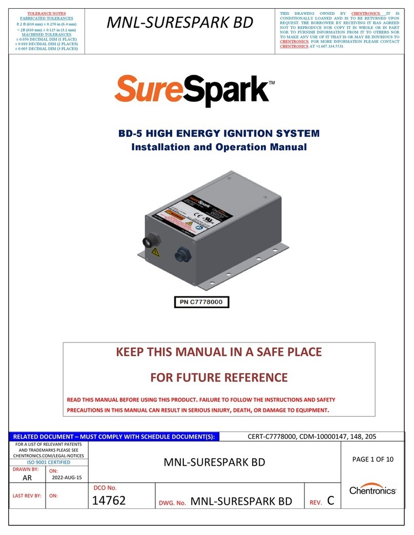
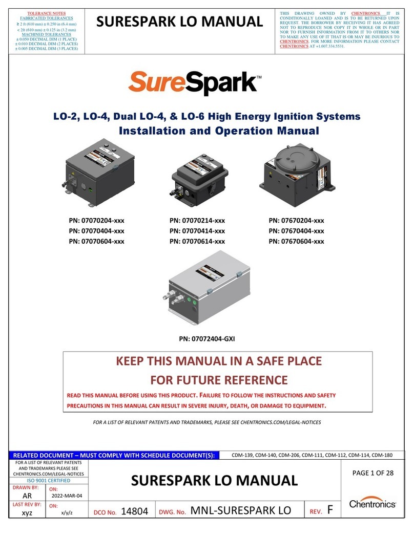
Chentronics SmartSpark 07000224-AZ User manual

RELATED DOCUMENT – MUST COMPLY WITH SCHEDULE DOCUMENT(S):
CERT-MNL-SMARTSPARK, CDM-10000125, CDM-10000127, CDM-10000171,
CDM-10000194, CDM-10000216
FOR A LIST OF RELEVANT PATENTS
AND TRADEMARKS PLEASE SEE
CHENTRONICS.COM/LEGAL-NOTICES
SMARTSPARK MANUAL PAGE 1 OF 14
ISO 9001 CERTIFIED
DRAWN BY:
AR
ON: 2022-FEB-10
LAST REV BY:
AR ON: 2020-APR-18
DCO No
.
14749
DWG. No.
MNL-07000224
REV.
J
THIS DRAWING OWNED BY CHENTRONICS. IT IS
CONDITIONALLY LOANED AND IS TO BE RETURNED UPON
REQUEST. THE BORROWER BY RECEIVING IT HAS AGREED
NOT TO REPRODUCE NOR COPY IT IN WHOLE OR IN PART NOR
TO FURNISH INFORMATION FROM IT TO OTHERS NOR TO
MAKE ANY USE OF IT THAT IS OR MAY BE INJURIOUS TO
CHENTRONICS. FOR MORE INFORMATION PLEASE CONTACT
CHENTRONICS AT +1.607.334.5531.
TOLERANCE NOTES
FABRICATED TOLERANCES
≥2 ft (610 mm) ± 0.250 in (6.4 mm)
< 2ft (610 mm) ± 0.125 in (3.2 mm)
MACHINED TOLERANCES
± 0.050 DECIMAL DIM (1 PLACE)
± 0.010 DECIMAL DIM (2 PLACES)
± 0.005 DECIMAL DIM (3 PLACES)
MNL-07000224
High Energy Ignition System
Installation and Operation Manual
Part Numbers:
07000224-AZ
07000224-AK
07000224-BZ
07000224-BK
KEEP THIS MANUAL IN A SAFE PLACE
FOR FUTURE REFERENCE
READ THIS MANUAL BEFORE USING THIS PRODUCT.FAILURE TO FOLLOW THE INSTRUCTIONS AND SAFETY
PRECAUTIONS IN THIS MANUAL CAN RESULT IN SERIOUS INJURY OR DEATH OR DAMAGE TO EQUIPMENT.

RELATED DOCUMENT – MUST COMPLY WITH SCHEDULE DOCUMENT(S):
CERT-MNL-SMARTSPARK, CDM-10000125, CDM-10000127, CDM-10000171,
CDM-10000194, CDM-10000216
FOR A LIST OF RELEVANT PATENTS
AND TRADEMARKS PLEASE SEE
CHENTRONICS.COM/LEGAL-NOTICES
SMARTSPARK MANUAL PAGE 2 OF 14
ISO 9001 CERTIFIED
DRAWN BY:
AR
ON: 2022-FEB-10
LAST REV BY:
AR ON: 2020-APR-18
DCO No
.
14749
DWG. No.
MNL-07000224
REV.
J
THIS DRAWING OWNED BY CHENTRONICS. IT IS
CONDITIONALLY LOANED AND IS TO BE RETURNED UPON
REQUEST. THE BORROWER BY RECEIVING IT HAS AGREED
NOT TO REPRODUCE NOR COPY IT IN WHOLE OR IN PART NOR
TO FURNISH INFORMATION FROM IT TO OTHERS NOR TO
MAKE ANY USE OF IT THAT IS OR MAY BE INJURIOUS TO
CHENTRONICS. FOR MORE INFORMATION PLEASE CONTACT
CHENTRONICS AT +1.607.334.5531.
TOLERANCE NOTES
FABRICATED TOLERANCES
≥2 ft (610 mm) ± 0.250 in (6.4 mm)
< 2ft (610 mm) ± 0.125 in (3.2 mm)
MACHINED TOLERANCES
± 0.050 DECIMAL DIM (1 PLACE)
± 0.010 DECIMAL DIM (2 PLACES)
± 0.005 DECIMAL DIM (3 PLACES)
MNL-07000224
Contents
1.0 Important Safety Information........................................................................................................... 3
2.0 System Specifications........................................................................................................................ 7
2.1 Description of Equipment ............................................................................................................. 7
2.2 General Arrangement ................................................................................................................... 7
2.3 Configurations:.............................................................................................................................. 7
2.4 Equipment Enclosure .................................................................................................................... 8
2.5 Equipment Conditions of Use ....................................................................................................... 8
2.6 Electrical Area Classification and Safety Markings ....................................................................... 8
2.7 System Electrical and Physical Specifications ............................................................................... 9
3.0 Installation Instructions .................................................................................................................. 10
3.1 Igniter Installation....................................................................................................................... 10
3.2 Input Power Cable Installation.................................................................................................... 10
3.3 Installing the Exciter on a Burner................................................................................................11
3.4 Equipment Earth Bond Location ................................................................................................. 11
3.5 System Schematic Diagram.........................................................................................................12
4.0 System Operational Inputs and Outputs.......................................................................................13
4.1 Applying Power to Equipment ....................................................................................................13
4.2 Firing the Igniter..........................................................................................................................13
4.3 System LED Indicator ..................................................................................................................14
5.0 Standard Components and Accessories.......................................................................................... 14
5.1 Standard System Components....................................................................................................14
6.0 Warranty Instructions ....................................................................................................................14
7.0 Technical Support...........................................................................................................................14

RELATED DOCUMENT – MUST COMPLY WITH SCHEDULE DOCUMENT(S):
CERT-MNL-SMARTSPARK, CDM-10000125, CDM-10000127, CDM-10000171,
CDM-10000194, CDM-10000216
FOR A LIST OF RELEVANT PATENTS
AND TRADEMARKS PLEASE SEE
CHENTRONICS.COM/LEGAL-NOTICES
SMARTSPARK MANUAL PAGE 3 OF 14
ISO 9001 CERTIFIED
DRAWN BY:
AR
ON: 2022-FEB-10
LAST REV BY:
AR ON: 2020-APR-18
DCO No
.
14749
DWG. No.
MNL-07000224
REV.
J
THIS DRAWING OWNED BY CHENTRONICS. IT IS
CONDITIONALLY LOANED AND IS TO BE RETURNED UPON
REQUEST. THE BORROWER BY RECEIVING IT HAS AGREED
NOT TO REPRODUCE NOR COPY IT IN WHOLE OR IN PART NOR
TO FURNISH INFORMATION FROM IT TO OTHERS NOR TO
MAKE ANY USE OF IT THAT IS OR MAY BE INJURIOUS TO
CHENTRONICS. FOR MORE INFORMATION PLEASE CONTACT
CHENTRONICS AT +1.607.334.5531.
TOLERANCE NOTES
FABRICATED TOLERANCES
≥2 ft (610 mm) ± 0.250 in (6.4 mm)
< 2ft (610 mm) ± 0.125 in (3.2 mm)
MACHINED TOLERANCES
± 0.050 DECIMAL DIM (1 PLACE)
± 0.010 DECIMAL DIM (2 PLACES)
± 0.005 DECIMAL DIM (3 PLACES)
MNL-07000224
1.0 Important Safety Information
Read All Instructions Before Using the Equipment
The instructions in this manual serve as a general guide. It is intended for use by qualified personnel with
knowledge of equipment of this type. It is not intended to cover all possible variations in equipment or to
provide for specific operating problems which may arise.
You are responsible for adhering to all warnings or cautions provided in this manual.
In addition to any general safety measures provided in this manual, you must comply with all national,
state, local, and company safety regulations.
Safety Symbols used in this manual comply with ISO 3864.
THESE SYMBOLS ARE USED TO ALERT YOU TO POTENTIAL PERSONAL INJURY HAZARDS.
OBEY ALL SAFETY MESSAGES THAT FOLLOW THESE SYMBOLS TO AVOID POSSIBLE INJURY OR DEATH.
Indicates a hazard with a high level of risk, which, if not avoided,
will result in death or serious injury.
Indicates a hazard with a medium level of risk, which, if not
avoided, could result in death or serious injury.
Indicates a hazard with a low level of risk, which, if not avoided,
will result in minor or moderate injury.

RELATED DOCUMENT – MUST COMPLY WITH SCHEDULE DOCUMENT(S):
CERT-MNL-SMARTSPARK, CDM-10000125, CDM-10000127, CDM-10000171,
CDM-10000194, CDM-10000216
FOR A LIST OF RELEVANT PATENTS
AND TRADEMARKS PLEASE SEE
CHENTRONICS.COM/LEGAL-NOTICES
SMARTSPARK MANUAL PAGE 4 OF 14
ISO 9001 CERTIFIED
DRAWN BY:
AR
ON: 2022-FEB-10
LAST REV BY:
AR ON: 2020-APR-18
DCO No
.
14749
DWG. No.
MNL-07000224
REV.
J
THIS DRAWING OWNED BY CHENTRONICS. IT IS
CONDITIONALLY LOANED AND IS TO BE RETURNED UPON
REQUEST. THE BORROWER BY RECEIVING IT HAS AGREED
NOT TO REPRODUCE NOR COPY IT IN WHOLE OR IN PART NOR
TO FURNISH INFORMATION FROM IT TO OTHERS NOR TO
MAKE ANY USE OF IT THAT IS OR MAY BE INJURIOUS TO
CHENTRONICS. FOR MORE INFORMATION PLEASE CONTACT
CHENTRONICS AT +1.607.334.5531.
TOLERANCE NOTES
FABRICATED TOLERANCES
≥2 ft (610 mm) ± 0.250 in (6.4 mm)
< 2ft (610 mm) ± 0.125 in (3.2 mm)
MACHINED TOLERANCES
± 0.050 DECIMAL DIM (1 PLACE)
± 0.010 DECIMAL DIM (2 PLACES)
± 0.005 DECIMAL DIM (3 PLACES)
MNL-07000224
HAZARDOUS VOLTAGE
The equipment contains a High Energy Ignition System, which contains DANGEROUS AND POTENTIALLY
LETHAL VOLTAGE. To avoid the risk of serious injury from electric shock, always follow the safety
precautions listed below:
Disconnect power before servicing the equipment.
Ensure the equipment is appropriately bonded to earth before use. See Section 4.4 regarding equipment
earth bond locations.
Do not join or separate any connection to the equipment when the equipment is energized.
Do not apply power to the equipment without an igniter attached.
Keep the igniter firing end away from all personnel and flammable material.
The equipment must be installed and serviced by qualified personnel in accordance with this manual and
applicable local and national codes, standards, and ordinances.
The equipment is not field-repairable. Do not attempt to disassemble or repair the equipment.
Do not connect, disconnect, or service the equipment if an Explosive Atmosphere may be present
The equipment must be installed and serviced by qualified personnel in accordance with applicable local
and national codes, standards, and ordinances.
The equipment’s enclosure may not be modified.
The equipment is not user/field repairable and must be returned to the manufacturer for evaluation in
the event of an equipment malfunction.
Substitution of components may impair suitability for ATEX Zone areas.

RELATED DOCUMENT – MUST COMPLY WITH SCHEDULE DOCUMENT(S):
CERT-MNL-SMARTSPARK, CDM-10000125, CDM-10000127, CDM-10000171,
CDM-10000194, CDM-10000216
FOR A LIST OF RELEVANT PATENTS
AND TRADEMARKS PLEASE SEE
CHENTRONICS.COM/LEGAL-NOTICES
SMARTSPARK MANUAL PAGE 5 OF 14
ISO 9001 CERTIFIED
DRAWN BY:
AR
ON: 2022-FEB-10
LAST REV BY:
AR ON: 2020-APR-18
DCO No
.
14749
DWG. No.
MNL-07000224
REV.
J
THIS DRAWING OWNED BY CHENTRONICS. IT IS
CONDITIONALLY LOANED AND IS TO BE RETURNED UPON
REQUEST. THE BORROWER BY RECEIVING IT HAS AGREED
NOT TO REPRODUCE NOR COPY IT IN WHOLE OR IN PART NOR
TO FURNISH INFORMATION FROM IT TO OTHERS NOR TO
MAKE ANY USE OF IT THAT IS OR MAY BE INJURIOUS TO
CHENTRONICS. FOR MORE INFORMATION PLEASE CONTACT
CHENTRONICS AT +1.607.334.5531.
TOLERANCE NOTES
FABRICATED TOLERANCES
≥2 ft (610 mm) ± 0.250 in (6.4 mm)
< 2ft (610 mm) ± 0.125 in (3.2 mm)
MACHINED TOLERANCES
± 0.050 DECIMAL DIM (1 PLACE)
± 0.010 DECIMAL DIM (2 PLACES)
± 0.005 DECIMAL DIM (3 PLACES)
MNL-07000224
Lisez toutes les instructions avant d'utiliser l'équipement
Les instructions fournies dans ce manuel ont été préparées pour servir de guide général. Il est destiné à
être utilisé par du personnel qualifié connaissant l'équipement de ce type. Il n’est pas destiné à couvrir
toutes les variations possibles d’équipement ni à régler les problèmes de fonctionnement spécifiques qui
peuvent survenir.
Vous êtes responsable du respect de tous les avertissements ou mises en garde fournis dans ce manuel.
En plus des mesures de sécurité générales fournies dans ce manuel, vous devez respecter à tout moment
toutes les réglementations de sécurité nationales, nationales, locales et de l'entreprise.
Les symboles de sécurité utilisés dans ce manuel sont conformes à la norme ISO
3864.
CES SYMBOLES SONT UTILISÉS POUR VOUS AVERTIR DES RISQUES DE BLESSURES POTENTIELS.
RESPECTEZ TOUS LES MESSAGES DE SÉCURITÉ QUI SUIVENT CES SYMBOLES POUR ÉVITER LES BLESSURES POTENTIELLES OU
LA MORT.
Indique un danger avec un niveau élevé de risque qui, s’il n'est pas
évité, entraînera la mort ou des blessures graves.
Indique un danger avec un niveau de risque moyen qui, s’il n'est pas
évité, pourrait entraîner la mort ou des blessures graves.
Indique un danger avec un niveau de risque bas qui, s’il n'est pas
évité, entraînera des blessures mineures ou modérées.

RELATED DOCUMENT – MUST COMPLY WITH SCHEDULE DOCUMENT(S):
CERT-MNL-SMARTSPARK, CDM-10000125, CDM-10000127, CDM-10000171,
CDM-10000194, CDM-10000216
FOR A LIST OF RELEVANT PATENTS
AND TRADEMARKS PLEASE SEE
CHENTRONICS.COM/LEGAL-NOTICES
SMARTSPARK MANUAL PAGE 6 OF 14
ISO 9001 CERTIFIED
DRAWN BY:
AR
ON: 2022-FEB-10
LAST REV BY:
AR ON: 2020-APR-18
DCO No
.
14749
DWG. No.
MNL-07000224
REV.
J
THIS DRAWING OWNED BY CHENTRONICS. IT IS
CONDITIONALLY LOANED AND IS TO BE RETURNED UPON
REQUEST. THE BORROWER BY RECEIVING IT HAS AGREED
NOT TO REPRODUCE NOR COPY IT IN WHOLE OR IN PART NOR
TO FURNISH INFORMATION FROM IT TO OTHERS NOR TO
MAKE ANY USE OF IT THAT IS OR MAY BE INJURIOUS TO
CHENTRONICS. FOR MORE INFORMATION PLEASE CONTACT
CHENTRONICS AT +1.607.334.5531.
TOLERANCE NOTES
FABRICATED TOLERANCES
≥2 ft (610 mm) ± 0.250 in (6.4 mm)
< 2ft (610 mm) ± 0.125 in (3.2 mm)
MACHINED TOLERANCES
± 0.050 DECIMAL DIM (1 PLACE)
± 0.010 DECIMAL DIM (2 PLACES)
± 0.005 DECIMAL DIM (3 PLACES)
MNL-07000224
TENSION DANGEREUSE
L'équipement contient un système d'allumage à haute énergie qui contient une tension dangereuse et
potentiellement létale. Pour éviter tout risque de blessure grave par électrocution, suivez toujours les
précautions de sécurité énumérées ci-dessous:
Débranchez l'alimentation avant de réparer l'équipement.
Assurez-vous que l'équipement est correctement relié à la terre avant utilisation. Voir la section 5.4
concernant l'emplacement des liaisons de terre des équipements
Ne connectez ou ne séparez aucune connexion à l'équipement lorsque celui-ci est sous tension
N'appliquez pas d'alimentation à l'équipement sans un allumeur connecté
Gardez le bout de l'allumeur éloigné du personnel et des matières inflammables
L'équipement doit être installé et entretenu par du personnel qualifié conformément aux codes, normes
et ordonnances locales et nationales applicables
L'équipement n'est pas réparable sur le terrain. N'essayez pas de démonter ou de réparer l'équipement
Ne connectez pas, ne débranchez pas et ne réparez pas l'équipement si une atmosphère explosive peut
être présent
L'équipement doit être installé et entretenu par du personnel qualifié conformément aux codes, normes
et ordonnances locales et nationales applicables
Le boîtier de l’équipement ne peut pas être modifié
L'équipement n'est pas réparable par l'utilisateur / sur le terrain et doit être retourné au fabricant pour
réparation en cas de dysfonctionnement de l'équipement.
La substitution de composants peut compromettre l’adéquation à la ATEX zone

RELATED DOCUMENT – MUST COMPLY WITH SCHEDULE DOCUMENT(S):
CERT-MNL-SMARTSPARK, CDM-10000125, CDM-10000127, CDM-10000171,
CDM-10000194, CDM-10000216
FOR A LIST OF RELEVANT PATENTS
AND TRADEMARKS PLEASE SEE
CHENTRONICS.COM/LEGAL-NOTICES
SMARTSPARK MANUAL PAGE 7 OF 14
ISO 9001 CERTIFIED
DRAWN BY:
AR
ON: 2022-FEB-10
LAST REV BY:
AR ON: 2020-APR-18
DCO No
.
14749
DWG. No.
MNL-07000224
REV.
J
THIS DRAWING OWNED BY CHENTRONICS. IT IS
CONDITIONALLY LOANED AND IS TO BE RETURNED UPON
REQUEST. THE BORROWER BY RECEIVING IT HAS AGREED
NOT TO REPRODUCE NOR COPY IT IN WHOLE OR IN PART NOR
TO FURNISH INFORMATION FROM IT TO OTHERS NOR TO
MAKE ANY USE OF IT THAT IS OR MAY BE INJURIOUS TO
CHENTRONICS. FOR MORE INFORMATION PLEASE CONTACT
CHENTRONICS AT +1.607.334.5531.
TOLERANCE NOTES
FABRICATED TOLERANCES
≥2 ft (610 mm) ± 0.250 in (6.4 mm)
< 2ft (610 mm) ± 0.125 in (3.2 mm)
MACHINED TOLERANCES
± 0.050 DECIMAL DIM (1 PLACE)
± 0.010 DECIMAL DIM (2 PLACES)
± 0.005 DECIMAL DIM (3 PLACES)
MNL-07000224
2.0 System Specifications
2.1 Description of Equipment
The Chentronics® SmartSpark® is a high energy ignition system for use with gas, #2 distillate, and diesel
fuels. Designed with durability in mind, the SmartSpark® is able to withstand temperature extremes,
operate in up to 100% humidity, and operate safely in Class 1 Zone 2 hazardous areas. For convenience,
there is an LED indicator on the back of the exciter which indicates when the igniter is sparking, when the
igniter tip is reaching end of life, and when the igniter tip has reached end of life. This allows the user to
replace igniter tips before they fail and prevent ignition faults from occurring. The compact on-the-rod
design makes the SmartSpark® convenient to use and makes it the smallest, most powerful ignition system
available.
2.2 General Arrangement
2.3 Configurations:
The SmartSpark® system model number 07000224 is available in four configurations:
Model 07000224-AZ
Configured with 304 stainless steel enclosure and non-knurled output rod.
Model 07000224-AK
Configured with 304 stainless steel enclosure and knurled output rod.
Model 07000224-BZ
Configured with 316 stainless steel enclosure and non-knurled output rod.
Model 07000224-BK
Configured with 316 stainless steel enclosure and knurled output rod.

RELATED DOCUMENT – MUST COMPLY WITH SCHEDULE DOCUMENT(S):
CERT-MNL-SMARTSPARK, CDM-10000125, CDM-10000127, CDM-10000171,
CDM-10000194, CDM-10000216
FOR A LIST OF RELEVANT PATENTS
AND TRADEMARKS PLEASE SEE
CHENTRONICS.COM/LEGAL-NOTICES
SMARTSPARK MANUAL PAGE 8 OF 14
ISO 9001 CERTIFIED
DRAWN BY:
AR
ON: 2022-FEB-10
LAST REV BY:
AR ON: 2020-APR-18
DCO No
.
14749
DWG. No.
MNL-07000224
REV.
J
THIS DRAWING OWNED BY CHENTRONICS. IT IS
CONDITIONALLY LOANED AND IS TO BE RETURNED UPON
REQUEST. THE BORROWER BY RECEIVING IT HAS AGREED
NOT TO REPRODUCE NOR COPY IT IN WHOLE OR IN PART NOR
TO FURNISH INFORMATION FROM IT TO OTHERS NOR TO
MAKE ANY USE OF IT THAT IS OR MAY BE INJURIOUS TO
CHENTRONICS. FOR MORE INFORMATION PLEASE CONTACT
CHENTRONICS AT +1.607.334.5531.
TOLERANCE NOTES
FABRICATED TOLERANCES
≥2 ft (610 mm) ± 0.250 in (6.4 mm)
< 2ft (610 mm) ± 0.125 in (3.2 mm)
MACHINED TOLERANCES
± 0.050 DECIMAL DIM (1 PLACE)
± 0.010 DECIMAL DIM (2 PLACES)
± 0.005 DECIMAL DIM (3 PLACES)
MNL-07000224
2.4 Equipment Enclosure
The electrical control and measurement equipment are completely encased in potting and the enclosure
is welded shut to prevent water ingress. The 304 or 316 stainless steel enclosure prevents corrosion which
could compromise the enclosure. The power cable has a pull-collar latch which prevents the cable from
being accidentally removed.
2.5 Equipment Conditions of Use
The SmartSpark® system equipment is subject to the following conditions of use and limitations:
1. Only the Chentronics® C07000224 Power Cable may be used to power the exciter.
2. The power cable shall not be disconnected from the exciter until the power has been turned off for
at least 5 minutes.
3. Power shall not be applied to the power cable while it is disconnected.
4. The Power supply connection must not be disconnected when an explosive atmosphere is present.
The installer shall take precaution to prevent the unmated connector becoming live. Access to the
connector shall only be possible with the aid of a tool.
5. The equipment shall not be subjected to ambient temperatures greater than +85°C or less than
-40°C while operating.
6. The equipment’s igniter connections should not be connected or disconnected when the equipment
is in use (powered).
7. The equipment shall not be operated without an igniter attached.
8. Precautions to avoid electrostatic discharge from the non-metallic nameplate should be minimized
and considered by the end user. Please see Section 4.4 regarding earth bond requirements in this
manual.
2.6 Electrical Area Classification and Safety Markings
The SmartSpark (07000224) system has been assessed and complies with the following hazardous area
standards:
ATEX/UKEX/IECEx

RELATED DOCUMENT – MUST COMPLY WITH SCHEDULE DOCUMENT(S):
CERT-MNL-SMARTSPARK, CDM-10000125, CDM-10000127, CDM-10000171,
CDM-10000194, CDM-10000216
FOR A LIST OF RELEVANT PATENTS
AND TRADEMARKS PLEASE SEE
CHENTRONICS.COM/LEGAL-NOTICES
SMARTSPARK MANUAL PAGE 9 OF 14
ISO 9001 CERTIFIED
DRAWN BY:
AR
ON: 2022-FEB-10
LAST REV BY:
AR ON: 2020-APR-18
DCO No
.
14749
DWG. No.
MNL-07000224
REV.
J
THIS DRAWING OWNED BY CHENTRONICS. IT IS
CONDITIONALLY LOANED AND IS TO BE RETURNED UPON
REQUEST. THE BORROWER BY RECEIVING IT HAS AGREED
NOT TO REPRODUCE NOR COPY IT IN WHOLE OR IN PART NOR
TO FURNISH INFORMATION FROM IT TO OTHERS NOR TO
MAKE ANY USE OF IT THAT IS OR MAY BE INJURIOUS TO
CHENTRONICS. FOR MORE INFORMATION PLEASE CONTACT
CHENTRONICS AT +1.607.334.5531.
TOLERANCE NOTES
FABRICATED TOLERANCES
≥2 ft (610 mm) ± 0.250 in (6.4 mm)
< 2ft (610 mm) ± 0.125 in (3.2 mm)
MACHINED TOLERANCES
± 0.050 DECIMAL DIM (1 PLACE)
± 0.010 DECIMAL DIM (2 PLACES)
± 0.005 DECIMAL DIM (3 PLACES)
MNL-07000224
2.7 System Electrical and Physical Specifications
Application: High-energy, direct-spark ignition system
Input Power: 100-240VAC 50/60Hz, 1A MAX
Exciter Type: High Energy Ignition
Exciter Duty Cycle: 15 min on / 5 min off
Exciter Spark Command: INPUT – Apply power to start exciter
Exciter Spark Detect Visual: LED, Blue, flashes off at steady rate when successful spark
output current detected
Exciter Energy: 4J min per Spark
Exciter Spark Rate: 15Hz for 30 seconds, then 1Hz†
Operating Temperature Limits: -40°C to 85°C
Storage Temperature Limits: -40°C to 85°C
Humidity: 0 to 100% condensing
Enclosure: Polished Stainless Steel (304 or 316)
Weight: Approximately 5lb [2.3 kg)
Dimensions: Approximately 4.6 x 6.4 inches plus output connectors
EXPLOSION HAZARD
Do not exceed equipment operating specifications. Operating the system outside its prescribed
specifications could compromise its hazardous area protective systems and can result in serious injury or
death or damage to equipment.
RISQUE D’EXPLOSION
Ne pas dépasser les spécifications de fonctionnement de l'équipement. Un fonctionnement du système
en dehors des spécifications prescrites pourrait compromettre ses systèmes de protection pour zone
dangereuse et peut entraîner des blessures graves ou la mort ou des dommages matériels.
†Nominal. Varies by ±15% over operating ambient temperature range.

RELATED DOCUMENT – MUST COMPLY WITH SCHEDULE DOCUMENT(S):
CERT-MNL-SMARTSPARK, CDM-10000125, CDM-10000127, CDM-10000171,
CDM-10000194, CDM-10000216
FOR A LIST OF RELEVANT PATENTS
AND TRADEMARKS PLEASE SEE
CHENTRONICS.COM/LEGAL-NOTICES
SMARTSPARK MANUAL PAGE 10 OF 14
ISO 9001 CERTIFIED
DRAWN BY:
AR
ON: 2022-FEB-10
LAST REV BY:
AR ON: 2020-APR-18
DCO No
.
14749
DWG. No.
MNL-07000224
REV.
J
THIS DRAWING OWNED BY CHENTRONICS. IT IS
CONDITIONALLY LOANED AND IS TO BE RETURNED UPON
REQUEST. THE BORROWER BY RECEIVING IT HAS AGREED
NOT TO REPRODUCE NOR COPY IT IN WHOLE OR IN PART NOR
TO FURNISH INFORMATION FROM IT TO OTHERS NOR TO
MAKE ANY USE OF IT THAT IS OR MAY BE INJURIOUS TO
CHENTRONICS. FOR MORE INFORMATION PLEASE CONTACT
CHENTRONICS AT +1.607.334.5531.
TOLERANCE NOTES
FABRICATED TOLERANCES
≥2 ft (610 mm) ± 0.250 in (6.4 mm)
< 2ft (610 mm) ± 0.125 in (3.2 mm)
MACHINED TOLERANCES
± 0.050 DECIMAL DIM (1 PLACE)
± 0.010 DECIMAL DIM (2 PLACES)
± 0.005 DECIMAL DIM (3 PLACES)
MNL-07000224
3.0 Installation Instructions
3.1 Igniter Installation
The SmartSpark® system is compatible with Chentronics® High Energy Igniters that have a Chentronics®
02 series connector. The equipment has been designed to work best with the system components listed
in Section 5.1.
To install the exciter, thread the igniter/extension rod male connector into the female 02 series connector
on the exciter and fully hand-tighten the two together. Repeat this step to connect the igniter to the
extension rod if an extension rod is used.
Figure 1: Igniter installation.
The igniter should be installed only while there is no power being supplied to the exciter.
3.2 Input Power Cable Installation
The SmartSpark® Input Power connector is only compatible with the Chentronics® C07000224 Power
Cable; the cable must be connected as shown in Figure 5, with the red dot on the exciter input connector
lining up with the red dot on the power cable connector.
Figure 2: Input power cable installation.
The power cable should be installed only when the cable is not energized. Once connected, the cable
should not be removed from the exciter until it has been de-energized for at least 5 minutes.

RELATED DOCUMENT – MUST COMPLY WITH SCHEDULE DOCUMENT(S):
CERT-MNL-SMARTSPARK, CDM-10000125, CDM-10000127, CDM-10000171,
CDM-10000194, CDM-10000216
FOR A LIST OF RELEVANT PATENTS
AND TRADEMARKS PLEASE SEE
CHENTRONICS.COM/LEGAL-NOTICES
SMARTSPARK MANUAL PAGE 11 OF 14
ISO 9001 CERTIFIED
DRAWN BY:
AR
ON: 2022-FEB-10
LAST REV BY:
AR ON: 2020-APR-18
DCO No
.
14749
DWG. No.
MNL-07000224
REV.
J
THIS DRAWING OWNED BY CHENTRONICS. IT IS
CONDITIONALLY LOANED AND IS TO BE RETURNED UPON
REQUEST. THE BORROWER BY RECEIVING IT HAS AGREED
NOT TO REPRODUCE NOR COPY IT IN WHOLE OR IN PART NOR
TO FURNISH INFORMATION FROM IT TO OTHERS NOR TO
MAKE ANY USE OF IT THAT IS OR MAY BE INJURIOUS TO
CHENTRONICS. FOR MORE INFORMATION PLEASE CONTACT
CHENTRONICS AT +1.607.334.5531.
TOLERANCE NOTES
FABRICATED TOLERANCES
≥2 ft (610 mm) ± 0.250 in (6.4 mm)
< 2ft (610 mm) ± 0.125 in (3.2 mm)
MACHINED TOLERANCES
± 0.050 DECIMAL DIM (1 PLACE)
± 0.010 DECIMAL DIM (2 PLACES)
± 0.005 DECIMAL DIM (3 PLACES)
MNL-07000224
3.3 Installing the Exciter on a Burner
Fully insert the ignition rod into the burner’s igniter guide tube and secure the rod with a clamp or
compression fitting.
Figure 6: Exciter burner installation.
Note: For models with a knurled output, a clamp is recommended. For models without a knurled output, a
compression fitting is recommended.
3.4 Equipment Earth Bond Location
The equipment includes an earth bond stud just under the output rod as shown in Figure 8. Use a 12
AWG wire with a 1/4in ring terminal to connect the stud to earth, tightly securing the ring terminal
between the two nuts on the stud.
Figure 7: Earth bond location.

RELATED DOCUMENT – MUST COMPLY WITH SCHEDULE DOCUMENT(S):
CERT-MNL-SMARTSPARK, CDM-10000125, CDM-10000127, CDM-10000171,
CDM-10000194, CDM-10000216
FOR A LIST OF RELEVANT PATENTS
AND TRADEMARKS PLEASE SEE
CHENTRONICS.COM/LEGAL-NOTICES
SMARTSPARK MANUAL PAGE 12 OF 14
ISO 9001 CERTIFIED
DRAWN BY:
AR
ON: 2022-FEB-10
LAST REV BY:
AR ON: 2020-APR-18
DCO No
.
14749
DWG. No.
MNL-07000224
REV.
J
THIS DRAWING OWNED BY CHENTRONICS. IT IS
CONDITIONALLY LOANED AND IS TO BE RETURNED UPON
REQUEST. THE BORROWER BY RECEIVING IT HAS AGREED
NOT TO REPRODUCE NOR COPY IT IN WHOLE OR IN PART NOR
TO FURNISH INFORMATION FROM IT TO OTHERS NOR TO
MAKE ANY USE OF IT THAT IS OR MAY BE INJURIOUS TO
CHENTRONICS. FOR MORE INFORMATION PLEASE CONTACT
CHENTRONICS AT +1.607.334.5531.
TOLERANCE NOTES
FABRICATED TOLERANCES
≥2 ft (610 mm) ± 0.250 in (6.4 mm)
< 2ft (610 mm) ± 0.125 in (3.2 mm)
MACHINED TOLERANCES
± 0.050 DECIMAL DIM (1 PLACE)
± 0.010 DECIMAL DIM (2 PLACES)
± 0.005 DECIMAL DIM (3 PLACES)
MNL-07000224
EXPLOSION HAZARD
POTENTIAL ELECTROSTATIC CHARGING HAZARD
Ensure the equipment is properly earth bonded before energizing to prevent a potential buildup of
electrostatic charge. A buildup of electrostatic charge can result in potential electrical arcing to earth,
which can ignite hazardous atmospheres or result in potential shock hazard from contact with the
equipment enclosure.
3.5 System Schematic Diagram
The following schematic block diagram describes equipment functionality. Inputs are noted in blue text
on the left, and outputs are located on the right.
Figure 8: System schematic diagram.

RELATED DOCUMENT – MUST COMPLY WITH SCHEDULE DOCUMENT(S):
CERT-MNL-SMARTSPARK, CDM-10000125, CDM-10000127, CDM-10000171,
CDM-10000194, CDM-10000216
FOR A LIST OF RELEVANT PATENTS
AND TRADEMARKS PLEASE SEE
CHENTRONICS.COM/LEGAL-NOTICES
SMARTSPARK MANUAL PAGE 13 OF 14
ISO 9001 CERTIFIED
DRAWN BY:
AR
ON: 2022-FEB-10
LAST REV BY:
AR ON: 2020-APR-18
DCO No
.
14749
DWG. No.
MNL-07000224
REV.
J
THIS DRAWING OWNED BY CHENTRONICS. IT IS
CONDITIONALLY LOANED AND IS TO BE RETURNED UPON
REQUEST. THE BORROWER BY RECEIVING IT HAS AGREED
NOT TO REPRODUCE NOR COPY IT IN WHOLE OR IN PART NOR
TO FURNISH INFORMATION FROM IT TO OTHERS NOR TO
MAKE ANY USE OF IT THAT IS OR MAY BE INJURIOUS TO
CHENTRONICS. FOR MORE INFORMATION PLEASE CONTACT
CHENTRONICS AT +1.607.334.5531.
TOLERANCE NOTES
FABRICATED TOLERANCES
≥2 ft (610 mm) ± 0.250 in (6.4 mm)
< 2ft (610 mm) ± 0.125 in (3.2 mm)
MACHINED TOLERANCES
± 0.050 DECIMAL DIM (1 PLACE)
± 0.010 DECIMAL DIM (2 PLACES)
± 0.005 DECIMAL DIM (3 PLACES)
MNL-07000224
4.0 System Operational Inputs and Outputs
The following functions illustrate the input and output functionality of the SmartSpark.
4.1 Applying Power to Equipment
To power the equipment, apply 100-240VAC 50/60Hz between wires L1 & L2, and connect the wire
labeled GROUND to earth ground. This will initiate sparking at the igniter tip.
EXPLOSION HAZARD
Do not separate any cables from the enclosure until the power has been disconnected for 5 minutes,
and do not energize the cable while it is disconnected from the enclosure.
STARTLING NOISE
Igniters can make a loud “snapping” or “popping” noise when fired. Anticipate this noise and warn others
to expect it before operating the equipment. Alert others in area before operating equipment.
4.2 Firing the Igniter
The igniter fires when power is connected to the exciter. See Section 5.1.

RELATED DOCUMENT – MUST COMPLY WITH SCHEDULE DOCUMENT(S):
CERT-MNL-SMARTSPARK, CDM-10000125, CDM-10000127, CDM-10000171,
CDM-10000194, CDM-10000216
FOR A LIST OF RELEVANT PATENTS
AND TRADEMARKS PLEASE SEE
CHENTRONICS.COM/LEGAL-NOTICES
SMARTSPARK MANUAL PAGE 14 OF 14
ISO 9001 CERTIFIED
DRAWN BY:
AR
ON: 2022-FEB-10
LAST REV BY:
AR ON: 2020-APR-18
DCO No
.
14749
DWG. No.
MNL-07000224
REV.
J
THIS DRAWING OWNED BY CHENTRONICS. IT IS
CONDITIONALLY LOANED AND IS TO BE RETURNED UPON
REQUEST. THE BORROWER BY RECEIVING IT HAS AGREED
NOT TO REPRODUCE NOR COPY IT IN WHOLE OR IN PART NOR
TO FURNISH INFORMATION FROM IT TO OTHERS NOR TO
MAKE ANY USE OF IT THAT IS OR MAY BE INJURIOUS TO
CHENTRONICS. FOR MORE INFORMATION PLEASE CONTACT
CHENTRONICS AT +1.607.334.5531.
TOLERANCE NOTES
FABRICATED TOLERANCES
≥2 ft (610 mm) ± 0.250 in (6.4 mm)
< 2ft (610 mm) ± 0.125 in (3.2 mm)
MACHINED TOLERANCES
± 0.050 DECIMAL DIM (1 PLACE)
± 0.010 DECIMAL DIM (2 PLACES)
± 0.005 DECIMAL DIM (3 PLACES)
MNL-07000224
4.3 System LED Indicator
The SmartSpark® system is equipped with a blue LED indicator which will visually represent the
functionality of the Exciter circuit. The LED indicator is on the back of the exciter just above the “input
power” connector and flashes off steadily whenever a spark occurs. If the LED is off, it means that power
is not being applied to the exciter. If the LED is on and flashing at a constant rate, this means the igniter is
firing correctly. If the LED is on and flashing at an intermittent rate, it means the igniter tip is reaching end
of life and needs to be replaced. Finally, if the LED is on solid, it means the igniter tip has reached end of
life and must be replaced. See Table 1 for a quick reference.
Table 1: LED Indicator Key
LED Flash Rate
Meaning
Always Off
Device Not Powered
Steady Rate
Normal Operation
Intermittent
Igniter tip near end of life (replace soon)
Always On
Igniter tip end of life (replace now)
5.0 Standard Components and Accessories
The following is a sample of standard parts available for use with the SmartSpark® system. For additional
parts and technical drawings please contact Chentronics®.
5.1 Standard System Components
Extension Rods – 02 Series connection PN: 02000400
Igniters – 02 Series connection PN: 02000500
Power Cable – SmartSpark® Power Cable PN: C07000224
6.0 Warranty Instructions
For warranty related inquires please contact Chentronics® at TEL: +1.607.334.5531 or
info@Chentronics.com
7.0 Technical Support
For technical support related inquires beyond the scope of this Installation and Operation Manual,
please contact Chentronics® at TEL: +1.607.334.5531 or info@Chentronics.com
*For a list of relevant patents and trademarks, please see chentronics.com/legal-notices
This manual suits for next models
3
Table of contents
Other Chentronics Industrial Equipment manuals
Popular Industrial Equipment manuals by other brands
ABB
ABB Sace TMAX XT XT4 ELECTRONIC Disassembly instructions
Zehnder Rittling
Zehnder Rittling ComfoFond-L Eco Series Installer manual

Syn-Tech Systems
Syn-Tech Systems FuelMaster FMU-2500 Classic installation manual
Wilo
Wilo Wilo-Helix V FIRST V 2.0-VE 2 Installation and operating instructions
Trident
Trident AirPrime SC 1906 Wildland Unit Installation and operation manual
ABB
ABB HT595584 Operation manual
