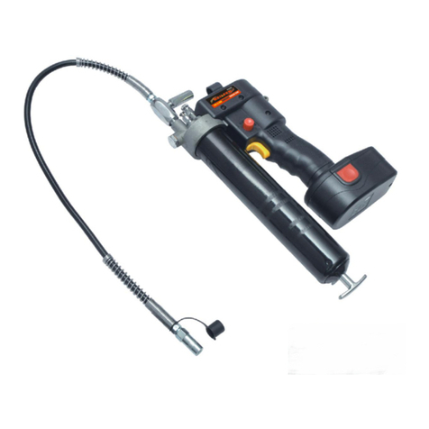
Chentronics Motivator3 User manual

Installation and Operation Manual
MNL-MOTIVATOR3REVA Page 1 of 9
REVISION DATE: 2021-DEC-15 DCO # 13824
Part Number:
07171717
KEEP THIS MANUAL IN A SAFE PLACE
FOR FUTURE REFERENCE
READ THIS MANUAL BEFORE USING THIS PRODUCT.FAILURE TO FOLLOW THE INSTRUCTIONS AND SAFETY
PRECAUTIONS IN THIS MANUAL CAN RESULT IN DAMAGE TO EQUIPMENT,SERIOUS INJURY OR DEATH.
Chentronics, LLC
50 Ohara Drive
Norwich, NY 13815, USA
TEL: +1.607.334.5531
Figure 1 – Motivator3™(Battery not shown, sold separately)
HANDHELD HIGH ENERGY IGNITION

Installation and Operation Manual
MNL-MOTIVATOR3REVA Page 2 of 9
REVISION DATE: 2021-DEC-15 DCO # 13824
www.chentronics.com
Contents
1.0 Important Safety Information........................................................................................................ 3
2.0 Definitions..................................................................................................................................... 5
3.0 Chentronics® High Energy Ignition Systems ................................................................................... 5
4.0 System Specifications .................................................................................................................... 6
4.1 Description of Equipment ................................................................................................................................. 6
4.2 Electrical Area Classification and Safety Markings............................................................................................ 6
4.3 System Electrical and Physical Specifications.................................................................................................... 6
5.0 Instructions ................................................................................................................................... 7
5.1 Three-Position Toggle Safety Switch................................................................................................................. 7
5.2 Assembly ........................................................................................................................................................... 7
5.3 System Function Test ........................................................................................................................................ 7
6.0 System Operational Inputs and Outputs........................................................................................ 8
6.1 Applying Power to Equipment .......................................................................................................................... 8
6.2 Commanding Exciter to Spark ........................................................................................................................... 8
6.3 Spark Detection Feedback ................................................................................................................................ 8
6.4 Solid Blue LED Status......................................................................................................................................... 8
7.0 Standard Components and Accessories ......................................................................................... 9
7.1 Standard System Components.......................................................................................................................... 9
7.2 Standard Accessories ........................................................................................................................................ 9
8.0 Warranty Instructions.................................................................................................................... 9
9.0 Technical Support.......................................................................................................................... 9

Installation and Operation Manual
MNL-MOTIVATOR3REVA Page 3 of 9
REVISION DATE: 2021-DEC-15 DCO # 13824
1.0 Important Safety Information
Read All Instructions before Using Equipment
The instructions provided in this manual have been prepared to serve as a general guide. It
is intended for use by qualified personnel with knowledge of equipment of this type. It is
not intended to cover all possible variations in equipment or to provide for specific
operating problems which may arise.
You are responsible for adhering to all warnings or cautions provided in this Manual.
In addition to any general safety measures provided in this Manual, you must comply with
all current national, state, local and company safety regulations at all times.

Installation and Operation Manual
MNL-MOTIVATOR3REVA Page 4 of 9
REVISION DATE: 2021-DEC-15 DCO # 13824
Safety Symbols used in this manual comply with ISO 3864.
THESE SYMBOLS ARE USED TO ALERT YOU TO POTENTIAL PERSONAL INJURY HAZARDS.
OBEY ALL SAFETY MESSAGES THAT FOLLOW THESE SYMBOLS TO AVOID POSSIBLE INJURY OR DEATH.
Indicates a hazard with a high level of risk which, if not
avoided will result in death or serious injury.
Indicates a hazard with a medium level of risk which, if not
avoided could result in death or serious injury.
Indicates a hazard with a low level of risk which, if not
avoided will result in minor or moderate injury.
HAZARDOUS VOLTAGE
The equipment contains a High Energy Ignition System which contains DANGEROUS AND
POTENTIALLY LETHAL VOLTAGE. To avoid risk of serious injury from electric shock, always
follow the safety precautions listed below:
Do not join or separate any connection to the equipment when the equipment is
energized.
Do not apply power to the equipment without an igniter attached or the igniter port
appropriately capped.
Keep the igniter firing end away from all personnel and flammable material.
The equipment must be operated by qualified personnel in accordance with applicable
local and national codes, standards, and ordinances.
The equipment is not field-repairable. Do not attempt to disassemble or repair the
equipment.

Installation and Operation Manual
MNL-MOTIVATOR3REVA Page 5 of 9
REVISION DATE: 2021-DEC-15 DCO # 13824
2.0 Definitions
Spark –An electric current arc.
High Energy Ignition – Electric spark ignition system utilizing high energy sparks for direct
ignition of hydrocarbon fuels such as gas, diesel, or #6 oil. (Note: the Motivator3™is
intended for igniting gas only)
High Energy Exciter – An electronic device that stores electric charge and releases it cyclically
in abrupt bursts to an igniter to create high power sparks.
3.0 Chentronics® High Energy Ignition Systems
Chentronics® High Energy Ignition (HEI) systems directly ignite burner fuels by providing short
time duration (impulse), high current electrical arcs commonly referred to as sparks. These
sparks are generated by abruptly releasing electrical energy (charge) stored in large capacitors.
The energy is released through an igniter driver circuit called a pulse forming network to
specialized high energy igniters. The result is a high power spark with increased ability to ignite
fuels.
Figure 2: High Energy Exciter basic schematic.
Chentronics® High Energy Ignition Systems are designed to operate in conditions of extreme
temperature, moisture, and contamination; creating high power sparks that dependably
provide direct spark ignition to a wide range of fuels in a wide range of adverse conditions.

Installation and Operation Manual
MNL-MOTIVATOR3REVA Page 6 of 9
REVISION DATE: 2021-DEC-15 DCO # 13824
4.0 System Specifications
4.1 Description of Equipment
The Chentronics® Motivator3™is a portable, battery powered High Energy Ignition System.
Figure 3: System General Arrangement
4.2 Electrical Area Classification and Safety Markings
The Motivator3™system does not have any approved certifications for use in classified areas.
4.3 System Electrical and Physical Specifications
Application: Direct Spark Ignition of Gas Fuels
Input Power: 18-20VDC Battery Pack
Exciter Type: High Energy Ignition
Exciter Duty Cycle: 30 sec ON / 60 sec OFF
Exciter Spark Command: Trigger
Exciter Spark Visual: Blue LED
Exciter Power: 1.5J per Spark at 6 Sparks per Second Nominal
Operating Temperature Limits: -25°C to +40°C
Storage Temperature Limits: -25°C to +65°C (Battery has separate temperature limits)
Humidity: 0 to 100% condensing
Enclosure: No ingress protection
Electronics Assembly Weight: Approximately 2.4lb without accessories
Typically 5-10lbs depending on battery, extension rod,
and igniter.
Dimensions: Approximately 12 x 8 x 3 inches without accessories

Installation and Operation Manual
MNL-MOTIVATOR3REVA Page 7 of 9
REVISION DATE: 2021-DEC-15 DCO # 13824
5.0 Instructions
5.1 Three-Position Toggle Safety Switch
Unused Setting Locked Setting Operation Setting
Exciter does not operate
Trigger is locked to off
Trigger operates exciter
5.2 Assembly
Confirm safety lock is in the centered position, and trigger is unable to be depressed. If using an
extension rod, install into the Motivator3™hand tight. Install Igniter Tip into Extension Rod or
Motivator3™hand tight. Confirm battery is fully charged via indicator light on the charging
station or the indicator light on the battery itself. Install Battery.
5.3 System Function Test
STARTLING NOISE
Igniters can make a loud “snapping” or “popping” noise when fired. Anticipate this noise and
warn others to expect it before operating the equipment. Alert others in area before operating
equipment.
Shift safety lock to the right, and fully depress the trigger. Sparks will flash at the igniter tip, the
indicator light on top of the exciter will flash off with each spark, and a small light will illuminate
from beneath the nose of the exciter.
The Motivator3™will continue sparking as long as the trigger is depressed. To stop sparking,
release the trigger. Note that the duty cycle of this equipment is 30 seconds on, 60 seconds off.
Operating at a rate higher than the duty cycle could damage the exciter and void the warranty.
Do not operate the Motivator3™without an igniter tip. Without an igniter tip the exciter must
absorb the energy pulse, which can damage the exciter and void the warranty.

Installation and Operation Manual
MNL-MOTIVATOR3REVA Page 8 of 9
REVISION DATE: 2021-DEC-15 DCO # 13824
6.0 System Operational Inputs and Outputs
6.1 Applying Power to Equipment
To power the Motivator3™, install a compatible battery into battery slot.
6.2 Commanding Exciter to Spark
Pressing the trigger button will command the exciter to spark the igniter. The Blue Spark LED on
top of the exciter will turn on when the exciter is attempting to fire and will briefly flash off each
time a spark output current is detected.
STARTLING NOISE
Igniters can make a loud “snapping” or “popping” noise when fired. Anticipate this noise and
warn others to expect it before operating the equipment. Alert others in area before operating
equipment.
6.3 Spark Detection Feedback
The Motivator3™system provides spark detection feedback by flashing a blue light at the top
of the exciter. Table 1 provides interpretation of light behavior.
Table 1. Spark Indicator Light Interpretation
Light Response Meaning
Consistent Flashing Blue Sparks are being generated. Exciter is functioning normally.
Erratic Flashing Blue Sparks are being generated. Igniter tip is nearing end of life, replace soon.
Solid Blue No sparks being generated. Lock Trigger, Disconnect Battery, See section 6.4.
Does not turn on Exciter not functioning. Lock Trigger, Disconnect Battery, Contact Chentronics.
6.4 Solid Blue LED Status
In the event the LED turns on solid blue when attempting to spark, verify extension rod and
igniter are installed correctly according to Section 5.0 Instructions.
If installed correctly, verify exciter is functioning correctly with a new igniter. When an igniter
has reached the end of service life, the LED indicator will respond solid blue.
If the LED continues to respond solid blue when the trigger is depressed with a new igniter, lock
trigger, disconnect battery, and contact Chentronics®.

Installation and Operation Manual
MNL-MOTIVATOR3REVA Page 9 of 9
REVISION DATE: 2021-DEC-15 DCO # 13824
7.0 Standard Components and Accessories
The following is a sample of standard parts available for use with the Motivator3™system. For
additional parts and technical drawings please contact Chentronics®.
7.1 Standard System Components
Recommended Igniter – 12000500
Recommended Extension Rod – 12000400
Test Igniter – 02000550-A1-12
7.2 Standard Accessories
North American 6.0Ah Battery –07071722
North American Battery Charger – 07071723
Test Igniter – 02000550-A1-12
Custom Fitted Carrying Case – 07071719
8.0 Warranty Instructions
For warranty related inquires please contact Chentronics® at TEL: +1.607.334.5531 or
9.0 Technical Support
For technical support related inquires beyond the scope of this Installation and Operation
This manual suits for next models
1
Table of contents
