Gedore KL-0145-120 A User manual

GEDORE Automotive GmbH
78166 Donaueschingen 78154 Donaueschingen - GERMANY Fax: +49 (0) 771 / 8 32 23-90 Internet: www.gedore-automotive.com
0145-120Ae170116.docx
KL-0145-120 A
Supporting Device
for Control Arm

2 Chapter 3
0145-120Ae170116.docx hu-gm © Copyright by GEDORE Automotive GmbH, Germany
Instruction Manual
English 3 - 7
Impressum
Im Zuge der Verbesserung und Anpassung an den Stand der Technik behalten wir uns Änderungen im Hinblick auf Aussehen, Abmessungen, Gewichte und Eigenschaften sowie
Leistungen vor.
Damit ist kein Anspruch auf Korrektur oder Nachlieferung bereits gelieferter Produkte verbunden. Streichungen können jederzeit vorgenommen werden, ohne dass ein rechtlicher
Anspruch entsteht.
Alle Hinweise zur Benutzung und Sicherheit sind unverbindlich. Sie ersetzen keinesfalls irgendwelche gesetzlichen oder berufsgenossenschaftlichen Vorschriften.
Für Druckfehler übernehmen wir keine Haftung.
Ein Nachdruck, auch auszugsweise, bedarf der vorherigen schriftlichen Zustimmung durch GEDORE Automotive GmbH.
Alle Rechte weltweit vorbehalten.
Wir verweisen auf unsere Allgemeinen Geschäftsbedingungen, ersichtlich im Impressum unter www.gedore-automotive.com.
© Copyright by GEDORE Automotive GmbH Donaueschingen (GERMANY)
Impressum/Legal Notice
As part of our commitment to continuous product improvement and adaptation to state-of-the art technology, we reserve the right to make modifications to our products with
regard to design, dimension, weight, features and performances at any time and without prior notice.
Thus, the right to adjustments or replacement deliveries of goods already delivered is excluded. Cuts and cancellations can be made by us at any time without notice and no legal
claims against us may arise or be derived from this.
All indications regarding use and safety are given for information only and without any commitment. In no case do they substitute for legal provisions or the regulations of the
Employer’s Liability Insurance Association.
Errors and omissions excepted.
Any reproduction, also in extracts, is subject to the prior written consent of GEDORE Automotive GmbH.
All rights reserved.
We refer to our General Terms and Conditions of Sale under ‘Imprint’ at www.gedore-automotive.com.
© Copyright by GEDORE Automotive GmbH Donaueschingen (GERMANY)
Impressum / Mentions légales
En raison des améliorations continues que nous apportons à nos produits et pour assurer leur adaptation constante à l'évolution des techniques, nous nous réservons le droit de
procéder à des modifications de nos produits quant à l’apparence, aux dimensions, aux poids, aux caractéristiques et aux performances à tout moment sans préavis et sans obligation
de modifier ou de remplacer des produits précédemment livrés.
Des suppressions peuvent être effectuées à tout moment et sans préavis sans qu’elles puissent donner lieu à réclamation.
Toutes les instructions d’utilisation et conseils de sécurité sont donnés sans engagement de notre part. Ils ne se substituent en aucun cas aux réglementations légales en vigueur
ou à celles émises par les associations professionnelles.
Le plus grand soin possible a été apporté à la rédaction de ce document. Toutefois, nous n’assumons aucune responsabilité pour des erreurs, omissions ou défauts d’impression
éventuels.
Une reproduction, même en partie, ne peut être effectuée qu’après autorisation écrite préalable de GEDORE Automotive GmbH.
Tous droits réservés.
Vous trouverez nos conditions générales de vente, sous Impressum/Mentions légales sur www.gedore-automotive.com.
© Copyright by GEDORE Automotive GmbH Donaueschingen (GERMANY)

3
Chapter 3 0145-120Ae170116.docx hu-gm
© Copyright by GEDORE Automotive GmbH, Germany
Instruction Manual
Table of Contents
Page
1. Essential Safety Notices .........................................................................................................4
1.1 Safety Notices and Warnings ...........................................................................................................4
1.2 Personal Protective Equipment .......................................................................................................4
1.3 Intended Use ...................................................................................................................................5
1.4 Safe and Proper Use ........................................................................................................................5
1.5 Work Environment...........................................................................................................................5
1.6 Appropriate Users ...........................................................................................................................5
2. Product Description ...............................................................................................................6
2.1 Components ....................................................................................................................................6
2.2 Technical Data ...............................................................................................................................6
3. Preparatory Work ..................................................................................................................6
3.1 Checking The Delivery. ....................................................................................................................6
3.2 Preparing the Vehicle. .....................................................................................................................6
3.3 Preparing the Tool ...........................................................................................................................6
4. Example of Use: ......................................................................................................................7
5. Accessories ............................................................................................................................7
6. Care and Storage ...................................................................................................................7
7. Maintenance and Repair by the GEDORE Automotive Service Centre.................................7
8. Environmentally Safe Disposal ..............................................................................................7

4 Chapter 3
0145-120Ae170116.docx hu-gm © Copyright by GEDORE Automotive GmbH, Germany
Instruction Manual
1.
Essential Safety Notices
Before using the supporting device for control arm, it is imperative that you read and understand the Instruction Manual. Misuse
can lead to SERIOUS INJURIES and even DEATH.
This Instruction Manual is part of the supporting device for control arm. Keep the Instruction Manual in a safe place for future reference
and pass it on to subsequent users of the supporting device for control arm. All vehicle-specific data stated herein are supplied under
reserve and without commitment.
1.1 Safety Notices and Warnings
For better differentiation, the warning notices in this Instruction Manual are classified as follows:
Warning
sign Sign reads Signification
DANGER
Indicates a hazardous situation which, if not avoided, may result in serious or fatal injuries.
CAUTION
Indicates a hazardous situation which, if not avoided, may result in moderate or minor injuries.
ATTENTION
Indicates a situation which, if not avoided, may result in possible damage to the supporting device
for control arm or its functioning, or to objects in its vicinity.
DANGER
When raising axle components, high forces come into play. As a result, there is a risk of the supporting device for control arm breaking and
falling to pieces. This will lead to parts becoming projectiles.
ALWAYS observe and do not exceed the maximum load capacity of the supporting device for control arm!
ONLY use the original spare parts from GEDORE Automotive.
NEVER use the supporting device for control arm for raising a vehicle!
ALWAYS check the supporting device for control arm prior to EACH use to ensure that it is in good order and condition.
ALWAYS ensure that the supporting device for control arm is protected from damage due to external force such as hammer blows.
ALWAYS ensure that the supporting device for control arm is secured to the wheel hub with 2x wheel bolts or lug nuts as appropriate.
NEVER exceed the maximum load capacity of the transmission jack. ALWAYS consult and adhere to the safety regulations and
specifications of the respective transmission jack!
NEVER raise/lower a vehicle by means of a car lift when working with the supporting device for control arm.
The supporting device for control arm must only be used in conjunction with a transmission jack that has been approved in
accordance with the Machinery Directive 2006/42/EC.
CAUTION
The supporting device for control arm and axle parts can cause injuries if dropped.
Always make sure that the supporting device for control arm is properly seated on the plunger of the transmission jack and secured
with the locking screw.
Always wear safety shoes/boots.
ATTENTION
Risk of damage to vehicle and supporting device for control arm.
Any work on vehicles should only be performed by qualified specialist personnel observing and complying with the directions,
provisions, and safety regulations specified by the vehicle manufacturer.
Always refer to the vehicle manufacturer’s data and instructions as only these apply to all work that is carried out on the vehicle.
1.2 Personal Protective Equipment
ALWAYS wear personal protective equipment when using the supporting device for control arm. The supporting device for control arm
can cause mechanical hazards leading to injuries such as contusions, cuts or concussions.
SAFETY GLOVES must be worn when using the supporting device for control arm.
Working with the supporting device for control arm can cause skin abrasions and contusions.
SAFETY SHOES/BOOTS with slip resistant soles and steel-toe caps (see OSHA 29 CFR 1910.136 and ANSI 241) must
be worn when using the supporting device for control arm.
Falling parts can cause serious injuries to feet and toes.

5
Chapter 3 0145-120Ae170116.docx hu-gm
© Copyright by GEDORE Automotive GmbH, Germany
Instruction Manual
1.3 Intended Use
The KL-0145-120 Asupporting device for control arm is only designed to be used in conjunction with a transmission jack for
supporting and securing control arms.
The supporting device for control arm may only be used in the manner as described in this Instruction Manual.
Any use other than for the intended purpose can result in severe injuries or even death.
1.4 Safe and Proper Use
Take the following safety precautions to prevent injuries and damage that could be caused by improper handling or unsafe use of the
supporting device for control arm.
Misuse can result in extremely severe injuries or even death.
NEVER overload the supporting device for control arm.
ALWAYS check the supporting device for control arm prior to EACH use in order to ensure that it is in good order and condition.
ALWAYS replace all damaged and worn parts prior to using the supporting device for control arm.
ONLY use the original spare parts and accessories from GEDORE Automotive on the supporting device for control arm.
1.5 Work Environment
For safety reasons, work with the supporting device for control arm should only be carried out in a safe and secure work environment.
The workplace should always be clean and tidy.
The workplace should be sufficiently large and must be secured.
1.6 Appropriate Users
This Instruction Manual is designed for technicians/mechanics in workshops.
DO NOT allow children to use the supporting device for control arm.
Purchasers/employers purchasing the supporting device for control arm MUST ensure that any person using the supporting device for
control arm has read and understood this Instruction Manual prior to using the tool. This Instruction Manual MUST be made available
to the users of the supporting device for control arm for reference at all times.

6 Chapter 3
0145-120Ae170116.docx hu-gm © Copyright by GEDORE Automotive GmbH, Germany
Instruction Manual
2.
Product Description
KL-0145-120 A - Supporting Device for Control Arm
Universal application, e.g. for the removal/installation of
suspension struts.
The device is used in conjunction with a transmission jack for
supporting and securing control arms. The support takes place via
the wheel hub.
Thanks to its special design, the device can be fixed at camber
angle position, thus, ensuring the correct raising and lowering
of control arms/axles to specified positions. This tool will greatly
simplify the removal/installation of suspension struts.
2.1
Components:
Pos. Part No. Description Qty
- KL-0145-120 A Supporting Device for Control Arm 1
composed of:
1 KL-0145-1201 Fork for Wheel Hub 1
2 KL-0145-1203 A Clamp Screw 1
3 KL-0043-5914 Locking Screw 1
4 KL-0145-1202 A Sleeve 1
2.2
Technical Data
Retaining Ø: ...................................................................... 30mm
Overall height: ................................................................ 205mm
Inclination angle:............................................................... +/- 45°
Max. load capacity: ............................................................ 300kg
3.
Preparatory Work
Before the first commissioning of the supporting device for control
arm, check and confirm you have all the parts listed in the scope of
delivery. Then, read and follow the mounting instructions.
3.1 Checking The Delivery.
3.2 Preparing the Vehicle.
Loosen and/or remove all parts necessary to enable the
support and fixing of the control arm (such as wheel etc.)
according to the manufacturer’s instructions.
3.3 Preparing the Tool.
DANGER
When raising axle components, high forces come into play. As a
result, there is a risk of the supporting device for control arm
breaking and falling to pieces. This will lead to parts becoming
projectiles.
The supporting device for control arm must only be used in
conjunction with a transmission jack that has been approved
in accordance with the Machinery Directive 2006/42/EC.
CAUTION
The supporting device for control arm and axle parts can
cause injuries if dropped.
Always make sure that the supporting device for control arm
is properly seated on the plunger of the transmission jack
and secured with the locking screw.
Always wear safety shoes/boots.
Mount supporting device for control arm to an appropriate
transmission jack (with plunger Ø of 30mm) as shown in Fig. 1.
Note: Tighten locking screw “3“ to 10 Nm.
KL-0145-120 A
EC Declaration of Conformity
EC Declaration of Conformity according to EC Directive
2006/42/EC on machinery of 17 May 2006 , (Annex II A):
Herewith we declare that the machinery described below
Supporting Device for Control Arm KL-0145-120
in its design and construction as well as in the version in which it was
placed by us on the market complies with the Essential Health and
Safety Requirements of the EC Machinery Directive 2006/42/EC.
Any modifications made to the Supporting Device for Control Arm
without our approval will invalidate this declaration.
Harmonised Standards used, in particular: DIN EN 12100 Safety of
machinery - basic concepts, general principles for design, basic
terminology, methodology, risk assessment.
Address:
GEDORE Automotive GmbH
Breslauer Str. 41
DE-78166 Donaueschingen, Germany
Donaueschingen, 23 January 2017
Dipl.-Ing Thomas Sjösten, Managing Director, GEDORE Automotive Gmb
Fig. 1: Preparing the Supporting Device for Control Arm
1
2
3
4
Ø 30mm
Transmission jack
10Nm
3

7
Chapter 3 0145-120Ae170116.docx hu-gm
© Copyright by GEDORE Automotive GmbH, Germany
Instruction Manual
4. Example of Use:
The following instructions describe how to support and secure a control arm at
the front axle with the aid of the supporting device for control arm in
conjunction with an appropriate transmission jack.
1.
DANGER
When raising axle components, high forces come into play. As a result,
there is a risk of the supporting device for control arm breaking and falling
to pieces. This will lead to parts becoming projectiles.
ALWAYS ensure that the supporting device for control arm is secured to
the wheel hub with either 2x wheel bolts or lug nuts as appropriate.
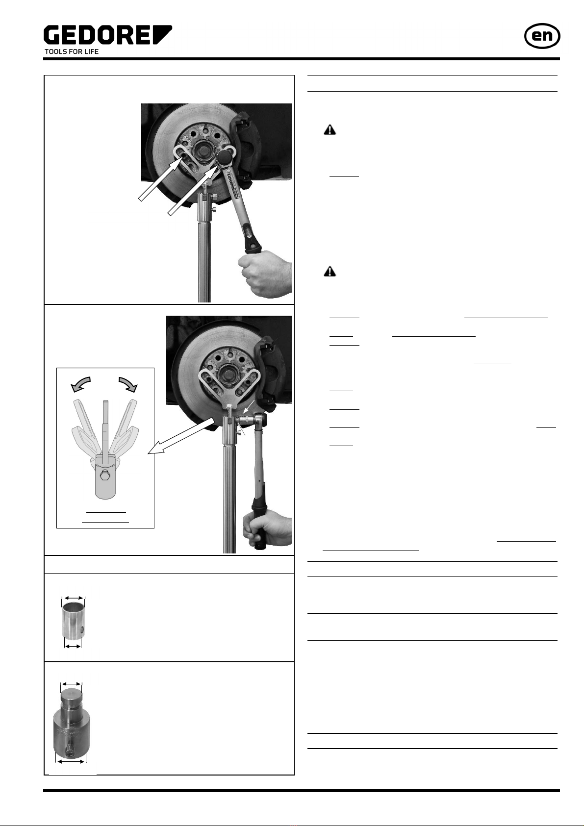
Bolt supporting device for control arm and wheel hub together using
2x wheel bolts or lug nuts as shown in Fig.
2.
Note: Tighten wheel bolts or lug nuts to 10Nm.
2. Fix supporting device for control arm at camber angle position.
To do this, tighten clamp screw “2“ as shown in Fig.
3.
Notes: Tighten clamp screw “2“ to 25 Nm.
3. DANGER
When raising axle components, high forces come into play. As a result,
there is a risk of the supporting device for control arm breaking and falling
to pieces. This will lead to parts becoming projectiles.
ALWAYS observe and do not exceed the maximum load capacity of
the supporting device for control arm!
NEVER exceed the maximum load capacity of the transmission jack.
ALWAYS consult and adhere to the safety regulations and
specifications of the respective transmission jack!
The supporting device for control arm must only be used in
conjunction with a transmission jack that has been approved in
accordance with the Machinery Directive 2006/42/EC.
NEVER raise/lower a vehicle by means of a car lift when working with
the supporting device for control arm.
ALWAYS ensure that the supporting device for control arm is
protected from damage due to external force such as hammer blows.
ALWAYS check the supporting device for control arm prior to EACH
use to ensure that it is in good order and condition.
NEVER use the supporting device for control arm for raising vehicles!
ONLY use the original spare parts from GEDORE Automotive.
ATTENTION
Risk of damage to vehicle and supporting device for control arm.
Any work on vehicles should only be performed by qualified specialist
personnel observing and complying with the directions, provisions, and
safety regulations specified by the vehicle manufacturer.
Always refer to the vehicle manufacturer’s data and instructions as only
these apply to all work that is carried out on the vehicle.
Carry out repair/maintenance work on the vehicle according to the
manufacturer’s instructions.
6. Care and Storage
ATTENTION Always clean all parts after their use with a clean cloth only. In
order to protect against corrosion, lightly lubricate all metal parts after their use
with oil and store them in a clean and dry place.
7. Maintenance and Repair by
the GEDORE Automotive Service Centre.
For safety reasons, as soon as damage is noticed on the supporting device
for control arm, immediate steps must be taken to prevent it from being
used. For professional inspection and repair of the supporting device for
control arm, please contact the GEDORE Automotive Service Centre.
Address: GEDORE Automotive GmbH
Breslauerstraße 41 // 78166 Donaueschingen
Phone: 0771 83 22 371 / Email: info@gedore-automotive.com
For additional information concerning the use of our supporting device for
control arm, please contact the GEDORE Automotive Service Centre.
8. Environmentally Safe Disposal
Recycle/dispose of the supporting device for control arm and its packaging
material in compliance with the legal rules and regulations in force.
Fig. 2: Bolt supporting device for control arm
and wheel hub together.
Fig. 3: Fix supporting device at camber angle position.
5. Accessories:
KL-0040-2571 Adaptor Sleeve, Ø 25mm
KL-0040-2588 - Adaptor Sleeve, VW, Ø 36 mm
Ø 30mm
Ø 25mm
Adjustable
camber angle
Ø 36mm
Ø 30mm
This adaptor is needed to use the KL-0145-120A
supporting device for control arm in conjunction with a
transmission jack having a plunger with Ø of 25mm.
This adaptor is needed to use the retaining device
KL-0040-258 or the supporting device KL-0145-120 A
in conjunction with the VW Transmission Jack.
Tighten wheel bolts
or lug nuts to 10Nm.
+/- 45°
2
25 Nm

GEDORE Automotive GmbH
Breslauer Strasse 41
78166 Donaueschingen
Postfach 1329
78154 Donaueschingen - GERMANY
Tel.: +49 (0) 771 / 8 32 23-0
Fax: +49 (0) 771 / 8 32 23-90
Internet: www.gedore-automotive.com
Table of contents
Other Gedore Tools manuals