Rexnord Omega Service manual

Installation Instructions •Rexnord®Omega®Metric Couplings
(Page 1 of 4) Type E and ES • Sizes 2M-140M
Rexnord 80152M
5555 S. Moorland Rd., New Berlin, WI 53151-7953 June 2016
Telephone: 262-796-4060 Fax: 262-796-4064 www.rexnord.com Supersedes 428-313M
1. General Information
1.1. Omega Couplings are designed to provide a mechanical connection between the rotating shafts of mechanical equipment, using
a torsionally soft flexible element to accommodate inherent misalignment while transmitting the power and torque between the
shafts.
1.2. These instructions are intended to help you install and maintain your Omega coupling. Please read these instructions prior to
installing the coupling, and prior to maintenance of the coupling and connected equipment. Keep these instructions near the
coupling installation and available for review by maintenance personnel.
1.3. Rexnord Industries, LLC owns the copyright of this material. These Installation and Maintenance instructions may not be
reproduced in whole or in part for competitive purposes.
1.4. Symbol descriptions:
Danger of injury to persons.
Damages on the machine possible.
Pointing to important items.
2. Safety and Advice Hints
DANGER!
2.1. Safety should be a primary concern in all aspects of coupling installation, operation and maintenance.
2.2. All rotating power transmission products are potentially dangerous and can cause serious injury. They must be guarded in
compliance with OSHA, ANSI, ATEX and any other local standard for the applications they are used. It is the responsibility of the
user to provide proper guarding.
2.3. Failure to secure cap screws properly could cause coupling component(s) to dislodge during operation and result in personal
injury. See Table 3 for proper tightening torques.
2.4. Do not use on turbine drives if the coupling cannot be protected from steam leakage or overspeed situations beyond the
coupling’s published speed rating.
2.5. Before installing this coupling on systems involving sleeve bearings, herringbone gearsets or other axially sensitive devices,
consult Rexnord.
2.6. Elastomeric couplings can hold a static electric charge that may discharge and ignite in an explosive environment. Both shafts of
the connected equipment must have a path to ground.
3. Preventative Maintenance
DANGER!
Do not make contact with the coupling when it is rotating and/or in operation.
3.1. Periodic visual inspection is necessary to evaluate the condition of the flex element. Inspection can be done during the operation
using a strobe light.
3.2. When inspecting the element look for:
• Fatigue cracks at element splits, discoloration and surface cracking in body of element.
ATTENTION! Replace element if necessary.
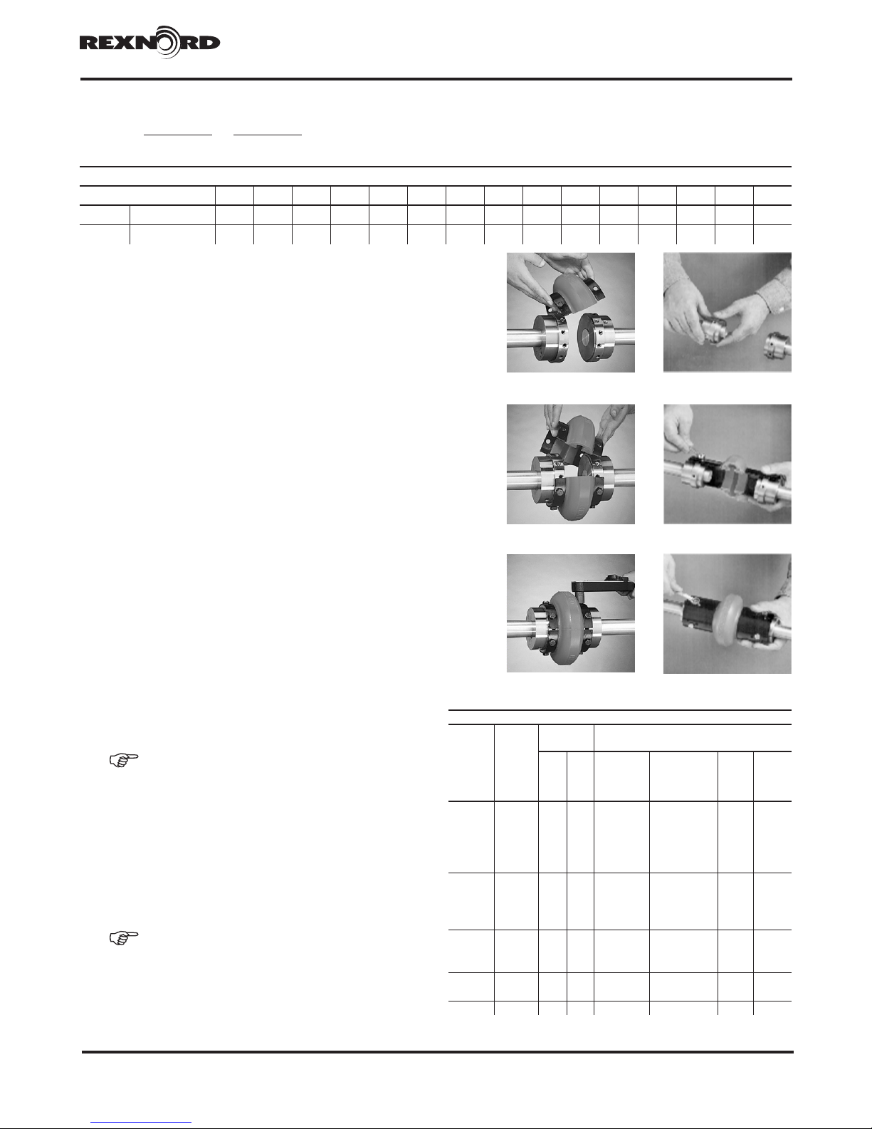
4. Element Replacement
DANGER!
Stop the motor and lock it out to prevent start-up during installation of coupling.
4.1. Always replace both half elements.
4.2. Install both half elements from the same box.
4.3. Follow installation instructions (see Section 7, Rexnord Omega Coupling Installation).
4.4. Tighten element cap screws to proper torque (see Table 3).
The designation ATEX (Atmosphere Explosibles) has established itself for the new guidelines. ATEX 100a controls all
regulations for the condition of explosion-proof equipment.
Model No. ___________________ Category____________________ Reference ___________________
Mfg Year ____________________ Max Temperature _____________

Installation Instructions •Rexnord®Omega®Metric Couplings
(Page 2 of 4) Type E and ES • Sizes 2M-140M
80152M Rexnord
June 2016 5555 S. Moorland Rd., New Berlin, WI 53151-7953
Supersedes 428-313M Telephone: 262-796-4060 Fax: 262-796-4064 www.rexnord.com
5. Rexnord Omega Coupling Design and Part Numbers
Type E Type ES
Table 1 - Omega part numbers
Size
Elastomer Element Hubs Element
cap screws
METRIC
High speed
rings
Sleeve
extension
E
ES
Rough bore
BSW UNF QD hub
Taper Bush
hub
Taper Bush
hub
2M 7300005M 7300075M 7300215M - - - 7301410 -
3M 7300010M 7300080M 7300240M 7300795M 7300730M - 7301420 7369574M
4M 7300015M 7300085M 7300270M 7300800M 7300740M 7300860M 7301420 7369575M
5M 7300020M 7300090M 7300305M 7300805M 7300745M 7300865M 7301420 7369576M
10M 7300025M 7300095M 7300340M 7300810M 7300750M 7300870M 7301450 7369577M
20M 7300030M 7300100M 7300650M 7300815M 7300755M 7300875M 7393101 7301100M 7369578M
30M 7300035M 7300105M 7300660M 7300820M 7300760M 7300880M 7393101 7301105M 7369579M
40M 7300040M 7300110M 7300670M 7300825M 7300765M 7300885M 7393105 7301110M 7369580M
50M 7300045M 7300115M 7300680M 7300830M 7300770M 7300890M 7393105 7301115M 7369581M
60M 7300050M 7300120M 7300690M 7300835M 7300775M 7300895M 7393109 7301120M 7369582M
70M 7300055M 7300125M 7300700M 7300840M 7300780M 7300900M 7393109 7301125M 7369583M
80M 7300060M 7300130M 7300710M 7300845M 7300785M 7300905M 7393109 7301130M 7369584M
100M 7300065M - 7300720M 7300850M 7300850M - 7301530 - 7369834M
120M 7300070M - 7300725M 7300855M 7300855M - 7301540 - 7369835M
140M 7300071M - 7300727M 7300858M 7300857M - 7301545 - -
6. Drive Alignment
DANGER!
Stop the motor and lock it out to prevent start-up during installation of coupling.
STEP 1
B
A
360º
b (max)__________ mm
a (min)___________ mm
∆Ka = (b-a)
∆Ka = _____________
STEP 2
∆Kr __________ mm
360
r
ATTENTION! Improper alignment of the equipment or hubs may result in hub contact and sparking.

Installation Instructions •Rexnord®Omega®Metric Couplings
(Page 3 of 4) Type E and ES • Sizes 2M-140M
Rexnord 80152M
5555 S. Moorland Rd., New Berlin, WI 53151-7953 June 2016
Telephone: 262-796-4060 Fax: 262-796-4064 www.rexnord.com Supersedes 428-313M
STEP 3
∆Ka +∆Kr ≤ 1
∆Ka max ∆Kr max
Table 2 - Maximum Misalignment – mm
Coupling Size 2M 3M 4M 5M 10M 20M 30M 40M 50M 60M 70M 80M 100M 120M 140M
Angular ∆ Ka max 3 4 5 6 7 6 7 9 11 8 8 10 9 12 14
Radial ∆ Kr max 2 2 2 2 2 2 2 2 2 3 3 3 5 5 5
7. Rexnord Omega Coupling Installation
STEP 1
7.1. Clean dirt and burrs from shafts and hub bores.
7.2. Be sure the keys fit shafts properly.
7.3. Position both hubs on the shaft without tightening the
setscrews.
7.4. Use a half element to set proper hub spacing.
7.5. When the hubs are properly spaced, tighten
the setscrews.
7.6. When using tapered bushings, follow bushing
manufacturer’s instructions.
STEP 2
7.7. Mount first half element to the hubs using cap screws
provided.
7.8. Rotate the shaft 180 degrees and secure second half
element.
7.9. If shaft cannot be rotated, mount half elements at 90
degrees.
STEP 3
7.10. Tighten all cap screws to the torques specified in Table
3.
7.11. Align equipment.
7.12. Install proper guarding prior to equipment start-up.
ATTENTION! When installing the element, first seat all
the cap screws with a light torque, then tighten all cap
screws to proper torque using a torque wrench.
8. Cap Screw Torque
8.1. Do not lubricate cap screw threads.
8.2. Cap screws must have a thread-locking adhesive
applied.
8.3. Tighten cap screws by using torque wrench.
ATTENTION! Do not lubricate cap screw threads.
∆Ka – refer to Step 1
∆Kr – refer to Step 2
∆Ka max & ∆Kr max – refer to Table 2
Type E Type ES
Type E Type ES
Type E Type ES
Table 3 - Cap Screw Torque
Coupling
size Quantity
Torque -
DRY Metric
In.
Lbs Nm
Part
number
Steel
Part number
Stainless steel
Thread
size
Wrench
size
2M 8+8
204 23
7301410 7301410SSM
M6 10
3M 8+8 7301420 7301427
4M 8+8 7301420 7301427
5M 8+8 7301420 7301427
10M 12+12 7301450 7301457
20M 12
468 53
7393101 7393102
M10 13
30M 12 7393101 7393102
40M 16 7393105 7393106
50M 16 7393105 7393106
60M 16
816 92
7393109 7393110
M12 1570M 16 7393109 7393110
80M 16 7393109 7393110
100M 20 3240 370 7301530 7301537 M20 30
120M 24 7301540 7301547
140M 32 7080 800 7301545 7301557 M24 36

Installation Instructions •Rexnord®Omega®Metric Couplings
(Page 4 of 4) Type E and ES • Sizes 2M-140M
80152M Rexnord
June 2016 5555 S. Moorland Rd., New Berlin, WI 53151-7953
Supersedes 428-313M Telephone: 262-796-4060 Fax: 262-796-4064 www.rexnord.com
9. Rexnord Omega Hub Mounting Options
9.1. Hubs can be installed:
• flush with the shaft end (D)
• extended beyond the end of the shaft (E)
• recessed behind the shaft end (F)
ATTENTION! Shaft engagement length should be >0.8
times shaft diameter, bushed hubs must engage 100%.
D E F
10. Rexnord Omega “Type E” Mounting Options
(IN) (IN)
C
(IN)
C
(OUT)
C
(OUT)
(OUT)
Arrangement
A
Arrangement
B
Arrangement
C
Table 4 - Type E Mounting Options
2M 3M 4M 5M 10M 20M 30M 40M 50M 60M 70M 80M 100M 120M 140M
A 36 8 8 8 8 13 12 8 11 8 18 17 44 57 76
B 41 27 27 34 34 39 41 42 51 53 64 83 70 91 102
C 46 46 46 59 59 65 69 75 91 97 109 149 95 124 127
11. Rexnord Omega “Type ES” Mounting Options
Table 5 - Spacer coupling (ES) Hub mounting options for industry shaft gaps
Coupling
size
ISO (mm) ANSI (in)
100 140 180 250 3 3.5 4 5 7 8 9.5 10
ES 2-RM A-A A*-A*
ES 3-RM C-C A-A B*-B* A-B
ES 4-RM C-C A-A B*-B* B*-B* A-B
ES 5-RM C-C A-A A*-A* A*-A* A-B
ES 10-RM C-C B-B A*-A* A-B
ES 20M A*-B* B-B A-A A*-C* C-C A-A
ES 30M B-C* B-B A-A A*-B* C-C A-A
ES 40M B-B* B-B A-A C-C A-A
ES 50M A-C* B-B A-A C-C A-A
ES 60M A-A* B-B A-A B-B* B-B A-A
ES 70M B-B A-A B-B A-A
ES 80M B-B A-A B-B A-A
* Hub mounted inboard
Both hubs mounted
outboard
Shaft
Gap
Shaft
Gap
Shaft
Gap
C
A
B
CA
B
One hub mounted outboard
One hub mounted inboard
Shaft
Gap
Shaft
Gap
Shaft
Gap
Both hubs mounted
inboard
Shaft
Gap
Shaft
Gap
Shaft
Gap
Table of contents