NOTICE!
Loss of function and damage to property.
• Use suitable cables.
– Dimension conductor cross-section adequately.
– Use screened cables.
1. Connect cable to the servo drive èObserve documentation for cable and
servo drive.
2. Connect cable to the motor.
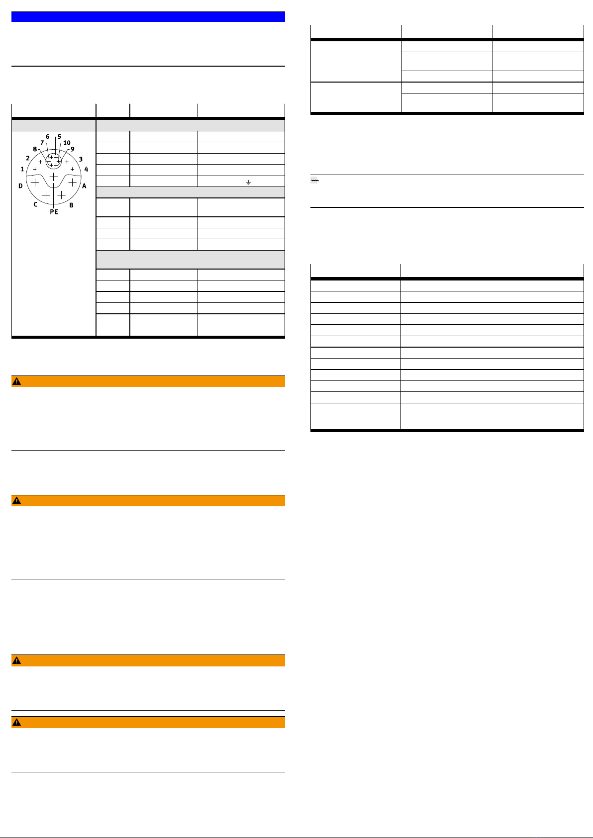
Plug M23, 15-pin Pin Designation Function
Servo motor EMMT-AS-...
A U Motor phase U
B V Motor phase V
C W Motor phase W
D – Not present
PE PE Protective earth
Holding brake EMMT-AS-...-...B
1 BR– Holding brake, reference
potential 0V
2 – Not present
3 – Not present
4 BR+ Holding brake, 24VDC
Absolute encoder EnDat 2.2, single-turn/multi-turn EMMT-
AS-...-...S/M
5 USSupply voltage
6 GND Earth
7 DATA+ Positive data signal (RS485)
8 DATA– Negative data signal (RS485)
9 CLOCK+ Positive clock signal
10 CLOCK– Negative clock signal
Tab. 3 Plug for motor/absolute encoder EnDat2.2/holding brake
9 Commissioning
WARNING!
Risk of injury due to unexpected movement of components.
• When releasing the holding brake, secure the driven mechanical system to
prevent unintended movement.
• Deenergise the motor before releasing the holding brake manually.
• Before setting the enable signal, protect the traversing range of the driven
mechanical system from access.
– Commission the motor together with the servo drive èDocumentation for
servo drive.
10 Operation
WARNING!
Risk of injury from touching hot surfaces.
Contact with housing can cause burn injuries. This can frighten people and cause
them to act in an unpredictable manner. This can lead to other forms of secondary
damage.
• Avoid unconscious touching of the housing.
• Inform operating and maintenance staff about the possible hazards.
• Before maintenance work: Let the drive cool down to below 40°C.
11 Maintenance
11.1 Cleaning
Before cleaning, the product must be cooled down to below 40°C.
Clean the outside of the product with a soft cloth as required. Cleaning agents
include all non-abrasive media.
11.2 Disassembly
WARNING!
Risk of injury due to electric shock.
• Switch off power supply prior to assembly and installation work; ensure that
it is off and secure it against being switched back on.
Cancelling the enable signal is not sufficient.
WARNING!
Risk of injury due to unexpected movement of components.
• Bring moving parts of the connected mechanical system into a secure posi-
tion (e.g. for vertical installation, move the slide into the lower end position).
• Only then should you disconnect the motor from the mechanical system.
11.3 Fault clearance
Fault description Cause Remedy
Excessive load Reduce load.
Servo drive has not yet been
enabled.
Check signals.
Motor shaft does not turn.
Holding brake is active. Release holding brake.
Cabling error Check and correct cabling.Motor turns in the wrong direc-
tion or vibrates. Controller parameter is incor-
rect.
Check and correct controller
parameter.
Tab. 4
11.4 Repair
Send the product to the Festo repair service for repair.
12 Disposal
ENVIRONMENT!
Send the packaging and product for environmentally sound recycling in accord-
ance with the current regulations èwww.festo.com/sp.
13 Technical data
Technical data for the product:
1. Internet èwww.festo.com/pk.
2. Product labelling 2 with the following values:
Designation1) Description
M0[Nm] Stall torque
MN[Nm] Nominal torque
I0[A] Continuous stall current
INph [A] Nominal current
nN[rpm] Nominal speed
nmax [rpm] Maximum speed
UZK [V] Nominal operating voltage DC
UB[V] Operating voltage DC, holding brake
ke [mVmin] Voltage constant
IPxx Degree of protection
Class 155 (F) Temperature class F (155°C)
CE marking (see
declaration of con-
formity)2)
To EU EMC Directive
1) All data as per IEC60034
2) Maximum length of individual connecting cables: 30m
Tab. 5 Designations on the product labelling


