WK2 OFF-ROAD FRONT BUMPER
INSTALL INSTRUCTIONS
REVISION B
29 AUGUST 2022
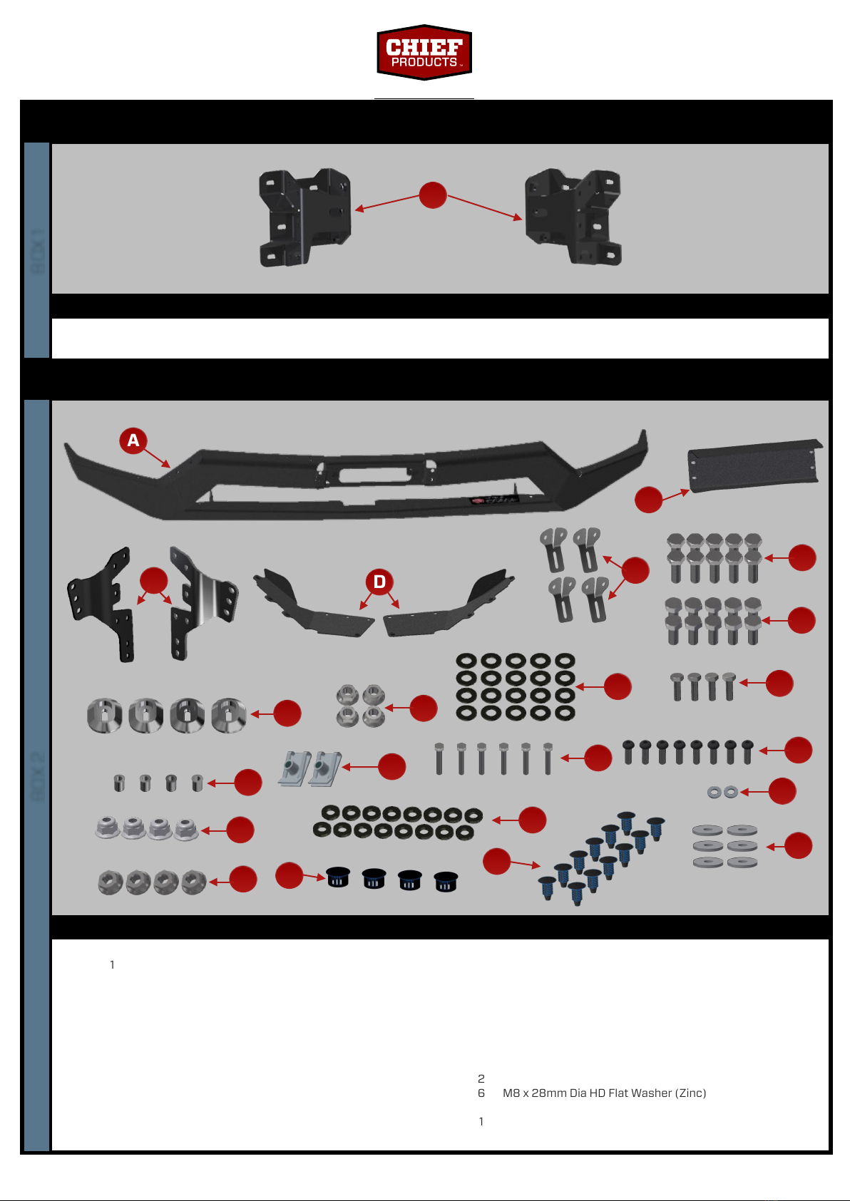
WK2 OFF-ROAD FRONT BUMPER (ACC KIT)
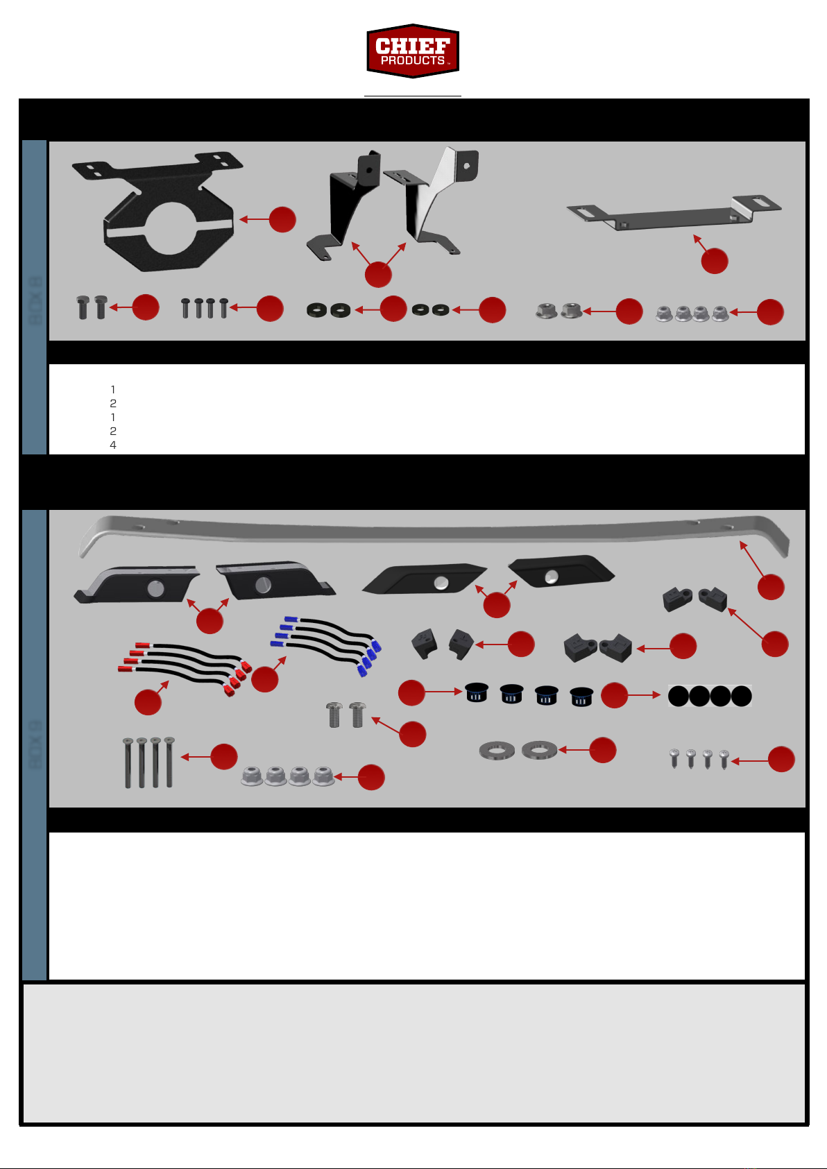
WK2 Off-Road Front Bumper (Advanced Parking Sensor Kit)
Sensor Housing Top Bar (Gloss Black or Billet Silver)
Sensor Housing Inner (Left + Right)
Sensor Retainer Inner (Left + Right)
Sensor Housing Outer (Left + Right)
Sensor Retainer Outer Large (Left + Right)
Sensor Retainer Outer Small (Left + Right)
Sensor Harness Extensions (VATT-21-010)
Sensor Harness Extensions (VATT-21-011)
Blanking Plug 20mm Dia Head
Sensor Sticker Sheet
M6 x 60mm Countersunk Socket (SS316)
M6 Hex Flange Nylock CL70 Nut (SS316)
M6 x 12mm Button Head Socket (SS316)
M6 Flat Washer (SS316)
3.5mm (6G) x 13mm Screw, Self Tapping (Zinc)
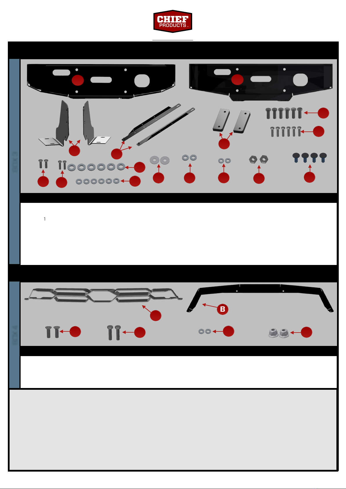
WK2 Off-Road Front Bumper (ACC Kit)
ACC Guard (Textured Black)
ACC Mount Brackets Non-Winch (Left + Right)
ACC Mount Bracket Winch
M10 x 25mm Hex Head 10.9 Bolt (Zinc)
M6 x 20 Socket Button Head CL50 Bolt (SS316, Black)
M10 Wedge-Lock Extended Washer (SS316, Black)
M6 Wedge-Lock Extended Washer (SS316, Black)
M10 CL10 Hex Flange Nut
M6 Hex Flange Nylock CL70 Nut (SS316)
WK2 OFF-ROAD FRONT BUMPER (ADVANCED PARKING SENSOR KIT) [All
Variants]