manuals.online logo
Brands
  1. Home
  2. •
  3. Brands
  4. •
  5. Lennox
  6. •
  7. Heat Pump
  8. •
  9. Lennox 14HPX Installation and operation manual

Lennox 14HPX Installation and operation manual

Other manuals for 14HPX

3

This manual suits for next models

7

Other Lennox Heat Pump manuals

Lennox 4HP14 User manual

Lennox

Lennox 4HP14 User manual

Lennox 12HPB Series User manual

Lennox

Lennox 12HPB Series User manual

Lennox Elite XP20-024-230 User manual

Lennox

Lennox Elite XP20-024-230 User manual

Lennox HPXA12 SERIES User manual

Lennox

Lennox HPXA12 SERIES User manual

Lennox 14HPX User manual

Lennox

Lennox 14HPX User manual

Lennox Elite XP13-030-230 User manual

Lennox

Lennox Elite XP13-030-230 User manual

Lennox SW 036 User manual

Lennox

Lennox SW 036 User manual

Lennox T?CLASS TPA S4 User manual

Lennox

Lennox T?CLASS TPA S4 User manual

Lennox HP16-211V User manual

Lennox

Lennox HP16-211V User manual

Lennox XP15 User manual

Lennox

Lennox XP15 User manual

Lennox KGB Series Installation and operation manual

Lennox

Lennox KGB Series Installation and operation manual

Lennox CSC User manual

Lennox

Lennox CSC User manual

Lennox Elite XP16024 User manual

Lennox

Lennox Elite XP16024 User manual

Lennox TPA036S2 User manual

Lennox

Lennox TPA036S2 User manual

Lennox XP14 User manual

Lennox

Lennox XP14 User manual

Lennox HS20-211 Setup guide

Lennox

Lennox HS20-211 Setup guide

Lennox Elite 13 User manual

Lennox

Lennox Elite 13 User manual

Lennox XP13 User manual

Lennox

Lennox XP13 User manual

Lennox Value 10ACB Series User manual

Lennox

Lennox Value 10ACB Series User manual

Lennox LRP14G User manual

Lennox

Lennox LRP14G User manual

Lennox HP22-261 User manual

Lennox

Lennox HP22-261 User manual

Lennox CHP29 Series User manual

Lennox

Lennox CHP29 Series User manual

Lennox Elite XP14-018-230 User manual

Lennox

Lennox Elite XP14-018-230 User manual

Lennox LCH Series Installation and operation manual

Lennox

Lennox LCH Series Installation and operation manual

Popular Heat Pump manuals by other brands

Daikin RXL12QMVJU Service manual

Daikin

Daikin RXL12QMVJU Service manual

AIREDALE BluCube CUR092V16-1CO-0 Installation and maintenance manual

AIREDALE

AIREDALE BluCube CUR092V16-1CO-0 Installation and maintenance manual

Calyenty RBH 125 Customer's manual

Calyenty

Calyenty RBH 125 Customer's manual

GRE HPGI50 owner's manual

GRE

GRE HPGI50 owner's manual

Carrier 30XW Installation, operation and maintenance instructions

Carrier

Carrier 30XW Installation, operation and maintenance instructions

Hayward SUMHEAT HP5131DT3 Installation instructions manual

Hayward

Hayward SUMHEAT HP5131DT3 Installation instructions manual

REMKO SQW 400 Electrical wiring

REMKO

REMKO SQW 400 Electrical wiring

Sanyo SAP120FCH Service manual

Sanyo

Sanyo SAP120FCH Service manual

Daikin EHYHBH05AA Operation manual

Daikin

Daikin EHYHBH05AA Operation manual

Panasonic WH-SDF03E3E5 Design handbook

Panasonic

Panasonic WH-SDF03E3E5 Design handbook

Airxcel 45000 Series Installation, operation and maintenance instructions

Airxcel

Airxcel 45000 Series Installation, operation and maintenance instructions

Mitsubishi Electric PUZ-SWM60VAA Service manual

Mitsubishi Electric

Mitsubishi Electric PUZ-SWM60VAA Service manual

Dimplex LI 16I-TUR Installation and operating instruction

Dimplex

Dimplex LI 16I-TUR Installation and operating instruction

Carrier WSHP Open v3 Integration guide

Carrier

Carrier WSHP Open v3 Integration guide

Mitsubishi Electric EHSE-YM9EC Service manual

Mitsubishi Electric

Mitsubishi Electric EHSE-YM9EC Service manual

TGM CTV14CN018A Technical manual

TGM

TGM CTV14CN018A Technical manual

Carrier 38MGQ Series installation instructions

Carrier

Carrier 38MGQ Series installation instructions

Kokido K2O K880BX/EU Owner's manual & installation guide

Kokido

Kokido K2O K880BX/EU Owner's manual & installation guide

manuals.online logo
manuals.online logoBrands
  • About & Mission
  • Contact us
  • Privacy Policy
  • Terms and Conditions

Copyright 2025 Manuals.Online. All Rights Reserved.

Page 1 ©2007 Lennox Industries Inc.
Corp. 0719−L5 14HPX
Service Literature 1.5 to 5 ton
Revised 06−2008
14HPX SERIES UNITS
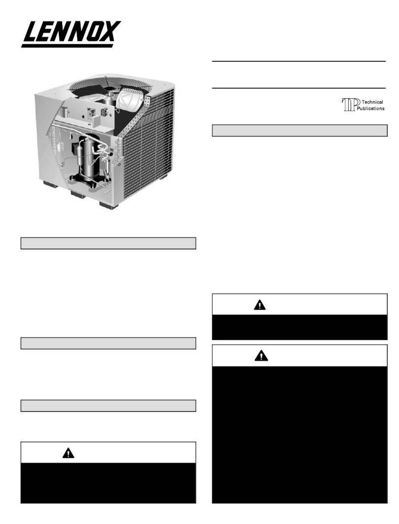
The 14HPX is a residential split-system heat pump. The
series is designed for use with expansion valves (TXV) and
HFC−410A refrigerant. All 14HPX units utilize scroll compres-
sors.
14HPX series units are available in 1−1/2, 2, 2 -1/2, 3, 3
-1/2, 4 and 5 ton capacities. All major components (indoor
blower and coil) must be matched according to Lennox rec-
ommendations for the compressor to be covered under
warranty. Refer to the Engineering Handbook for approved
system matchups.
This manual is divided into sections which discuss the
major components, refrigerant system, charging proce-
dure, maintenance and operation sequence.
Information contained in this manual is intended for use by
qualified service technicians only. All specifications are subject
to change.
ELECTROSTATIC DISCHARGE (ESD)
Precautions and Procedures
CAUTION
Electrostatic discharge can affect electronic
components. Take precautions during unit instal-
lation and service to protect the unit’s electronic
controls. Precautions will help to avoid control
exposure to electrostatic discharge by putting
the unit, the control and the technician at the
same electrostatic potential. Neutralize electro-
static charge by touching hand and all tools on an
unpainted unit surface before performing any
service procedure.
WARNING
Refrigerant can be harmful if it is inhaled. Refrigerant
must be used and recovered responsibly.
Failure to follow this warning may result in person-
al injury or death.
CAUTION
In order to avoid injury, take proper precaution when
lifting heavy objects.
Table of Contents
Specifications / Electrical Data Page 2. . . . . . . . .
I Unit Components Page 4. . . . . . . . . . . . . . . . . . .
II Refrigerant System Page 14. . . . . . . . . . . . . . . . .
III Charging Page 17. . . . . . . . . . . . . . . . . . . . . . . . .
IV Maintenance Page 22. . . . . . . . . . . . . . . . . . . . . .
V Diagrams Page 23. . . . . . . . . . . . . . . . . . . . . . . . .
Page 2
SPECIFICATIONS
General
Dt
Model No. 14HPX−018 14HPX−024 14HPX−030 614HPX−036
Data Nominal Tonnage 1.5 2 2.5 3
1Sound Rating Number 76 76 76 79
Connections
(t)
Liquid line o.d. − in. 3/8 3/8 3/8 3/8
(sweat) Vapor line o.d. − in. 3/4 3/4 3/4 7/8
2Refrigerant HFC−410A charge furnished 8 lbs. 4 oz. 8 lbs. 0 oz. 7 lbs. 2 oz. 9 lbs. 12 oz.
Outdoor
Cil
Net face area
ft
Outer coil 13.30 13.30 15.21 19.39
Coil sq. ft. Inner coil 12.60 12.60 14.50 18.77
Tube diameter − in. 5/16 5/16 5/16 5/16
No. of rows 2 2 2 2
Fins per inch 22 22 22 22
Outdoor
F
Diameter − in. 18 18 18 26
Fan No. of Blades 3 3 3 4
Motor hp 1/10 1/10 1/10 1/3
Cfm 2165 2165 2232 4090
Rpm 1015 1015 1035 844
Watts 171 171 165 299
Shipping Data − lbs. 1 package 156 156 166 212
ELECTRICAL DATA
Line voltage data − 60 hz − 1ph 208/230V 208/230V 208/230V 208/230V
3Maximum overcurrent protection (amps) 20 30 30 30
4Minimum circuit ampacity 11.9 17.5 17.0 19.4
Compressor Rated Load Amps 8.97 13.46 13.1 14.1
p
Locked Rotor Amps 48 58 64 77
Power Factor 0.96 0.97 0.98 0.98
Outdoor
FMt
Full Load Amps 0.70 0.70 0.70 1.8
Fan Motor Locked Rotor Amps 1.4 1.4 1.4 2.9
OPTIONAL ACCESSORIES − must be ordered extra
Compressor Crankcase Heater 93M04 SS S
p
Factory S
Compressor Hard Start Kit 10J42 S S S S
Compressor Low Ambient Cut−Off 45F08 S S S S
Compressor Sound Cover 69J03 S S S S
Freezestat 3/8 in. tubing 93G35 S S S S
5/8 in. tubing 50A93 S S S S
Hail Guards 92M89 S S
92M88 S
27W34 S
Indoor Blower Off Delay Relay 58M81 S S S S
Loss of Charge Kit 84M23 S S S S
5Low Ambient Kit 54M89 S S S S
Mild Weather Kit 33M07 S S S S
Monitor Kit − Service Light 76F53 S S S S
Mounting Base 69J06 SSS
g
69J07 S
Outdoor
Th t t Kit
Thermostat 56A87 S S S S
Thermostat Kit Mounting Box 31461 SS S S
Refrigerant
Line Sets
L15−41−20
L15−41−30
L15−41−40
L15−41−50
SSS
e Sets
L15−65−30 L15−65−40
L15−65−50
S
Unit Stand−Off Kit 94J45 S S S S
NOTE − Extremes of operating range are plus 10% and minus 5% of line voltage.
1Sound Rating Number rated in accordance with test conditions included in ARI Standard 270.
2Refrigerant charge sufficient for 15 ft. length of refrigerant lines.
3HACR type circuit breaker or fuse.
4Refer to National or Canadian Electrical Code manual to determine wire, fuse and disconnect size requirements.
5Crankcase Heater and Freezestat are recommended with Low Ambient Kit.
614HPX−036 not available in Canada.
Page 3
SPECIFICATIONS
General
Dt
Model No. 14HPX−042 14HPX−048 14HPX−060
Data Nominal Tonnage 3.5 4 5
1Sound Rating Number 79 80 80
Connections
(t)
Liquid line o.d. − in. 3/8 3/8 3/8
(sweat) Vapor line o.d. − in. 7/8 7/8 1-1/8
2Refrigerant HFC−410A charge furnished 12 lbs. 7 oz. 12 lbs. 10 oz. 16 lbs. 0 oz.
Outdoor
Cil
Net face area
ft
Outer coil 24.93 24.93 29.09
Coil sq. ft. Inner coil 24.13 24.13 28.16
Tube diameter − in. 5/16 5/16 5/16
No. of rows 2 2 2
Fins per inch 22 22 22
Outdoor
F
Diameter − in. 26 26 26
Fan No. of Blades 4 4 4
Motor hp 1/3 1/3 1/3
Cfm 4347 4347 4550
Rpm 843 843 830
Watts 299 299 307
Shipping Data − lbs. 1 package 257 262 307
ELECTRICAL DATA
Line voltage data − 60 hz − 1ph 208/230V 208/230V 208/230V
3Maximum overcurrent protection (amps) 40 50 60
4Minimum circuit ampacity 24.2 29 34.8
Compressor Rated Load Amps 17.94 21.79 26.41
p
Locked Rotor Amps 112 117 134
Power Factor 0.94 0.95 0.98
Outdoor
FMt
Full Load Amps 1.8 1.8 1.8
Fan Motor Locked Rotor Amps 2.9 2.9 2.9
OPTIONAL ACCESSORIES − must be ordered extra
Compressor Crankcase Heater Factory SS S
Compressor Hard Start Kit 10J42 S S
p
81J69 S
Compressor Low Ambient Cut−Off 45F08 S S S
Compressor Sound Cover 69J03 S S S
Freezestat 3/8 in. tubing 93G35 S S S
5/8 in. tubing 50A93 S S S
Hail Guards 27W36 S S
94M94 S
Indoor Blower Off Delay Relay 58M81 S S S
Loss of Charge Kit 84M23 S S S
5Low Ambient Kit 54M89 S S S
Mild Weather Kit 33M07 S S S
Monitor Kit − Service Light 76F53 S S S
Mounting Base 69J07 S S S
Outdoor
Th t t Kit
Thermostat 56A87 S S S
Thermostat Kit Mounting Box 31461 SS S
Refrigerant
Line Sets
L15−65−30 L15−65−40
L15−65−50
S S
e Sets
Field Fabricate S
Unit Stand−Off Kit 94J45 S S S
NOTE − Extremes of operating range are plus 10% and minus 5% of line voltage.
1Sound Rating Number rated in accordance with test conditions included in ARI Standard 270.
2Refrigerant charge sufficient for 15 ft. length of refrigerant lines.
3HACR type circuit breaker or fuse.
4Refer to National or Canadian Electrical Code manual to determine wire, fuse and disconnect size requirements.
5Crankcase Heater and Freezestat are recommended with Low Ambient Kit.
Page 4
I − UNIT COMPONENTS
Unit components are illustrated in figure 1.
14HPX UNIT COMPONENTS
FIGURE 1
service valves
compressor
reversing valve
condenser fan
drier
muffler
high pressure switch
(on liquid line, hidden)
txv valve
FIGURE 2
DUAL CAPACITOR
(C12)
COMPRESSOR
CONTACTOR
(K1)
14HPX UNIT CONTROL BOX
GROUNDING
LUG DEFROST
CONTROL
(CMC1)
A − Control Box (Figure 2)
14HPX units are not equipped with a 24V transformer. All
24 VAC controls are powered by the indoor unit. Refer to
wiring diagram.
Electrical openings are provided under the control box cov-
er. Field thermostat wiring is made to a 24V terminal strip
located on the defrost control board located in the control
box. See figure 3.
24V THERMOSTAT TERMINAL STRIP
FIGURE 3
W1 C L R O Y1*Y2
*not used
1 − Compressor Contactor (K1)
The compressor is energized by a contactor located in the
control box. See figure 2. Single−pole contactors are used
in 14HPX series units. See wiring diagrams for specific
unit. K1 is energized through the CMC1 board by the in-
door thermostat terminal Y1 (24V) when thermostat de-
mand is present.
DANGER
Electric Shock Hazard.
May cause injury or death.
Disconnect all remote electrical power
supplies before opening unit panel. Unit
may have multiple power supplies.
Some units are equipped with single−
pole contactors. When unit is equipped
with a single−pole contactor, line voltage
is present at all components (even when
unit is not in operation).
2 − Dual Capacitor (C12)
The compressor and fan in 14HPX series units use permanent
split capacitor motors. The capacitor is located inside the unit
control box (see figure 2). A single dual" capacitor (C12) is
used for both the fan motor and the compressor (see unit wir-
ing diagram). The fan side and the compressor side of the ca-
pacitor have different MFD ratings.
Page 5
3 − Defrost System (CMC1)
The demand defrost control measures differential tem-
peratures to detect when the system is performing poorly
because of ice build−up on the outdoor coil. The controller
self−calibrates" when the defrost system starts and after
each system defrost cycle. The defrost control board com-
ponents are shown in figure 4.
The control monitors ambient temperature, outdoor coil
temperature, and total run time to determine when a de-
frost cycle is required. The coil temperature probe is de-
signed with a spring clip to allow mounting to the outside
coil tubing. The location of the coil sensor is important for
proper defrost operation.
NOTE − The demand defrost board accurately measures
the performance of the system as frost accumulates on the
outdoor coil. This typically will translate into longer running
time between defrost cycles as more frost accumulates on
the outdoor coil before the board initiates defrost cycles.
Diagnostic LEDs
The state (Off, On, Flashing) of two LEDs on the defrost
board (DS1 [Red] and DS2 [Green]) indicate diagnostics
conditions that are described in table 2.
24V TERMINAL
STRIP
CONNECTIONS
DIAGNOSTIC
LEDS
PRESSURE
SWITCH CIRCUIT
CONNECTIONS
TEST PINS
NOTE − Component Locations Vary by Board Manufacturer.
Y2 not used on 14HPX
SENSOR
PLUG IN
(COIL & AM-
BIENT
SENSORS)
REVERSING
VALVE
DELAY
PINS
LOW
AMBIENT
THERMOSTAT
PINS
DEFROST
TERMINATION
PIN SETTINGS
FIGURE 4
Defrost Control Pressure Switch Connections
The unit’s automatic reset pressure switches (LO PS − S87
and HI PS − S4) are factory−wired into the defrost board on
the LO−PS and HI−PS terminals, respectively.
(OPTIONAL) Low Pressure Switch (LO−PS)When the
low pressure switch trips, the defrost board will cycle off the
compressor, and the strike counter in the board will count
one strike. The low pressure switch is ignored under the fol-
lowing conditions:
Sduring the defrost cycle and 90 seconds after the ter-
mination of defrost
Swhen the average ambient sensor temperature is be-
low 15° F (−9°C)
Sfor 90 seconds following the start up of the compressor
Sduring "test" mode
High Pressure Switch (HI−PS)When the high pressure
switch trips, the defrost control will cycle off the compres-
sor, and the strike counter in the control will count one
strike.
Defrost Control Pressure Switch Settings
High Pressure (auto reset) − trip at 590 psig; reset at 418.
Low Pressure (auto reset) − trip at 25 psig; reset at 40 psig.
5−Strike Lockout Feature
The internal control logic of the control counts the pressure
switch trips only while the Y1 (Input) line is active. If a pres-
sure switch opens and closes four times during a Y1 (In-
put), the control logic will reset the pressure switch trip
counter to zero at the end of the Y1 (Input). If the pressure
switch opens for a fifth time during the current Y1 (Input),
the control will enter a lockout condition.
The 5−strike pressure switch lockout condition can be reset
by cycling OFF the 24−volt power to the control board or by
shorting the TEST pins between 1 and 2 seconds. All timer
functions (run times) will also be reset.
If a pressure switch opens while the Y1 Out line is engaged,
a 5−minute short cycle will occur after the switch closes.
Defrost System Sensors
Sensors connect to the defrost control through a field-re-
placeable harness assembly that plugs into the board.
Through the sensors, the control detects outdoor ambient
and coil temperature fault conditions. As the detected tem-
perature changes, the resistance across the sensor
changes. Figure 5 shows how the resistance varies as the
temperature changes for both type of sensors. Sensor re-
sistance values can be checked by ohming across pins
shown in table 1.
TABLE 1
Sensor
Temperature
Range °F (°C)
Resistance values
range (ohms)
Pins/Wire
Color
Outdoor
(Ambient)
−35 (−37) to 120
(48)
280,000 to 3750 3 & 4
(Black)
Coil −35 (−37) to 120
(48)
280,000 to 3750 5 & 6
(Brown)
Discharge (if
applicable)
24 (−4) to 350
(176)
41,000 to 103 1 & 2
(Yellow)
Note: Sensor resistance decreases as sensed temperature increases
(see figure5).
NOTE − When checking the ohms across a sensor, be
aware that a sensor showing a resistance value that is not
within the range shown in table 1, may be performing as de-
signed. However, if a shorted or open circuit is detected,
then the sensor may be faulty and the sensor harness will
needs to be replaced.
Coil SensorThe coil temperature sensor (shown in fig-
ure 6) considers outdoor temperatures below −35°F
(−37°C) or above 120°F (48°C) as a fault. If the coil temper-
ature sensor is detected as being open, shorted or out of
the temperature range of the sensor, the board will not per-
form demand or time/temperature defrost operation and
will display the appropriate fault code. Heating and cooling
operation will be allowed in this fault condition.
Page 6
Ambient and Coil Sensor
RESISTANCE (OHMS)
TEMPERATURE (ºF)
5750
7450
9275
11775
15425
19975
26200
34375
46275
62700
100
90
80
70
60
50
40
30
20
10
0
10000 30000 50000 70000 90000
85300
FIGURE 5
COIL SENSOR −
Clip coil temperature sensor from the de-
frost board on the bend shown − 6th bend
up. Apply grease between bend and sen-
sor.
AMBIENT
SENSOR
FIGURE 6
Ambient SensorThe ambient sensor (shown in figure 6)
considers outdoor temperatures below −35°F (−37°C) or
above 120°F (48°C) as a fault. If the ambient sensor is de-
tected as being open, shorted or out of the temperature
range of the sensor, the control will not perform demand
defrost operation. The control will revert to time/tempera-
ture defrost operation and will display the appropriate fault
code. Heating and cooling operation will be allowed in this
fault condition.
NOTE − Within a single room thermostat demand, if
5−strikes occur, the board will lockout the unit. Defrost
board 24 volt power R" must be cycled OFF" or the
TEST" pins on board must be shorted between 1 to 2 sec-
onds to reset the board.
Defrost Temperature Termination Shunt (Jumper)
PinsThe defrost control selections are: 50, 70, 90, and
100°F (10, 21, 32 and 38°C). The shunt termination pin is
factory set at 50°F (10°C). If the temperature shunt is not
installed, the default termination temperature is 90°F
(32°C).
Delay Mode
The defrost control has a field−selectable function to re-
duce occasional sounds that may occur while the unit is
cycling in and out of the defrost mode. When a jumper is
installed on the DELAY pins, the compressor will be cycled
off for 30 seconds going in and out of the defrost mode.
Units are shipped with jumper installed on DELAY pins.
Page 7
NOTE − The 30 second off cycle is NOT functional when
jumpering the TEST pins.
Operational Description
The defrost control has three basic operational modes:
normal, calibration, and defrost.
Normal ModeThe demand defrost control monitors the
O line, to determine the system operating mode (heat/
cool), outdoor ambient temperature, coil temperature (out-
door coil) and compressor run time to determine when a
defrost cycle is required.
Calibration ModeThe control is considered uncali-
brated when power is applied to the control, after cool
mode operation, or if the coil temperature exceeds the ter-
mination temperature when it is in heat mode.
Calibration of the control occurs after a defrost cycle to en-
sure that there is no ice on the coil. During calibration, the
temperature of both the coil and the ambient sensor are
measured to establish the temperature differential which is
required to allow a defrost cycle. See figure 8 for calibration
mode sequence.
Defrost ModeThe following paragraphs provide a de-
tailed description of the defrost system operation.
Detailed Defrost System Operation
Defrost CyclesThe demand defrost control initiates a
defrost cycle based on either frost detection or time.
SFrost DetectionIf the compressor runs longer than
34 minutes and the actual difference between the clear
coil and frosted coil temperatures exceeds the maxi-
mum difference allowed by the control, a defrost cycle
will be initiated.
IMPORTANT − The demand defrost control will allow a
greater accumulation of frost and will initiate fewer de-
frost cycles than a time/temperature defrost system.
STimeIf 6 hours of heating mode compressor run time
has elapsed since the last defrost cycle while the coil
temperature remains below 35°F (2°C), the demand
defrost control will initiate a defrost cycle.
ActuationWhen the reversing valve is de−energized, the
Y1 circuit is energized, and the coil temperature is below
35°F (2°C), the board logs the compressor run time. If the
board is not calibrated, a defrost cycle will be initiated after
34 minutes of heating mode compressor run time. The con-
trol will attempt to self−calibrate after this (and all other) de-
frost cycle(s).
Calibration success depends on stable system tempera-
tures during the 20−minute calibration period. If the control
fails to calibrate, another defrost cycle will be initiated after
45 minutes (90 minutes −1 to −4 boards) of heating mode
compressor run time. Once the defrost board is calibrated,
it initiates a demand defrost cycle when the difference be-
tween the clear coil and frosted coil temperatures exceeds
the maximum difference allowed by the control OR after 6
hours of heating mode compressor run time has been
logged since the last defrost cycle.
NOTE − If ambient or coil fault is detected, the control will
not execute the TEST" mode.
TerminationThe defrost cycle ends when the coil tem-
perature exceeds the termination temperature or after 14
minutes of defrost operation. If the defrost is terminated by
the 14−minute timer, another defrost cycle will be initiated
after 34 minutes of run time.
Test ModeWhen Y1 is energized and 24V power is be-
ing applied to the control, a test cycle can be initiated by
placing the termination temperature jumper across the
Test" pins for 2 to 5 seconds. If the jumper remains across
the Test" pins longer than 5 seconds, the control will ignore
the test pins and revert to normal operation. The jumper will
initiate one cycle per test.
Enter the TEST" mode by placing a shunt (jumper) across
the TEST" pins on the control after power−up. (The
TEST" pins are ignored and the test function is locked out if
the shunt is applied on the TEST" pins before power−up).
Control timings are reduced, the low−pressure switch is ig-
nored and the control will clear any active lockout condi-
tion.
Each test pin shorting will result in one test event. For
each TEST" the shunt (jumper) must be removed for at
least 1 second and reapplied. Refer to flow chart (figure 7)
for TEST" operation.
Note: The Y1 input must be active (ON) and the O" room
thermostat terminal into board must be inactive.
Defrost Control Diagnostics
See table 2 to determine defrost control operational condi-
tions and to diagnose cause and solution to problems.
Page 8
If in COOLING Mode If in HEATING Mode If in DEFROST Mode
Short test pins for longer
than 1 second but less than
2 seconds
Short test pins for more than 2 seconds
Y1 Active (0" line inactive)
Test pin short REMAINS in place for more than 5 seconds Test pins short REMOVED before a
maximum of 5 seconds
Clear any short cycle lockout
and 5 strike fault lockout
function, if applicable. No
other functions will be
executed and unit will
continue in the mode it was
operating.
No further test mode
operation will be
executed until the test
short is removed and
reapplied.
The control will check for ambient
and coil faults (open or shorted).
If a fault exists, the unit will
remain in Heat Mode and no
further test mode operation will
be executed until the test short is
removed and re applied. If
no fault exists and ambient
temperature is below 35ºF, the
unit will go into Defrost mode.
The unit will terminate
defrost and enter Heat
Mode uncalibrated with
defrost timer set for 34
minute test. No further
test mode operation will
be executed until the test
short is removed and
reapplied.
Clear any short cycle lockout and 5 strike
fault lockout function, if applicable.
The unit will return to Heat mode uncalibrated with defrost
timer set for 34 minutes. No further test mode operation will
be executed until the test short is removed and re applied.
The unit will remain in Defrost mode
until termination on time or temperature
FIGURE 7
Page 9
Calibration Mode Sequence
Occurs after power up, after cooling operation, or if the coil temperature exceeds the termination
temperature while in Heat Mode.
DCB defaults to 34 minutes Time/Temperature Mode
Reset Compressor Runtime / Reset Three / Five Strike Counter
DEMAND MODE
Accumulate compressor run-
time while coil temperature
is below 35° F (2°C). When
the accumulated compres-
sor time exceeds 6 hours or
if the coil sensor indicates
frost is present on coil, go to
Defrost.
34 MIN. TIME/TEMP. MODE
Accumulate compressor run-
time while coil temperature
is below 35° F (2°C). When
the accumulated compressor
time exceeds 34 minutes go
to Defrost.
45 MIN. TIME/TEMP. MODE
(90 MIN. −1 TO −4 BOARDS)
Accumulate compressor run-
time while coil temperature is
below 35° F (2°C). When the
accumulated compressor
time exceeds 90 minutes go
to Defrost.
DEFROST
OUTDOOR FAN Off
Reversing Valve ON
W1 line ON
Monitor coil temperature
and time in defrost mode.
HOW DID DEFROST TERMINATE?
Coil temperature was
above 35°F (2°C) for 4
min. of the 14 min. de-
frost OR reached defrost
termination temp.
DCB’s 60L3901 and 46M8201
LO−PS Termination Option
selected. Defrost terminated by
pressure.
Defrosted for 14 min. with-
out the coil temp. going
above 35°F (2°C) for 4
min and coil did not reach
termination temp.
At termination of defrost the compressor
runtime counter is reset/Turn on Outdoor
FAN /Rev Valve & W1 turn off.
At Termination of Defrost
the compressor runtime
counter is reset/Turn on
Outdoor FAN/Rev valve &
W turn OFF
Attempt to Calibration−Temperature measurements are not taken
for the first few minutes of each heat demand. This is to allow coil
temperatures to stabilize. DCB has a maximum of 20 minutes of
accumulated compressor runtime in heat mode to calibrate DCB
This may involve more than one heating demand.
YES, calibration occurred Was stable coil temp. attained
within 20 minutes?
NO, DCB reverts to 45 min.
(90 min. −1 to −4 boards)
time/temp.
FIGURE 8
Page 10
TABLE 2
DS2
Green
DS1
Red Condition/Code Possible Cause(s) Solution
OFF OFF Power problem No power (24V) to control termi-
nals R & C or board failure.
1.Check control transformer power (24V).
2.If power is available to board and LED(s) do
not light, replace board.
Simultaneous
SLOW Flash
Normal operation Unit operating normally or in
standby mode.
None required.
Alternating
SLOW Flash
5−minute anti−short cycle
delay
Initial power up, safety trip, end of
room thermostat demand.
None required (Jumper TEST pins to override)
Simultaneous
FAST Flash
Ambient Sensor Problem Sensor being detected open or shorted or out of temperature range. Control will
revert to time/temperature defrost operation. (System will still heat or cool).
Alternating
FAST Flash
Coil Sensor Problem Sensor being detected open or shorted or out of temperature range. Control will not
perform demand or time/temperature defrost operation. (System will still heat or
cool).
ON ON Circuit Board Failure Indicates that control has internal component failure. Cycle 24 volt power to board.
If code does not clear, replace control.
FAULT & LOCKOUT CODES (Each fault adds 1 strike to that code’s counter; 5 strikes per code = LOCKOUT)
OFF SLOW
Flash
Low Pressure Fault 1.Restricted air flow over indoor
or outdoor coil.
2.Improper refrigerant charge in
1.Remove any blockages or restrictions from
coils and/or fans. Check indoor and outdoor
fan motor for proper current draws.
2
OFF ON Low Pressure LOCKOUT
Improper
refrigerant
charge
in
system.
3.Improper metering device
installed or incorrect operation
fan
motor
for
proper
current
draws.
2.Check system charge using approach & sub-
cooling temperatures.
3.Check system operating pressures and
SLOW
Flash
OFF High Pressure Fault
i
ns
t
a
ll
e
d
or
i
ncorrec
t
opera
ti
on
of metering device.
4.Incorrect or improper sensor
location or connection to s
y
s-
3
.
Ch
ec
k
sys
t
em opera
ti
ng pressures an
d
compare to unit charging charts.
4.Make sure all pressure switches and sensors
have secure connections to s
y
stem to prevent
ON OFF High Pressure LOCKOUT
location
or
connection
to
sys
tem.
have
secure
connections
to
system
to
prevent
refrigerant leaks or errors in pressure and
temperature measurements.