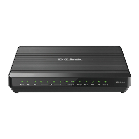
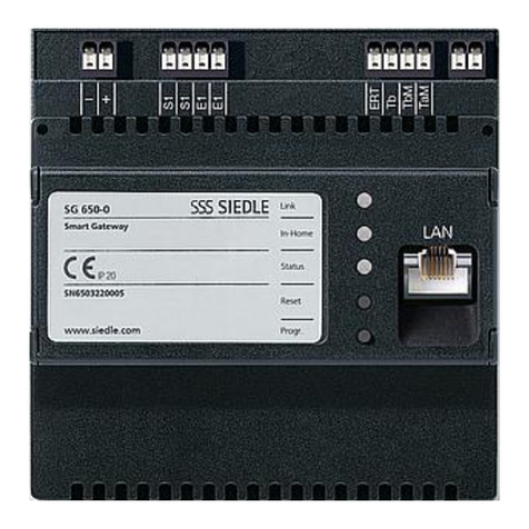
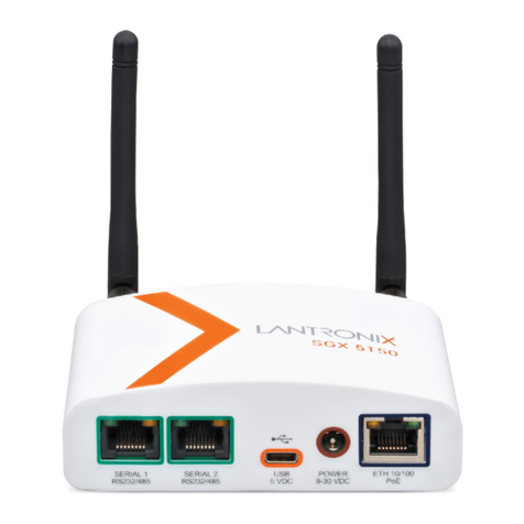
Chilicon Power Gateway CP-100 User manual

CHILICON POWER GATEWAY
Advanced Microinverter Monitoring and
Home Automation Gateway
(CP-100)
Congratulations on your purchase of this
Chilicon Power Gateway. It is the most
sophisticated Gateway available in the
industry for solar system monitoring.
OVERVIEW
The CP-100 Gateway is capable of monitoring any
Chilicon Power microinverter, assisting with the
array setup and creation of the installation for Cloud
monitoring purposes. And it can do a lot more on
the home automation front by monitoring an entire
home power consumption and/or generation.
Thanks to its wireless connectivity, it is also able to
serve as a basic home alarm security controller.
For warranty reasons, Chilicon Power
microinverters should always be installed with a
Gateway which enables their firmware to be
upgraded if necessary.
MICROINVERTER MONITORING SETUP
The first step is to electrically connect the
microinverters to the panels and then to the grid.
Wait for the microinverters to be DC powered with
enough sun light (LEDs will be continuously blinking)
before turning on the AC grid.
After the AC is turned on, the next step is to bind the
inverters with the Gateway.
Connect the Gateway to a power outlet and wait
until it is finished booting. If this is the first time the
Gateway is powered, it will request you to register
this new installation with the Cloud. This enables
monitoring on the web at
http://cloud.chiliconpower.com. The
system owner and installer email addresses are
required to add this new installation to their
respective accounts. If an account does not exist
yet, it will be created using the email address. Once
the new installation registration form is filled out,
press the save button.
POWER OUTLET SELECTION
The next step is to find all the inverters and bind
them to the Gateway so they can start relaying
telemetry data. To do that, go to the settings screen
by pressing the Menu button on the home
screen. The first step is to find a suitable power
outlet that is in phase with the inverters since
inverters only use one of the two lines and neutral
to communicate. So on average, half of the outlets
will have the line used for communicating with the
inverters and the others won’t. If you desire to
connect the Gateway to a power outlet that is on
the wrong line, simply swap the two lines on the
solar array so that the right one will now be in
common with that outlet. In order to survey which
outlet is suitable, use the “survey socket” feature of
the Gateway by pressing the “Advanced Settings”
button and then the “Survey Socket” one .
The PLC socket evaluation will check the current
outlet for each phase and select the one with the
strongest communication to the inverters. If the
socket survey returns with a message indicating the
wrong phase, it is strongly advised to swap the
power lines on the array (simply swap the two lines
feeding into the disconnect box or the main panel).
BINDING OF INVERTERS TO THE GATEWAY
To bind inverters, on the settings screen, select the
Inverter Wizard button . In the first box, enter
the total number of microinverters to be bound to
the Gateway (same as the number of inverters
installed) and the press start. The Gateway will find
all the inverters and bind them after a few minutes.
INVERTER ARRAY CONFIGURATION
The last step in setting up the inverters is to create
the array layout and to assign the inverters to their
correct location in the array. Proceed back to the
home screen and click on the gauge in the top right
quadrant of the screen. If this is the first time and
there is no array configured yet, the new installation
array setup dialog box will pop up.
This dialog box assists with the creation of a
rectangular array or an irregular set of rows. For
instance, to create a triangular array of 10 panels,
one would enter the number of rows to be 4 and
then on the next line, the size of each rows as
follows: 1.2.3.4. The next set of buttons is to specify
the orientation of the panels that will be generated.
If there is a mix of landscape and portrait
orientation, the array will have to be built in two
steps by making it with two sub-arrays. The last
check box “Add new array to existing array”” should
be checked for that purpose if you want to add this
new array to any existing one (else this new array
will replace any existing one). Here is the result of
the previous example (triangular array of 10 panels):
The next step is to arrange the array by either
moving panels around or swapping them. If the
array has the right topology, then you only need to
swap panel IDs around. Press the “Toggle Swap
Mode” button to enter (or leave) the swap mode.
Then select a two panels and their location will be
swapped. The default mode of operation (instead of
the swap mode) is the Pan & Zoom mode. The mode
is shown in the top left corner. In “Pan & Zoom”
mode, select one or more panels by tapping on
them or drawing a selection rectangle around them.
To move the selection around, press on the display
for about 1.5 seconds. The “Drag Mode” will appear
in the top left corner. Then just move the panels in
the desired location. Extra panels can easily be
deleted by selecting them and pressing the “Delete
Modules” button.
If the inverter of a panel has to be replaced, add a
new array, swap the panel IDs (which are really the
inverter IDs) and then delete the extraneous panel
that was added to fetch the new ID.
SOLAR SYSTEM MONITORING USER GUIDE
Here is the main home screen of the Gateway:
It has four quadrants and two buttons in the bottom
right corner (the “Arm” button is only present when
a home alarm security system is configured).
The top left quadrant shows the date. Press on it if
you want to change the format of the time and date.
The bottom left quadrant shows an animation of the
energy flow between the solar array, home (and grid
in the case a consumption monitoring device is
installed –highly recommended!). After some time,
it switches to another graphic showing the total
generation or consumption since the system was
installed.
The top right quadrant shows the gauge with one or
more needles (in case an extra monitoring device is
installed) depicting the instant power generated or
consumed. Pressing on it opens another screen that
shows the configuration of the array with each
individual panel’s production. Other parameters
may be selected and displayed for each panel (like
voltage, temperature, grid voltage, …). This screen
may be disabled in the settings to simplify the end
customer view of the system.
The bottom quadrant is a live graph of the power
generated (and consumed if an extra monitoring
device is present) throughout the day. Tapping on it
expands the graph to a full screen view. Swiping to
the right shows the previous day.
INSTALLING Z-WAVE HOME ENERGY METER
PAIRING THE HEM (HOME ENERGY METER)
The first step is to pair the HEM with the Gateway
so that they can communicate with each other over
the Z-Wave wireless network. It is easier to pair
HEM with the Gateway BEFORE installing them in
the circuit box or disconnect panels. This ensures
there are in range of each other and that the
wireless link is strong. Only Gen2 (DSB28-ZWUS) and
Gen5 (AEOZW095-US) Aeotec Home Meter Energy

are currently supported by the Gateway but we
highly recommend to use the Gen5 version since it
is more reliable and has better RF range.
From the home screen, press the Menu button .
On the Settings screen, press “Advanced Settings”
and then “Measurement Setup” . The first
step is to enable the Z-Wave communication
hardware on the Gateway if that has not been done
yet. For that, make sure the box in front of “Enable
Z-Wave communication” is checked (a dot inside the
box indicates it is checked). Below it will list the
paired devices which at first will show that there are
no devices paired yet.
The next step is to add the HEM to the list of paired
devices. Press the “Add” button and then press the
button on the back of the HEM device once. If your
meter has been successfully paired to your network,
its light will remain solid. If the pairing was
unsuccessful, the light will blink. If that is the case,
try repeating the procedure again.
Once the HEM is paired, you will be prompted to
specify the number of clamps used (usually it will be
2) and whether the HEM is used for generation
metering (PV array only) or consumption (net home
metering or any home appliance). After exiting that
window, the new paired device should show up in
the list of paired devices. Note each HEM is
associated with an ID number.
DEFINING LOGICAL METERS
The next step is to define the logical meters. They
are called logical because they are not physical
hardware but based on a mathematical expression
containing HEM reported valued. Logical meters are
used to record and display the information gathered
by the HEMs. To set up, press the “Manage Power”
button. This opens up the logical meter setup. The
first UI object is a pull down menu showing the list
of defined logical meters. At first, there are none, so
press the “New” button to add a new logical
meter. Typically, you will want to add two logical
meter per HEM. One to measure the instant power
and one for the total energy harvested (the sum of
powers over time).
EXAMPLE OF LOGICAL METERS FOR NET METERING
Let’s assume you have installed a HEM to measure
the entire house consumption (a net meter). Let’s
first setup a power meter. For that, let’s called the
new logical meter “Home Power”. Enter that in the
appropriate box. Then select the type as “Cons.
Meter” for consumption meter.
Under expression, enter the expression that sums
up the two clamp power values. For that, use the
“node ID-clamp-param”pull down box and select
“N4-1-W” assuming the HEM node ID is 4. Then
press “Insert Device” and it will add the term in
the expression box. Then click on the expression box
and a keyboard will pop up. Press the “+” key to add
another term to the expression. Then add the
second clamp power measurement by selecting
“N4-2-W” from the pull-down box and press “Insert
Device” again. The expression is now complete.
In order to tell the Gateway this is the meter of the
entire home (net meter), we check the box “The Net
Meter”. Since the power measurement is an instant
measurement, we also check the “Show Gauge
Needle” box so that it appears on the large gauge
display on the home page. In addition, we can plot
it on the graph by checking the “Plot on Graph”
checkbox.
Now that the Home Power meter is setup, let’s
setup the Home Energy meter that measures the
total energy ever consumed (or produced) as well as
the daily usage (or production). Again, we press
to add a new logical meter. Under the name, enter
“Home Energy”. The type is also “Cons. Meter”.
Under expression, enter “(N4-1-kWh)+ (N4-2-kWh)”
to sum up the energy from both clamps. For the
energy meter, check the “Energy Measurement”
box and the “The Net Meter” one as well for this
example. No need to check the other boxes because
the gauge display and the graph are for displaying
power.
COMMON MISTAKE
If you do not pay attention to the current direction
on the clamps when installing the clamps of the
HEM, there is a 50% chance that the power
measurement for the two clamps will cancel each
other leading to unexpected power measurements.
If that is the case, either reverse the current
direction of the clamps or simply change the
expression by using a “-“ in front of the clamp that
is reversed.
SETTING UP HOME SECURITY
The Gateway is also capable of acting as a basic
home alarm security controller thanks to its Z-Wave
connectivity and software. By installing Z-Wave
devices like door and window sensors as well as
infrared sensors and sirens, the Gateway is able to
detect unwanted intrusion and warn the owner by
ringing the siren.
Different users with different authorization codes
can be programmed to enable tracking in and out of
the home for instance.
In the future, the Gateway will also accommodate
for lighting control based on human presence and
other programming.
FEATURE ACTIVATION
On the Settings screen, press “Advanced Settings”
and then “Home Security Setup” . First
check the “Enable Home Security” box to tell the
Gateway we want to activate the Home Security
feature.
MANAGING USERS
By default, a user called “Default” is created with
the password 13579 and admin permissions
(meaning it has access to all controls). You should
change the default user’s name and passwords to a
more appropriate one. To manage users, press the
“Users” button then select the user from the pull-
down box and select an action. To modify the name,
password (called code on the Gateway) and
permission of an existing user, select the “Edit”
button . To create a new user, press the “Add”
button . And use the “Delete” one to remove
a user.
There must always be at least one admin in the
system to be able to modify the setup. Only users
with admin permission are allowed to modify users
and devices.
MANAGING DEVICES
The next step is to pair sensors and at least one siren
with the Gateway (if there is no siren, the alarm
won’t ring). Press on the “Devices” button to start
setting up those devices. Then select the “Add”
button . Press on the button of the sensor and
wait for a few seconds until it binds with the
Gateway. The “New Device” window will then open
up. First enter a descriptive name for the newly
bound device. Ideally, it indicates the location of the
device and its type. Examples of good names would
be “Garden door”, “Front door”, “Garage door”,
“Kitchen window”, … Below the name are the
different options available that depend on the type
of sensor paired. You may decide to have some
sensors not trigger alarm in certain modes or to not
record events for instance. The “Delayed Trigger”
gives a 60 second delay to any intruder to turn off
the alarm system by entering the proper pass code.
This is useful when you open your front door and
don’t want the alarm to ring immediately but give
yourself a bit of time to disarm the system first.
The “edit” and “delete” buttons under
“Device Setup“ work as expected to change the
attributes of a device and to delete the device
respectively.
ALARM ACTIVATION
The alarm has two main modes: activated or de-
activated. When it is de-activated, it is not turned on
and will never ring the siren. When it is activated,
any sensor programmed to do so will trigger the
alarm if opened.
To switch between activation modes, go to the
home page of the Gateway and press on the “Arm”
button in the bottom right of the screen. It
should be green if none of the sensor is open. If any
sensor is already open, it will be yellow . If trying
to arm then system when a sensor is open (yellow
icon), it will first ask you to confirm that that sensor
won’t be used to trigger the alarm until it is re-
armed with the sensor closed.
When the alarm is activated, an icon of a red disarm
lock is displayed. Press on it to disarm the alarm
and it will ask for your pass code. If the pass code
entered is correct, it will disarm the alarm and
record the event.
FURTHER SUPPORT
If you have further questions or if this document is
not clear enough on certain aspects, please email
support@chiliconpower.com and you will get a
response within a day.
For a list of compatible Z-Wave devices, refer to:
http://www.chiliconpower.com/products/gateway
Table of contents
