Chilton CM2-4 User manual


CM 2
Mik-El / Chilton Page 2of26
Serial Number._________
Date of Purchase. _________
OPERATING INSTRUCTIONS
CM2-4
Guarantee
This Audio Mixer is guaranteed against any defect in material or workmanship for a period of
twelve months from the date of purchase. During this period we undertake to supply
replacements free of charge for any parts which may prove on examination to be defective
provided that such defectiveness is not the result of misuse, accident or modifications. The
mixer or units thereof will be repaired or replaced free of charge, including labour, if
consigned, Carriage Paid, to the manufacturer or agent. The mixer, if sent by carrier, should
be returned in the original packing carton. The manufacturers have no on site service or
maintenance facilities. in special circumstances, at the discretion of the manufacturer or
agent, arrangements are possible, provided travelling and labour costs are paid.
MAGNETIC TAPES LTD., Chilton Works 6-8 Wolsey Rd.,
ASHFORD Middlesex, U.K.
Telephone: 0784 247124 Telex: 912881G MTL

CM 2
Mik-El / Chilton Page 3of26
CHILTON CM SERIES
General Instructions.
After opening the packing case, lay horizontally, control side up and slide out.
Then check for any visual damage.
The Power supply (PS30) is packed separately, complete with 2 leads:
1. Mains cable with moulded on connector to PS30.
2. 1-6 metre spire wrap connecting cable.
Check voltage selector on Power supply agrees with mains supply. (Remove PS30 cover)
Connector cable 2 to PS30 and console respectively and secure 8 pin connectors with 2 spring
clips provided. Connect to mains and switch on. If the fuse is OK, the meters will illuminate
and Channel LED's glow and then go out. The LED's on the Power supply are connected to
the +15v DC 1A (Electronic supply) and gives a direct indication of this output.
800mA 20mm Anti-surge 110-120v
400mA 20mm Anti-surge 220-240v
PPM. For operators not familiar with the Peak Programme Meter, each division is 4dBs.
Reference level of 0dBm (0.775v RMS) is 4. It has very rapid needle movement -indicates
Peak Level -and an electronic hold, giving a decay of 3 seconds from 7 to 1 on the scale.
Pre Installation Checks.
The general function of the console can be checked using the internal oscillator.
Output modules M2 -M3: (or generally to M42 -M43 4 Group)
a) Switch oscillator to 1kHz (LED on) press "SLATE" then set Group faders 1 and 2 to ref.
0dB. PPM will indicate "4" or VU -4dB. (This level should hold within 1dB from 40 to
15kHz). Increase both faders to read PPM "5" or 0 VU, then peak LED's below, meter
should now illuminate. To adjust for other levels, see circuit diagrams PPM-R34 VU-R1.
b) Depress MONO button (M3) this will give very small change in meter level. Pulling
down either group faders will show a drop of 6dBs. PPM. 2dB VU.
c) Auxiliary output: Turn down cue loudspeaker volume control, depress A1 button (M3)
hold down AFL button (A1) turn up A1 Master gain to approximately 3 o/c. This will
indicate PPM "5" or 0 VU. repeat with A2. (and A3)
d) Talkback: Group faders ref. 0dB. TB gain control fully clockwise, SLATE button down.
Depress TB MIC button then talking at normal level both group peak LED's will indicate.
* Remove both foam blocks retaining front corners of CONSOLE

CM 2
Mik-El / Chilton Page 4of26
Input Module M1 (and M41)
For this test 1 male and 1 female XLR connectors are required.
Solder pin 2 to 2 and pin 3 to 3. The cable length appropriate to the console size. Screen wire
is not necessary. Plug the female XLR into Aux. 1 output and male XLR into Line input of
M1. (Osc. 1kHz A1 button down only) Adjust A1 master output to 0dBm. (PPM "4" VU -4)
a) Group and channel faders ref. 0dB
b) Pan central
c) Channel to LINE +48v off
d) Set Channel line input gain to 0dB
e) Channel ON
This will give approximately +2dBm (PPM "4 1/2" VU -2dB) on group meters.
Increasing this input level (Master A1 and AFL) by 4dB to +4dB will trip on Channel
LED.
Depressing PFL button will indicate 0dBm on PFL meter independent of Channel
fader.
High pass 70 Hz filter will drop level by 6dB @ 40Hz ref. 1kHz
The EQ section can be checked using spot frequencies 10 kHz for HF 100 Hz for LF
and 100 -1kHz for Mid.
Microphone Input: Set up as for Line with 0dBm input
a) Pad in.
b) Set channel Mic input gain to 20 dB Control fully anticlockwise
c) Switch channel to MIC
Group meter will now read approximately 0dBm.
Frequency check 40 -15kHz within 1dB

CM 2
Mik-El / Chilton Page 5of26
Input module M4 (or M44)
The test lead suitable for M1 inputs can be used only for M4 balanced inputs. Unbalanced
Line and Phono inputs require different pin connections as follows:
Male XLR connector, link pins 2 and 3 to: Female XLR into Auxiliary 1 output and Male
XLR into either stereo input and depress relevant input selector switch L1 or L2. (Osc. 1kHz
A1 button down only). Adjust A1 master output to 0dBm.
a) Group and Channel fader ref. 0dB (set Balance control to "0")
b) Switched input gain control 0dB
Pressing the PFL button will show PPM "4" or VU -4dB on RH meter. Increase input
level by 4dB via A1 control channel, Peak LED will illuminate. Release PFL, reduce
input to 0dBm.
c) Press L and R and CH ON button. (M44 Press 1-2 or 3-4 or LR +CH ON) This will give
approximately +2dBm (PPM "4 1/2" VU -2dB) on group meters. No change will be
observed in MONO mode. A similar procedure can be used for Phono input, but input
level via A1 should be reduced to approximately 9 o/c to give 0dBm on PFL meter.
To test Balanced Line inputs: L1 and L2 are Left and Right channels respectively.
Mik-El / Chilton Page 6of26
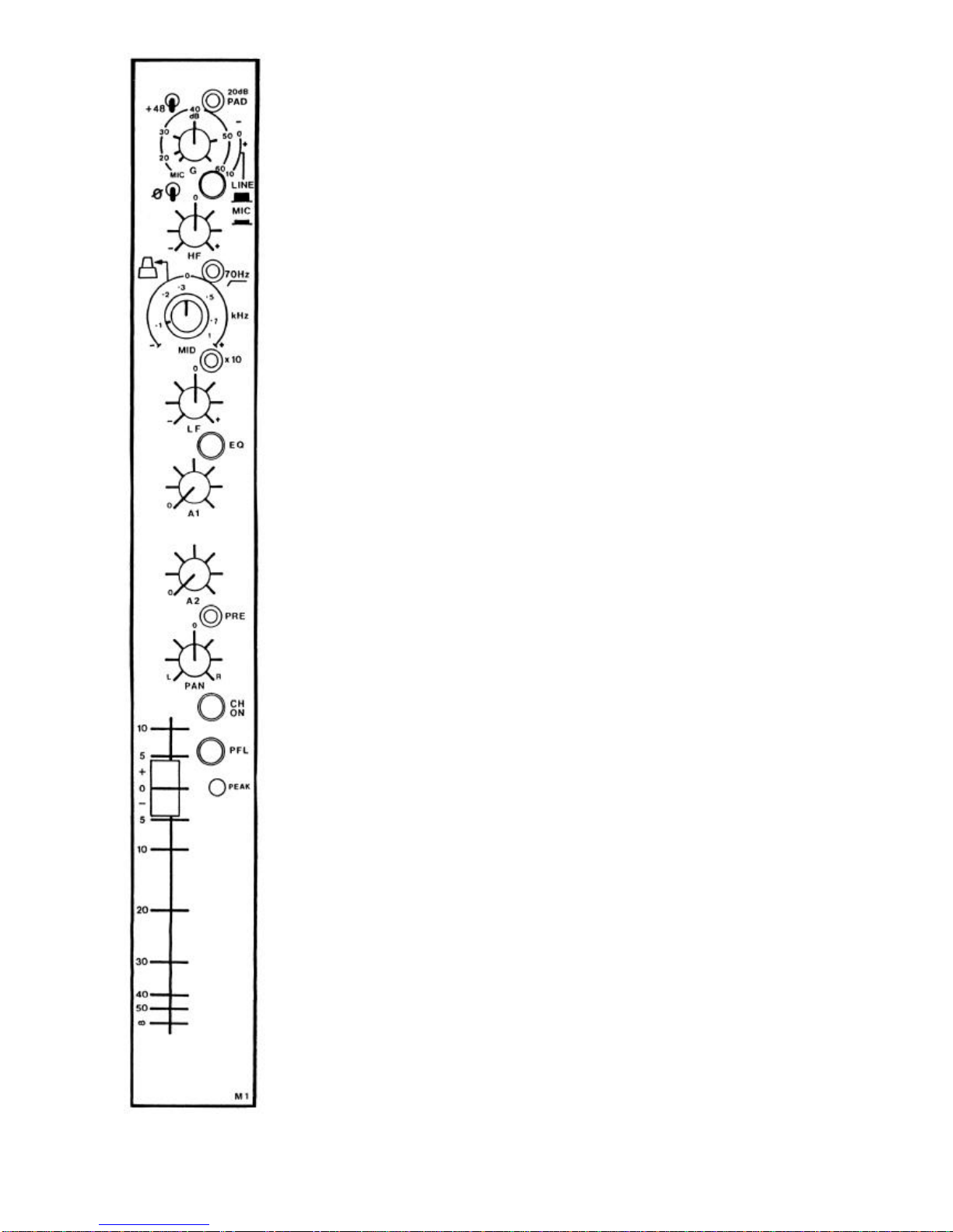
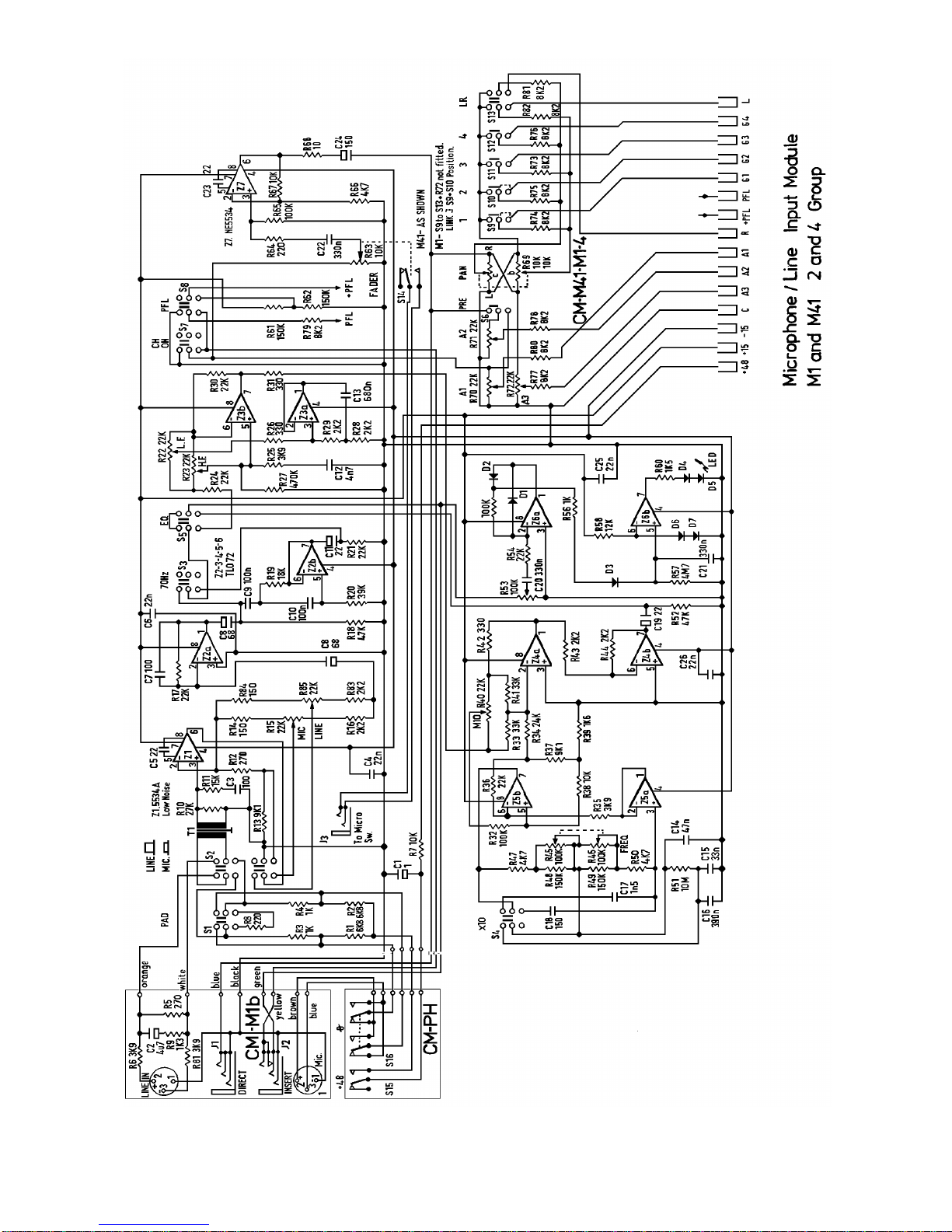
Mono Microphone and Line Input. M1
Dual concentric control, lower Microphone top Line Microphone gain is variable between
20dB. A 20 dB pad or attenuator is provided. Thus should be used when the gain is
around the 20-30dB mark. A 48V supply is available for capacitor microphones which are
not self powered. The accidental use of this supply on dynamic types will not cause
damage. The microphone phase change switches should all point in the same direction
unless a phase problem is suspected. Line gain is variable between +10dB to -20dB
therefore with Channel and Group fader at ref. 0-10dBm to +20dBm input will give 0dBm
on Group meters.
High Frequency shelf control: +-15dBm at 10kHz centre (indent flat)
Switchable High Pass Filter effectively removes low frequency components below 70 Hz at
the rate of 12dB/octave Pre-EQ
Dual concentric mid sweep control. 100 -10kHz.
Lower control knob sweeps 100Hz to 1kHz or with 10 switch depressed 1k -10kHz
(overlap provides up to 13kHz)
Top control knob: Boost or cut +-15dB at frequency selected. Centre Indent flat (Q 1-5)
Low Frequency shelf control: +-15dB at 100Hz. Centre indent flat.
Equalisation in circuit with EQ button depressed (Green fisheye).
High pass filter independent of this control.
Auxiliary 1 Send. A 1 Pre channel fader (can be linked to Post)
Auxiliary 2 Send. A 2 Switchable Pre or Post channel fader.
Panning is provided between Left and Right group outputs or can be used as a Group
Routing switch.
Channel On. Button down (Green fisheye).
Note: Both Auxiliary Sends are muted with button UP.
PFL Pre-Fade Listen switch (lockable fisheye) routes the Channel to Cue Loudspeaker,
Headphones and Control room monitors without affecting the Group output. Illuminates a
Green LED on the M3 Monitor module.
Peak Level indicator is illuminated if the channel level approaches +4dB. This is 16dB
below clip point; allow for subsequent EQ adjustment. Note: (Pre-set adjust -10dB to
+20dB)
104mm Linear fader. Very high quality plastic conductive with rubber end stops. Micro
switch can be fitted for self start or monitor mute.
Rear Panel. Balanced and floating Microphone or Line inputs
Microphone Input: Connections see block diagram. Suitable for 200 ohm type
microphones.
Line Input: Balanced input connect as diagram. Unbalanced input Live to pin 2 Common
to pin 3 Screen only pin 1
Direct Output: Jack tip Live. Sleeve Common. May be wired Pre Fader
Insert: Jack 3 pole type. Tip Return. Ring Send . Sleeve Common.

Mik-El / Chilton Page 7of26
Stereo Line or Phono Input. M4
L1 and L2 select either of two unbalanced Line or Phono inputs.
See M4 module input configurations drawing.
Switched Input level control. When magnetic cartridge pre-amps are fitted,
each has a Gain pre-set accessible by lifting up the meter bridge panel. to
adjust, set level switch to 0dB Channel fader to your required reference
(normally 0 or +10) and Group faders to 0. Adjust pre-set to give required
level on output meters from tone on test record.
Balance control will increase gain by max 3dB to Left or Right channel as
indicated on scale.
Auxiliary Send 2 takes a mono mix of L and R channels Pre fader (Can be
wired Post)
Auxiliary Send 2 takes a mono mix of L and R channels Pre or Post fader
(switchable)
Stereo to Mono Push button
PFL. Mono summation of L and R, otherwise as M1 PFL
Peak Level Indicator. illuminates when left, right or both channels approach
+4dB, otherwise as M1
L. R. push button selection to Group outputs.
104mm Stereo Fader. Otherwise as M1
Rear Panel:
Line In 1-2: See block drawing as M4 Input drawing
Insert L and R: Jacks 3 pole. Tip Return. Ring Send. Sleeve Common
Mik-El / Chilton Page 8of26
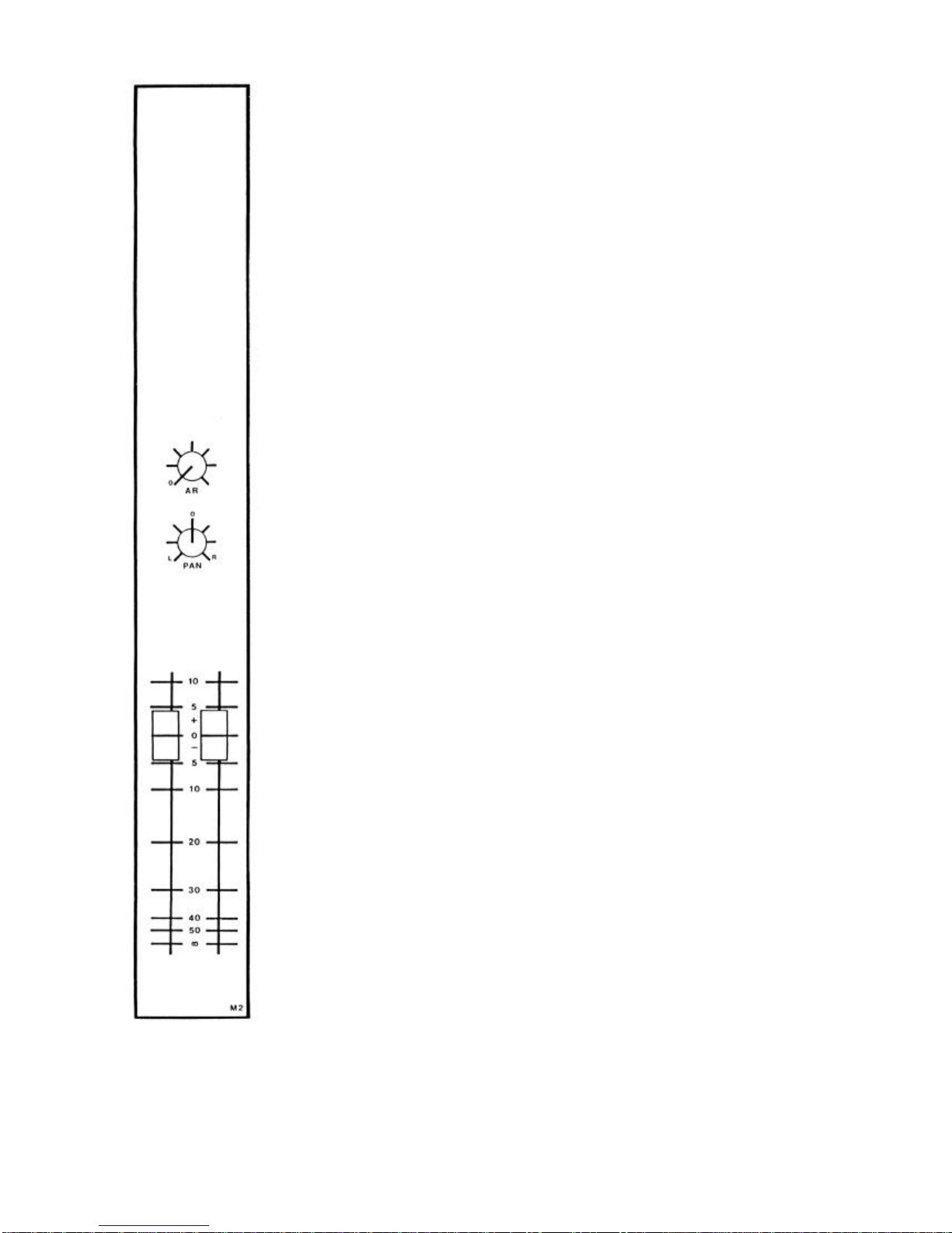
Master Stereo Output. M2
This module houses both Left and Right Mix and Output amplifiers and the Mono
output.
Provision is made to retro fit 3 balanced output transformers for L1 L2 and Mono.
Separate auxiliary return gain controls with direct access to Left and Right mix bus.
Aux return: Jack 3 pole Tip Left Ring Right Sleeve Common
Inserts: Jack 3 pole Tip Return Ring Send Sleeve Common
The fader knobs are off-set so may be spaced apart for sub-grouping in Mono or
closely spaced for Stereo.
Rear Panel:
L1 (left) L2 (right) and Mono outputs see block diagram for connections. Note: Pin
3 is Common or 0 volts in the unbalanced mode and should not be connected in
outer screen. When possible Live pin 2 and Common pin 3 should be screened and
terminated at one end only to pin 1 (Connects to console frame)
Mik-El / Chilton Page 9of26
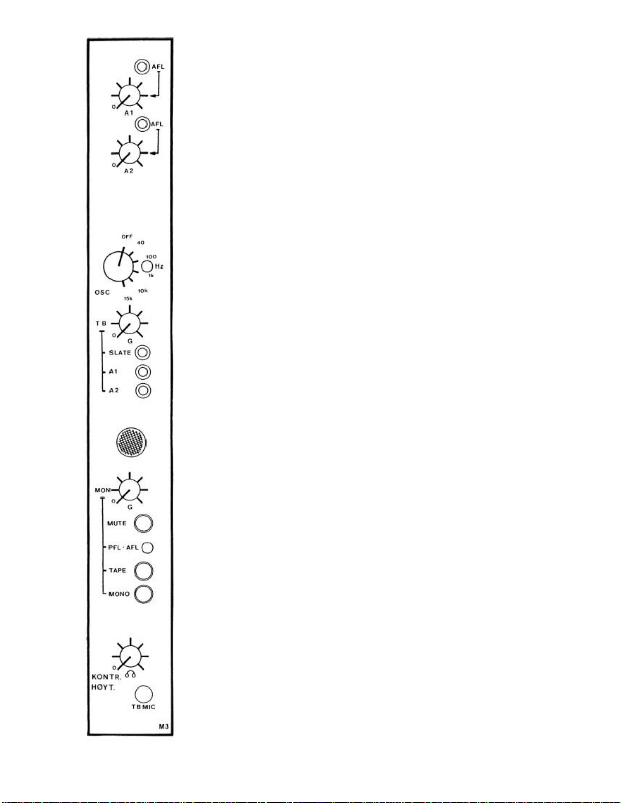
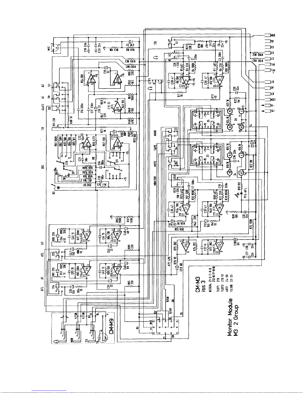
Master Monitor. M3
A1 Master auxiliary output level control Pre channel fader. The AFL After Fade
Listen button (hold only) routes A1 to headphones, monitors and PFL meter.
A2 Master auxiliary output level control Pre or Post channel fader with AFL
switch
Osc. Low distortion test oscillator. LED indicates ON positions.
Talk back microphone gain control "G" is activated by "TB MIC" hold only
button and routed at Line Level to rear XLR connector when Slate A1 and A2
buttons are not assigned. Both Oscillator and Talk back can be used
independently or together. For example: assigning 40Hz and Talk back to slate
(group outputs) both track indent and fast wind search tone can be recorded.
Note: External Talk back is muted when any button is assigned.
MON control "G" is for control room or studio monitor loudspeaker level.
MUTE: This mutes the monitor output only.
PFL: Green LED indicates Monitors are in PFL mode via channel PFL buttons or
FL for Auxiliary Outputs.
TAPE: Selects stereo or mono tape returns.
MONO: Mono output summation of left and right groups.
HEADPHONE level control follows monitor output but is not muted.
"MIC" button also mutes Monitor signal in all modes.
Rear Panel:
A1 -A2 -TB See block diagram for connections.
Headphones: Jack 3 pole. Tip Left. Ring Right. Sleeve Common.
Parallel to jack socket on console front.
Mon: Monitor output wired as headphones.
TR Jack 3 pole. Tip Left. Ring Right. Sleeve Common.

Mik-El / Chilton Page 10 of 26
MODULE SERVICE.
To removed or transpose modules, a pozidriver size 2 screwdriver is required.
Procedure:
First, remove lower fixing screws on meter bridge front panel, (3 off 10 inputs -4 off 16 inputs) complete
with fibre washers. Then lift to a horizontal position and fix. NOTE (xx)
Remove rear Jack socket fixing nuts* on module to be changed or removed and front 2BA black
countersunk fixing screw. Remove internal mini jacket plug, if fitted. Lift up front of module using Pan
or A2 knobs (NOT FADER KNOB) until fader body is just clear of case; pull forward to release rear
connectors from back panel (rear label will drop clear) finally hook round meter bridge tie rod to pull
clear. Reverse procedure to replace.
Always check rear connectors are fully engaged into rear panel before pressing module fully home into
the Bus connector. If problems are experienced in replacing the far left hand module try removing both
middle and bottom rear panel fixing screws.
When removing internal connectors on M2 or M3 modules use a pair of pliers, DO NOT PULL CABLE
(applies to M45-M42a-M42b-M43 on 4 Group)
* Replace finger tight only.
Blank panels: These have a small movement in the rear fixing holes to align with existing modules.
FIRST ISSUE CM2 MODULES
M1 Module
a. Delete +48v Phantom Power switched.
b. Delete Phase reverse switch.
c. Mid x 10 switch. 100 -1kHz range button down.
d. Balanced Line input Jack socket. Tip + Ring -Sleeve Common
M4 Module
a. LINE IN 1 Jack socket. Tip Left. Ring Right. Sleeve Common
M3 Module
a. oscillator frequency 10kHx incorrectly printed 1kHz
xx If difficulty is experienced when replacing fixing screws (locate centre screws first) slacken off upper countersunk
screws first.
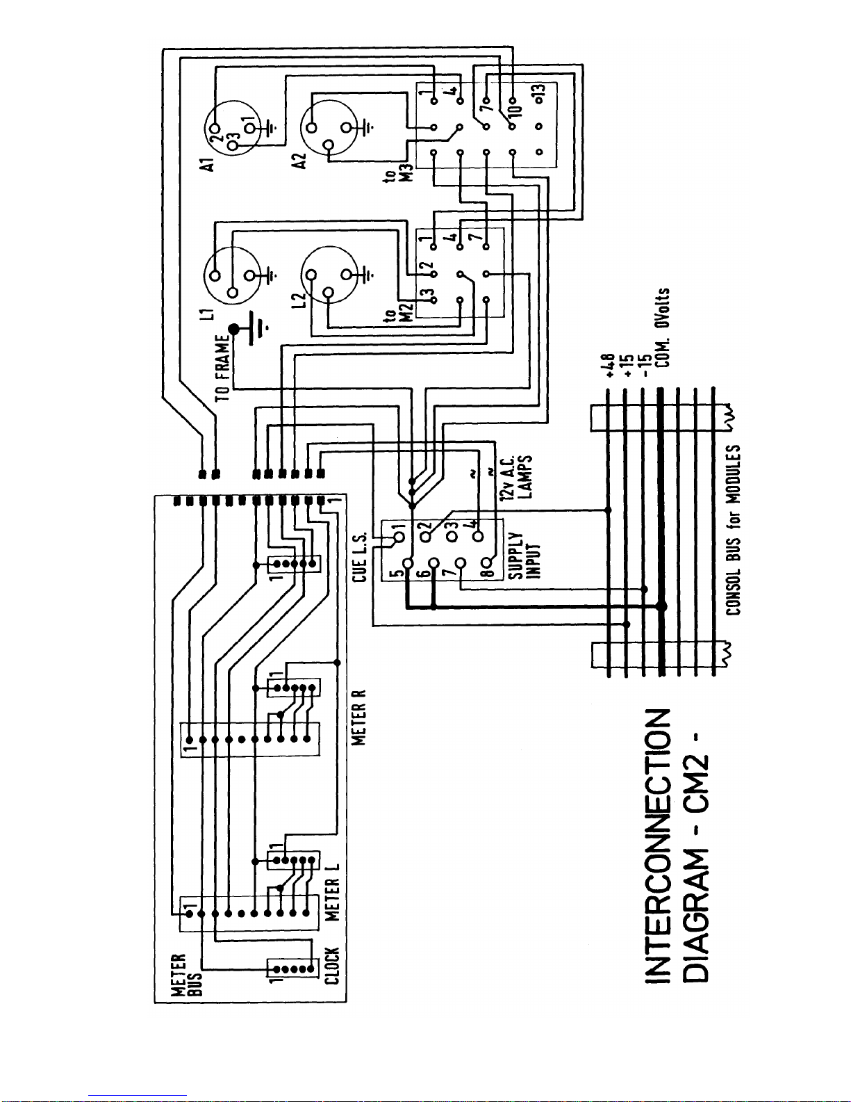
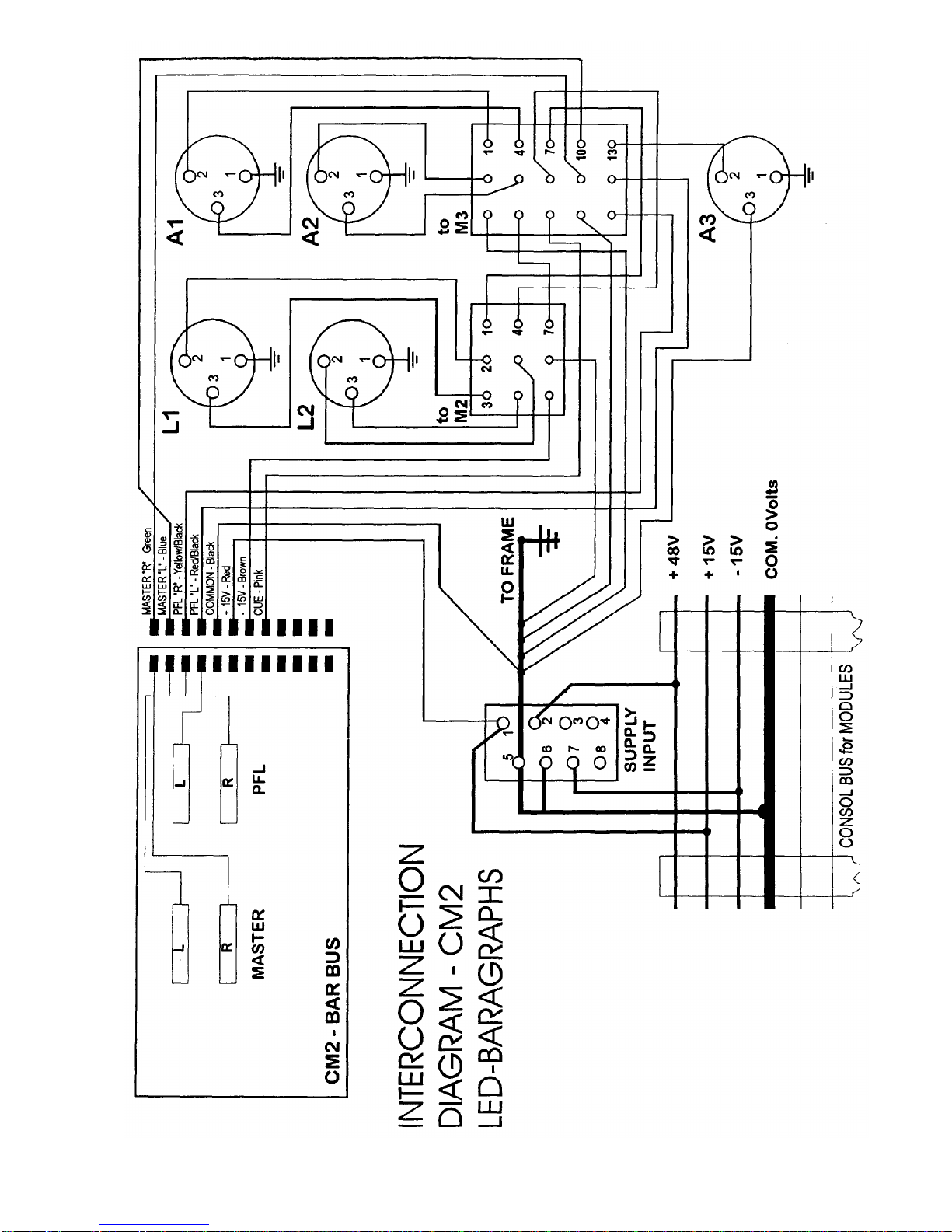
Mik-El / Chilton Page 11 of 26

Mik-El / Chilton Page 12 of 26
Mik-El / Chilton Page 13 of 26
Mik-El / Chilton Page 14 of 26

Mik-El / Chilton Page 15 of 26
Mik-El / Chilton Page 16 of 26

Mik-El / Chilton Page 17 of 26

Mik-El / Chilton Page 18 of 26

Mik-El / Chilton Page 19 of 26
Mik-El / Chilton Page 20 of 26
Table of contents
Other Chilton Music Mixer manuals


