ChinaLight Solar CLS-230P User manual

Solar Power System
Installation Manual
Polycrystalline Solar module
ChinaLight Solar Co. ,Ltd.
No3, Xingguangsan Street,Opto-Mechatronics Industrial Park,Beijing,P.R.China
Postcode:101111
Tel:+86-10-8150 6588
Fax:+86-10-8150 6120

• Please read this manual carefully before installing the system and carry out the
installation procedures correctly.
• This manual does not list all precautions needed for safe work. Be sure to follow
OSHA guideline.
• This manual provides guidelines for installation, but it does not guarantee the
quality of installation work. Please complete all work in a responsible and
professional manner. Electrical work should be performed by a qualified electrician.
THE MOUNTING SYSTEM HAS BEEN LOAD TESTED AND VERIFIED BY A
PROFESSIONAL ENGINEER. THIS INFORMATION CAN BE PROVIDED UPON REQUEST.
ChinaLight Solar Co. ,Ltd.
No3, Xingguangsan Street,Opto-Mechatronics Industrial Park,Beijing,P.R.China

1. FOR SAFE INSTALLATION WORK............................................................................................4
1.1 CAUTIONS REGARDING INSTALLATION OF SOLAR POWER SYSTEMS .........................5
1.2 MOUNTING SYSTEM.................................................................................................6
1.3 PV MODULES...............................................................................................................7
2. POINTS TO CHECK WHEN SELECTING THE INSTALLATION LOCATION ................................10
2.1 CONDITION OF HOUSE WHERE SOLAR POWER SYSTEM IS TO BE INSTALLED ..........10
3. SPECIFICATIONS...................................................................................................................11
3.1 SOLAR MODULE AND ARRAY SPECIFICATIONS MODULES: CLS-230P .......................11
4. PARTS ..................................................................................................................................13
5. POINTS TO CHECK BEFORE INSTALLATION WORK ..............................................................14
5.1 UNPACKING AND CHECKING PARTS..........................................................................14
5.2 MATERIALS AND TOOLS YOU WILL NEED..................................................................14
6. INSTALLATION WORK..........................................................................................................16
6.1 PREPARING SHINGLE ROOF FOR INSTALLATION .......................................................16
6.2 CHECKING LAYOUT....................................................................................................16
6.3 INSTALLING THE FLASHINGS (OPTIONAL) .................................................................16
6.4 Mechanical Installation .............................................................................................17
6.5 SYSTEM GROUNDING................................................................................................22
6.6 INSTALLING MODULE SUPPORT RAILS......................................................................22
7. L IMI T ED WA R R ANT Y .....................................................................................................23

1 FOR SAFE INSTALLATION WORK
Warning
• Do not cut or modify Mounting System. Doing so is dangerous. Safety cannot be
guaranteed.
• Stop work during stormy weather. Solar modules can be caught in the wind,
causing you to fall.
Caution
• Never step or sit on the glass surface of a solar module. The glass may break,
resulting in shock or bodily injury. The module may also stop generating power.
• Always use the supplied parts to attach the solar modules and mounts. Use of
weaker parts, such as screws that are too short, is dangerous and may cause the
solar modules or mounts to fall.
• Always use the specified tools.
The solar modules or mounts may fall if the installation is not strong enough, for
example when parts are not tightened sufficiently.
• Regardless of whether you are working on a new or existing roof, never allow the
sheathing to become wet. Protect
the sheathing from rain during the installation. Failure to do so may cause leaks.
• Always use the specified materials.
Use of other materials is dangerous. Materials other than specified can reduce
performance and can cause leaks, shock, and so on.
• Do not modify or cut parts.
• Do not install system in a location within 0.3 miles from the ocean or any salt
water.
• Do not install in corrosive locations classified C5 by ISO.
• Protective earth grounding of the individual photovoltaic modules is achieved by
the secure of the modules to the mounting frames. The assembly instructions should
be closely followed, in order to ensure a reliable ground connection.
• The framing system has only been evaluated by TUV for use with the photovoltaic
modules listed in this manual.

1.1 CAUTIONS REGARDING INSTALLATION OF SOLAR POWER
SYSTEMS
This manual contains critical information regarding electrical and mechanical
installation and safety information which you should know before starting
installation.
The information in this manual is based on CHINALIGHT’s knowledge and experience,
however, the information and suggestions do not constitute a warranty.
CHINALIGHT reserves the right to make changes to the product, specifications, or
manual without prior notice.
Do not locate systems near coastal locations or other salt water locations or C5
locations as classified by ISO. Minimum distance is 0.3 miles from the body of water.
Do not locate in a corrosion prone area. The modules and system are TUV listed to
standard IEC61215. The TUV IEC61215 test is performed at 1.5 times the design load
of 30 lbs per square foot, or 45 lbs per square foot. The system has been load tested
by CHINALIGHT to 50 PSF. Building departments often require a design safety factor
of 1.5 or greater for structures. The maximum structural loading listed in this guide,
does not include an added safety factor. Check with your local building department
for code information.
Caution:
1Do not drill holes in frame. Do not cut or modify parts or rails.
2Work under dry conditions with dry tools.
3Do not stand or step on solar module.
4Do not install near flammable gases.
5Do not drop or allow objects to fall onto module.
6Completely cover solar module with opaque materials when wiring to halt
production of electricity.
7Keep the back side of solar module surfaces free of foreign objects.
8Do not use chemicals on solar modules when cleaning.
9Do not wear metallic jewelry, which may cause electrical shock.
10 Do not touch cable electrical contacts.
11 Do not expose solar modules to sunlight that is concentrated with mirrors, lenses
or similar means.
12 Consult local codes and other applicable laws and statutes concerning required
permits and regulations concerning installation and inspection requirements. Install

solar modules and systems according to applicable codes.
13 Product should be installed and maintained by qualified personnel. Keep
unauthorized personnel away from solar modules.
14 Avoid shadowing cells in order to prevent solar module hot spots and/or
reduction in power.
15 Avoid installing modules and mounting system in high corrosion areas.
1.2 MOUNTING SYSTEM
Solar modules are installed on rooftops where there is danger of personnel falling off
of the roof. Scaffolding, stepladders, and ladders may be dangerous and require
caution. The installation of solar modules involves work in high places, take extreme
precautions to avoid falling from roof. To prevent accidents, safety regulations must
be observed. Always take the following precautions to prevent accidents and injury.
1 Take the following precautions before starting work.
• Plan the job and visit the site before starting work.
• On site, do not work alone. Always work with at least one other person.
• Inspect power tools before using them.
2 When conditions make it necessary, tell workers to stop working.
• When it is raining, or there is a strong probability that it will start raining.
• Immediately after rain, and when work areas are slippery.
• When high wind conditions exist, or are expected, or when a high wind warning
has been issued.
• When it is snowing, or when there is snow underfoot.
• When the condition of the scaffolding and ladders are not satisfactory.
3 Wear appropriate work clothes and protective equipment.
• Work clothes for both the upper and lower body should fit well and allow you to
move freely.
• Always wear protective equipment such as harnesses and lifelines.
• Wear a helmet and secure it correctly.
• Wear non-slip shoes. Shoes get dirty when worn on a roof, so keep the soles clean.
4 Observe safety regulations for ascending and descending ladders and
stepladders.
• Before use, always inspect ladders and stepladders to makes sure they are in good
condition.
• Choose a safe spot to anchor ladders and stepladders.
• Always work with a partner. One person should hold the ladder steady.
• Ladders from a first-story roof to a second-story roof are very dangerous. Do not
set up a ladder on a roof. When there is no other choice, straddle the ridge and lay
down a rubber anchor mat, and secure the ladder to the mat. Always have one
person hold the ladder firmly.
• When you use a two-stage ladder, secure it with ropes or stays to prevent it from
sliding sideways, and have two persons hold the ladder steady.

• Use ladders with steps broad enough to permit safe work.
5 When working in high places, wear harnesses and use scaffolding.
• When working at heights of 6 ft or more, use scaffolds or other equipment to
ensure a stable work platform.
• Scaffolds should be designed and erected by a qualified person.
• When it is difficult to erect a stable work platform, install safety nets, wear
harnesses, and take other measures to prevent falls.
• Regulations mandate the use of harnesses. Fasten harnesses securely, and check
that the length of lifelines is 6 ft or less.
• Attach the primary support line securely to a metal fixture installed for that
purpose on a ridge or beam.
6 Install enclosures and covers.
• Install enclosures, guardrails, or covers at the end of work decks that are 10 ft or
more above ground, at openings, and at other dangerous locations.
• When it is extremely difficult to install enclosures, guardrails, or covers, or when
they must be removed to work in that location, install a safety net, wear harnesses,
and take other measures to prevent falls.
7 Protect against falling objects.
• When objects are thrown down from a height of 6 ft or more, appoint a
surveillance person on the ground and warn others about falling objects.
• Do not allow third parties to enter the work area during construction.
• Arrange tools and materials neatly and secure them with ropes, or use bags or
other measures to prevent falling objects.
8 Other
• When there are electric power lines near the roof or eaves, request the power
utility to take advance measures to prevent shock.
• Check the health of workers before starting work.
• Lift packaged modules by grasping both sides of the package. Do not lift by
grasping the band, as the band can break.
• Never step or sit on the glass surface of a solar module.
1.3 PV MODULES
Warning
Wiring work should be performed according to the provisions of the National
Electrical Code(NEC). Grounding work and wiring connections to the inverter should
be performed by a qualified electrician.
The solar array generates electricity whenever it is exposed to sunlight. Be careful
when handling it. There is a danger of shock if you touch the connectors or wires of
the electric cables.
1 Points to check before wiring.

• The solar modules generate electricity when exposed to light. You will need to
wear insulating gloves.
• You will need a multi-meter for volts, amps, resistance and continuity capable of
measuring DC and AC up to 600V and 40A.
• Make sure your tools are insulated.
2 Wiring the solar modules.
• Never step or sit on the glass surface of the solar modules. The glass may break.
• When you install the solar modules on the mount, never allow an output cable to
become caught between the mount and a module frame.
• The solar modules generate electricity when exposed to sunlight, take care not to
short circuit the output cables. The cables can become overheated and their cable
sheaths can melt.
• Ensure the module connectors are fully inserted. There is a risk of malfunction if
they are not pushed in all the way.
• Support output cables so that there is no slack. High winds can blow slack cable
against the mount, damaging the cables.
3 Wiring from solar arrays to the inverter (connector box).
• Follow the provisions of the National Electrical Code.
• For wiring through walls, protect the cables with metal conduits, flexible metal
conduits, or other protection. Failure to do so can result in shock and short circuits.
Always use conduit to protect sections of array output cables that are exposed to
sunlight. For wiring outdoors, protect cables with PVC conduits, metal conduits or
flexible conduits.
• Prevent water from entering or building up in conduit by using waterproof fittings
or duct seal.
• To prevent shock, tape and label the cut ends of array output extension cables (the
side opposite to the connector side) before connecting to solar module output
cables. Further, tape them again after measuring the voltage of each array.
• To prevent shock when you connect the array output cables to the inverter,
remove the tape one cable at a time as you connect the cables.
4 Measuring array output voltage
• See the description of how to measure the output voltage for each array.
• Make sure that all solar modules are exposed to sunlight. (Remove lightproof
sheets, if present.)
• Set the volt meter measurement range to a DC voltage, greater than the expected
measurement (for example 600 VDC).
• Keep the plus (+) solar array output cables away from the ends of the minus (-)
cables. Dangerous arcs can occur. (The array output voltage under normal conditions
(clear skies) can be very high.)
5 Grounding the mount
• To prevent shock, always connect a ground wire from the mounting hardware to
earth.
• Use a minimum #10 AWG ground wire. Run a continuous bond wire to each

module and rail in the array. Refer to section on grounding in this manual.
• Follow NEC 690 grounding provisions.

2 POINTS TO CHECK WHEN SELECTING THE INSTALLATION
LOCATION
Check the following items before starting installation work.
Refer to the inverter installation manual for more information about inverter
installation and electrical work.
2.1 CONDITION OF HOUSE WHERE SOLAR POWER SYSTEM IS
TO BE INSTALLED
INSPECTION OF ROOF STRUCTURE
It is important to inspect the structural integrity of the roof and the durability of the
roof materials. The mounting structure and solar modules require a strong base for
durable and reliable operation in local environments. Always wear a safety harness
when working on the roof. Inspect the roof surface in the area of the installation for
cracks, water leakage, and roofing material quality and uniformity. This is especially
important if the roof is older than 10 years. Inspect the roof for sags and other
abnormalities. A sag or deep depression in the roof may indicate a structural
weakness in the support system that may require correction. The following
illustrations detail typical roof construction as well as old roof problems.
INSPECTION OF THE ROOF SUPPORT SYSTEM
This may require access to the attic. Check that all rafters, trusses and other
materials are in good condition. Check for indication of previous water leaks.
Measure the spacing of the rafters or trusses to confirm the dimensions and prepare
for the system layout. Determine the location of the electrical roof penetration and
wire run, if wiring is planned for this area.

3 SPECIFICATIONS
3.1 SOLAR MODULE AND ARRAY SPECIFICATIONS MODULES:
CLS-230P
1 Array specifications (typical examples)
Array: Layout of series connected solar modules
Solar module CLS-230P
Solar modules 18 20 24 27
Solar power capacity
(kW) STC 4.1 4.6 5.5 6.2
Solar module area (㎡)29.4 32.7 39.2 44.1
2 Individual specifications and dimensions
Module model name CLS-230P
Maximum power 230W
Voltage at
(
)
29.28V
C
urrent at
(
)
7.86A
Open-circuit voltage( ) 37.38V
Short-circuit current( ) 8.31A
Weight 20KG
Dimension 1650mm*990mm*50mm
Rated electrical characteristics are within ±10 percent of the indicated values of Isc
and Voc and within +10/-5 percent of Pmax under standard test conditions
(irradiance of 100 mW/cm2, AM 1.5 spectrum, and a cell temperature of 25°C (77°F)).
Under normal conditions, a photovoltaic module may experience conditions that

produce more current and/or voltage than reported at Standard Test Conditions.
Accordingly, the values of Isc and Voc marked on TUV Listed modules should be
multiplied by a factor of 1.25 when determining component voltage ratings,
conductor capacities, fuse sizes and size of
controls connected to the module output.

4 PARTS
STANDARD PARTS
Part
No. 1 2 3 4 5 6
Name Dock
washer
M8
Bolt 20
Module
mounting
clip
Threaded
tab
M4
Sidecover
screw
Rail
OPTIONAL PARTS
Part
No. 1 2 3 4 5
Name
Cable
support
bar
Cable
clip
Silicone
caulking
Threaded
tab
M8 Bolt
30
5 POINTS TO CHECK BEFORE INSTALLATION WORK
WARNING
• The solar modules generate electricity when exposed to sunlight, so be careful not
to short circuit the output cables. The cables can become overheated and their cable
sheaths can melt.
• Stop working when the surface of the roof is wet. There is a danger of slipping,
falling, and shock.
CAUTION
• Never step or sit on the glass surface of the solar modules. The glass may break.
• Do not twist the solar modules when you mount them (twisting should not exceed
0.1" per 4"). Failures and damage can result.
• When you mount the solar modules on the rail, never allow an output cable to
become caught between the rail and a module frame. Short circuits and fire can
result.
5.1 UNPACKING AND CHECKING PARTS
When you unpack the system, check the model names of the components of each
system and check to be sure that you have the correct number of parts.
5.2 MATERIALS AND TOOLS YOU WILL NEED
Before starting installation work, make sure you have the following materials and
tools on hand (including materials and tools for electrical work).
Materials
tools
Ground
wire
Ground rod Electrical
tape
metal conduit
(to protect
electric cables)
Cable
ties
Pencil
Cordless
drill
Socket
drivers
8 mm & 13
mm
Phillips
driver bits
Drill Screw
driver
set
Needle
nose pliers
Line man’s
pliers
Wire
cutters
Hammer Chisel
Crimping
tool
Knife Tape
measure
Extension cord Chalk
line

Gloves &
safety
helmet
Rope Tool belt Ladders Safety
Harnes
s
Safety
glasses
Air mask Ratchet
Wrench
Measurement
Compass Calculator Solar
insolation
meter
Digital
multimeter

6.INSTALLATION WORK
6.1 PREPARING SHINGLE ROOF FOR INSTALLATION
1. Locate roof rafters or trusses.
Tip: here are 3 options to finding the locations.
A. Locate and measure the locations of the rafters in the attic or at the outside eave and transfer
measurements to the roof.
B. Use a rubber or leather mallet to tap the roof and locate the rafters. This will work with a cap sheet or
composition roof.
C. Scan the roof with a high sensitivity stud finder.
2. Once the rafters have been located, snap a chalk line on every rafter to identify the location.
3. Measure up from the eave 400 mm in at least 3 locations. Snap a chalk line. This marks the location of
the bottom edge of the slider feet.
Note: This line needs to be 5.5 mm away from the nearest front edge of shingles.
4. Measure up from chalk line 20 mm and snap a new chalk line. This marks the location of the bottom
edges of the modules.
5. Measure up from the module chalk line to the desired module length to form the array. Snap horizontal
lines at the measured locations.
6. Mark and layout solar module vertical lines.
Note: modules should not fall in shaded areas.
6.2 CHECKING LAYOUT
1. Before installing sliders, check layout of rails and splices.
2. Place all sliders in desired locations.
3. Pre-assemble rails and splices.
4. Place rails with splices into position. Ensure slider locations do not overlap splices.
5. If these overlap or seem too close, shift rails horizontally or move sliders to next rafter or remove splices
to switch the long and short rails to opposite sides. Reattach splices after rails are switched and recheck for
overlap.
6.3 INSTALLING THE FLASHINGS (OPTIONAL)
Flashings can improve water and ice management on the roof by directing the water around the rail slider
assembly. It is ideal for use in new construction, reroof,and in locations with significant precipitation. The
flashings are installed below the standard slider assembly. Each flashing is similar in size to the slider
assembly. The flashing has a large flange around it’s perimeter to allow for integration with the
surrounding shingles. There are 3 alignment marks on the flashing and identification for the orientation of
the part.

1. Confirm the locations of each standard slider assembly.Follow the same rules for installation as the
slider foot.The flashings located on the bottom rail (close to the eave), should be aligned with the chalk
lines created in the roof layout. Flashings used to support the center rails, should be centered on the rail
line. The flashings located at the top rail (close to the ridge), should have minimal exposure beyond the rail.
2. Dry fit the flashing in the location marked for installation. Use a utility knife to cut the surrounding
shingles to assure a flush and water resistant fit. Install flashing over a layer of shingles to insure water
resistance.
The arrow on the flashing should point to the eave side. Install flashing over a layer of shingles to insure
water resistance.
3. Invert the flashing, peel off the protective backing paper and apply a bead of roofing silicone along the
top and sides in the flange area. Leave the bottom flange clear for water drainage. Make sure that the
shingles are at room temperature, ~68°F. When shingles are cold, they become brittle and are difficult to
work with. Use a putty knife to lift the shingles and slide in the flashing.
4. Apply a bead of silicone on the top and sides of the flange that contact the surrounding shingles. Press
the area to create tight seal.
5. Peel off the backing paper from the standard slider.Place the standard slider assembly on the flashing
and secure with the supplied flashing screws 110 mm.
6.4 Mechanical Installation
ChinaLight Solar modules can be mounted using the following methods:
(Note: All installation methods herein are only for reference, and ChinaLight solar will not provide related
BOS components, the system installer or trained professional personnel must be responsible for the PV
system’s design, installation, and mechanical load calculation and security of the system.)
−Using corrosion-proof screws (M6) in the existing installing holes in the module frame.
−Using suitable module clamps on the long side of the module frame to mount the modules (“portrait
orientation”)
−Using suitable module clamps on the short side of the module frame to mount the modules (“landscape
orientation”)

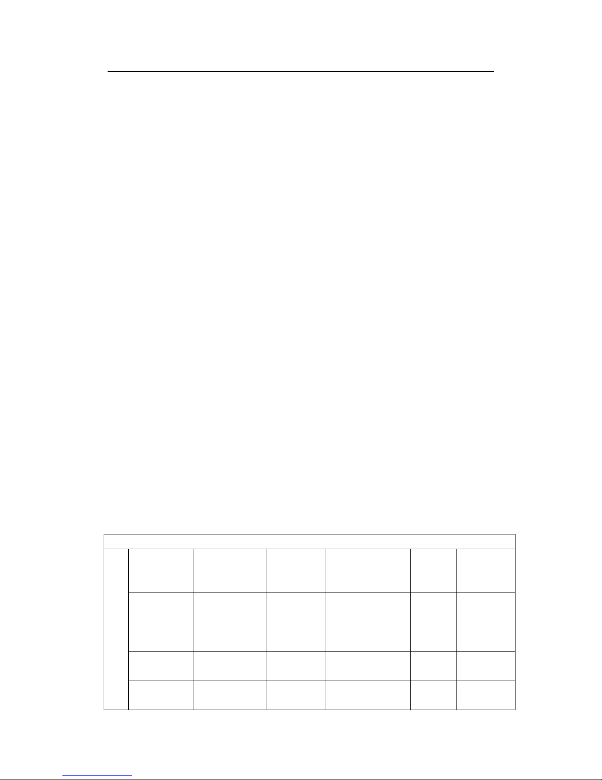
module type Cell type Cell
quantity module dimension
A*B*C(mm)
Install hole dimension
E*F(mm)
Cable Length
(mm)
Profile cross-section size
H*C*I(mm)
CLS-170P Multi 6*8 1335*990*50 1055*6.5
1000
12*50*32
CLS-190P Multi 6*9 1494*996*50 1214*6.5 12*50*32
CLS-230P Multi 6*10 1650*990*50 1020*6.5 12*50*32
CLS-270P Multi 6*12 1968*996*50 1688*6.5 12*50*32
CLS-170M Mono 6*12 1580*808*50 1300*6.5 12*50*35

Clamp fitting (portrait orientation): Use a certain number of clamps to fix the modules on the mounting rail.
The module clamps should not come into contact with the front glass and must not deform the frame. Be
sure to avoid shadowing effects from the module clamps. The module frame is not to be modified under
any circumstances. When choosing this type of clamp-mounting method, please be sure to use at least four
clamps on each module, two clamps should be attached on the long sides of the module. Depending on the
local wind and snow loads, additional clamps may be required to ensure the module can bear the load. The
applied torque should be about 8 Newton-meters. Please find detailed mounting information in the below
illustration
Table of contents
Popular Solar Panel manuals by other brands


Solarbayer
Solarbayer NANOSOL 135 Product information

Korax Solar
Korax Solar KS-90 installation guide

Yingli Solar
Yingli Solar YGE 245 Series Installation and user manual

AEROCOMPACT
AEROCOMPACT CompactFLAT SN10 Assembly instructions

Jackery
Jackery SolarSaga 100 user guide

Curtech
Curtech CT-K35 user manual