-2-
1Overview
In communication interface of LE5000 there are 4 types viz. RS-422A, RS-485, USB, Ethernet
available and are used for communicating with the personal computer (Hereafter referred to as PC).
PC can receive measurement data from LE5000, various parameters can be set and operation
commands can be executed.
Connection count of LE5000 is 1 USB and maximum 31 RS-422A/485.
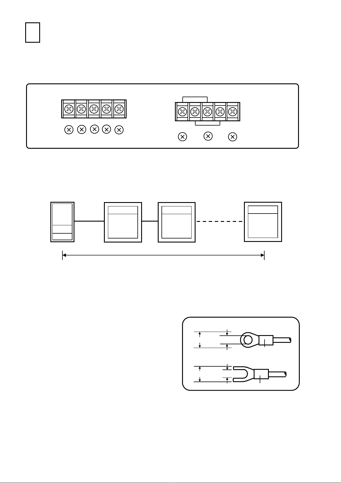
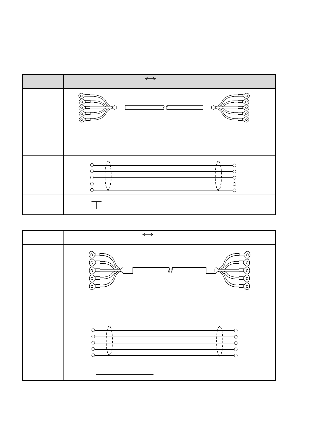
1.1 RS-422A/485 communication interface
RS-422A/485 communication interface can communicate by connecting in series multiple (maximum
31) LE5000 series machines through the signal that conforms to RS-422A/485.
Although the number of PCs having RS-422A/485is less, it can be easily connected by using
RS-232C RS-422A/485 signal converter, as it is a serial communication.
As this company also has line converters for RS-232C RS-422A/485 signal conversion, you can
place an order for them.
The difference between RS-422A and RS-485 is that, the former uses 4 signal lines whereas the later
uses 2 signal lines only.
1.2 Communication protocol
LE5000 series uses MODBUS protocol (MODBUS is a registered trademark of SCHNEIDER Company)
as communication protocol
MODBUS protocol has 2 modes viz. RTU mode and ASCII mode and they can be toggled using key
settings. MODBUS protocol has operation function and, settings and send function of measurement
data.
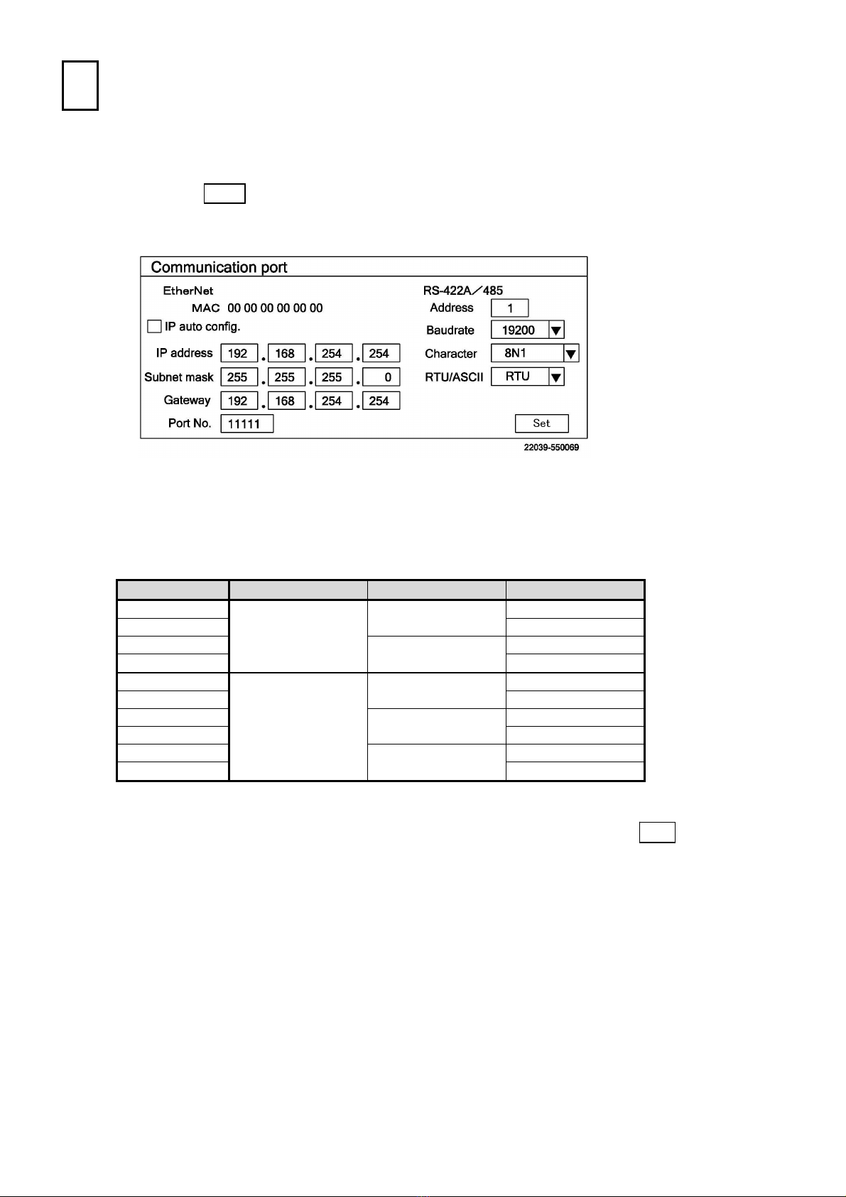
2Communication specifications
・Asynchronous method
・Half duplex communication method (Polling selecting method)
・Protocol: MODBUS protocol/usual protocol (Compatible with LE1000)
・Transmission speed:19200, 9600, 4800, 2400, 1200 bps switching possible (differs depending on
the protocol)
・Start bit:1 bit
・Data length: 7 bits/8 bits switching is possible
・Parity bit: Even (even parity)/Odd (odd parity)/Non (No parity) switching is possible
・Stop bit: 1 bit/2 bits switching over is possible
・Transmission code: Binary/ASCII (Differs depending on the protocol)
・Error check: Differs depending on the protocol
・External instrument priority communication method
・Data transmission procedure: No procedure
・Usage signal name: Send and receive data only (Without using control signal)