Chino AL3000 SERIES User manual

INST.No.INE-270J
AL3000 SERIES
(MULTI-POINT TYPE)
HYBRID RECORDER


0-1
PREFACE Requests and notices
Thank you for your purchase of AL 3000 series hybrid recorder (multi-point type) having a 100mm
recording width. Please read this instruction manual without fail for using this instrument correctly and
safely and also preventing troubles in advance.
Separate Instruction Manuals
This instruction manual describes the operation of the options consisting of ○
1alarm output, remote
contacts and ○
2printing format, high-speed trace printing as well as the operation of standard
specifications. When the instrument is provided with the communications interface (option), the instruction
manual for communications interface is attached as a separate manual. For other options, their instruction
manuals are attached respectively. Please read these instruction manuals together with this manual.
1. Request to designers, instrument controllers, and sale agents
Deliver this instruction manual to the operator of this instrument without fail.
2. Request to the operator of this instrument
This instruction manual is necessary for maintenance, too. Keep this manual with due care until the
instrument is discarded.
Notices
1. No part of this manual can be reproduced in any form, without permission.
2. For the contents of this manual, alteration is reserved without notice in the future.
3. This manual has been prepared by making assurance doubly sure about its contents. However, if any
question arises or if any error, an omission, or other deficiencies were found, please inform your nearest
CHINO's sales agent of them.
4. You are requested to understand that CHINO is not responsible for any operation results.

0-2
CONTENTS
Read the Following Instructions Without Fail
PREFACE / Requests and notices....................................................................................................................0-1
For safe use ........................................................................................................................................................0-5
Warnings..............................................................................................................................................................0-6
Major features and functions ............................................................................................................................0-7
Introduction
1. General.............................................................................................................................................................1-1
1.1 Model check and information..................................................................................................................1-1
1.2 Attachments and consumable parts ......................................................................................................1-2
Preparation
2. Installation ......................................................................................................................................................2-1
2.1 Mounting place and external dimensions.............................................................................................2-1
2.2 Mounting method to panel ................................................................................................................. 2-2
3. Names of component parts............................................................................................................................3-1
3.1 Front panel ...........................................................................................................................................3-1
3.2 Display board ............................................................................................................................................3-2
4. Connections .....................................................................................................................................................4-1
4.1 Terminal board diagram .....................................................................................................................4-1
4.2 Cautions on connections .....................................................................................................................4-2
4.3 Power and protective conductor terminals ......................................................................................4-3
4.4 Measuring input terminals ................................................................................................................4-4
4.5 Alarm output terminals (option) ......................................................................................................4-5
4.6 Remote contacts terminals (option) ................................................................................................. 4-7
4.7 Communications terminals ...............................................................................................................4-8
5. Installation ......................................................................................................................................................5-1
5.1 Chart loading.............................................................................................................................................5-1
5.2 Cassette ribbon installation ....................................................................................................................5-3
Basic Operation
6. Basic operation................................................................................................................................................6-1
6.1 Turning on and off the power supply and operation............................................................................6-1
6.2 Turning on and off the printing operation.............................................................................................6-2
6.3 Fast feed of chart/time line......................................................................................................................6-3
6.4 Selection of operation screens .................................................................................................................6-4

0-3
Programming
7. Programming procedure................................................................................................................................7-1
7.1 Necessity of programming and parameters/functions ........................................................................7-1
7.2 Default parameters/functions and programming ranges ...................................................................7-2
7.3 Programming keys and key operations.................................................................................................7-5
7.4 Programming procedures........................................................................................................................7-7
7.5 Programming error and remedial measures........................................................................................7-8
8. Basic programming (See Caution) ...............................................................................................................8-1
8.1 Parameters to be programmed before operation .................................................................................8-1
8.2 Ranges/printing ranges............................................................................................................................8-2
8.3 °C/°F operation selection..........................................................................................................................8-5
8.4 Chart speed................................................................................................................................................8-6
Operations and Functions
9. Printings ..........................................................................................................................................................9-1
9.1 Printings ....................................................................................................................................................9-1
9.2 Digital data printing.................................................................................................................................9-2
9.3 List printing...............................................................................................................................................9-3
9.4 Programming printing formats ..............................................................................................................9-4
10. Operations .....................................................................................................................................................10-1
10.1 Fixed-time printing intervals................................................................................................................10-1
10.2 Restrictions of printings.........................................................................................................................10-2
10.3 Operations at abnormal inputs ............................................................................................................10-3
10.4 Alarm display and printings .................................................................................................................10-4
Other Programmable Parameters/Functions
11. Other programmable parameters/functions.............................................................................................11-1
11.1 List of other programmable parameters/functions............................................................................11-1
11.2 Scale..........................................................................................................................................................11-2
11.3 Skip (channel deletion) function...........................................................................................................11-4
11.4 Subtract printing function.....................................................................................................................11-6
11.5 Programming alarms.............................................................................................................................11-8
11.6 Programming alarm dead band ...........................................................................................................11-11
11.7 Periodic data printing function.............................................................................................................11-12
11.8 Time ..........................................................................................................................................................11-13
11.9 Engineering units ...................................................................................................................................11-14
11.10 Tags.........................................................................................................................................................11-16
11.11 Burnout function...................................................................................................................................11-18
11.12 Passcode/key lock..................................................................................................................................11-19
11.13 Coping function.....................................................................................................................................11-22

0-4
Options
12. Alarm output.................................................................................................................................................12-1
13. Remote Contacts...........................................................................................................................................13-1
13.1 Remote contacts function .................................................................................................................13-1
13.2 Programming 3 chart speeds................................................................................................................13-2
14. Printing format .............................................................................................................................................14-1
14.1 Programming automatic range-shift printing....................................................................................14-1
14.2 Programming compressed and expanded printing ...........................................................................14-3
14.3 Programming zone printing..................................................................................................................14-5
15. Other options.................................................................................................................................................15-1
15.1 High-speed trace printing......................................................................................................................15-1
15.2 Shunt resistors for current input .........................................................................................................15-2
15.3 Mathematical function and totaliser ...................................................................................................15-3
Maintenance Functions
16. Adjustments ..................................................................................................................................................16-1
16.1 Adjustment of measuring values..........................................................................................................16-1
16.2 Shift programming of measuring values ............................................................................................16-4
16.3 Adjustment of trace printing position..................................................................................................16-5
17. Hardware checks..........................................................................................................................................17-1
17.1 ROM version check.................................................................................................................................17-1
17.2 Printer test...............................................................................................................................................17-2
17.3 Display test..............................................................................................................................................17-3
17.4 Alarm output check (option)..................................................................................................................17-4
17.5 Remote contacts input check (option)..................................................................................................17-5
18. Programming initialize................................................................................................................................18-1
Maintenance
19. Maintenance/Troubleshooting ....................................................................................................................19-1
19.1 Routine inspection..................................................................................................................................19-1
19.2 Lubrication and cleaning .................................................................................................................19-2
19.3 Measuring values check ...................................................................................................................19-3
19.4 Troubleshooting .................................................................................................................................19-5
19.5 Recommended parts replacement intervals .................................................................................. 19-7
Remarks
20. Specifications.................................................................................................................................................20-1
Theitemsmarkedwith intitlescontain and .
Read these items without fail.
Caution
Warning

0-5
FOR SAFE USE
1. Preconditions for Use
This instrument is designed for mounting on an indoor instrumentation panel for use. ( except for portable
type )
International safety standards …….Out of those having an alarm output (option), the mechanical relay 'c'
contact output specifications only does not conform.
・IEC standard : Conforms to safety class I (with PROTECTIVE CONDUCTOR TERMINAL) and
IEC1010-1 (OVERVOLTAGE CATEGORYⅡ, POLLUTION DEGREE 2)
Conforms to the enclosure protective degree IEC529 (IP54) (Front part).
・CE marking (EC Directive):
EMC : Conforms to EN55011 group 1 Class A, EN50082-2 (Industrial environment)
Safety : Conforms to EN61010-1 +A2
・UL standard : UL3111-1 approved
・CSA standard (C-UL) : CSA C22.2 No. 1010 Approved
2. Labels Employed
The following labels are used for safe use.
Label Name Meaning
Alert symbol mark Indicates the location which should refer to the manual in order
to prevent an electric shock and injury.
Protective conductor
terminal
Terminal connected to the protective conductor of power supply
equipment for preventing an electric shock accident.
3. Symbols in This Manual
The cautions to be observed for preventing the damage of this instrument and unexpected accidents are
sorted by the following symbols according to their importance degrees for enabling operators to use this
instrument safely.
Symbols Ranges of cautions
Thissymbolisdescribedinthetitles(items)where or
isexplained.
This symbol describes the cautions for avoiding the possibilities when the user is
in danger of causing serious injuries or death due to an electric shock accident or
other accidents.
This symbol describes the cautions for avoiding the possibilities when the user is
in a danger of causing slight injuries or this instrument or peripheral units may
be damaged.
This symbol shows a caution when this instrument does not function as spedified
or when such a possibility exists.
This reference serves as a supplement for handling and operation, and it may be
convenient for users.
Reference
Warning
Caution
Remarks
Warning
Caution

0-6
WARNINGS
This paragraph covers important warning for safety to be observed before reading the instructions.
Fully understand the following warnings before reading this manual.
These warnings are important for preventing the danger to human bodies as well as accidents.
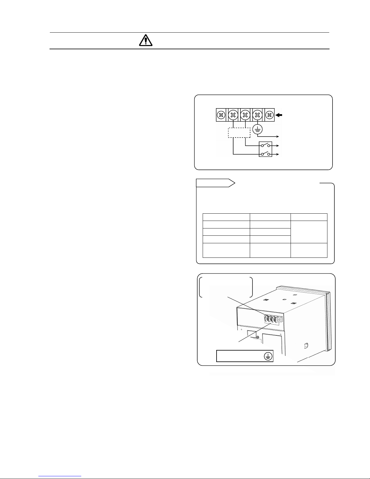
1. Switch and overcurrent
protective device
This instrument is not provided with any power
switch and any replaceable overcurrent protective
device. Mount a switch and an overcurrent
protective device (breaker, circuit protector or the
like) for the power supply within 3m where the
operator can reach them handily. Use these switch
and overcurrent protective device conforming to
IEC947-1 and IEC947-3.
2. Connect the instrument to
the ground without fail.
Connect the protective conductor terminals of this
instrument to the protective conductor of the
power supply equipment. Don't disconnect them
during use for the purpose of preventing an
electric shock accident.
3. Before turning on the power
supply first
Make sure that the feed voltage is within the
range indicated on the power label for safety
before turning on the external power switch.
4. Don't repair or modify the
instrument.
Don't repair or modify the instrument by replacing
parts by any persons other than servicemen
approved by our company, otherwise the
instrument may be damaged or the instrument
does not function normally, and also, accidents like
an electric shock accident may occur.
The internal unit and case are provided with
electric circuits and moving parts.
Don't put your hands, etc. into them, otherwise an
electric shock accident or injuries may result.
5. Use the instrument according to the instruction manual.
Use the instrument correctly and safely according to this instruction manual.
You should understand that we are not responsible for any injuries, damage, lost profits, and any other
demands which may be caused by wrong uses.
6. Stop feeding power supply, if an abnormal symptom occurs.
If abnormal odor, noises, or smoke occurs, or if the instrument is hot to such an extent as it cannot touch
by hand, a dangerous trouble may occur. Turn off the power supply at once, and inform CHINO's sales
agent of it.
Overcurrent
protective
device
(250V 3A)
Switch
Feed power
To protective
conductor of power
supply equipment
Power terminals
and protective
conductor terminal
LN
Power terminals
Protective
conductor terminal
100-240V AC
50/60Hz 45VA MAX
Power label
The following fuse is mounted in the power
supply unit of this instrument for safety use.
However, this fuse is not replaceable.
Manufacturer Model Ratings
SCHURTER SPT001.2508
LITTEL FUSE 21502.5
WICKMANN 19181
250V AC
2.5A
LITTEL FUSE 215002P 250V AC
2A
Fuse in power supply unit
Reference

0-7
MAJOR FEATURES AND FUNCTIONS
This instrument can record temperature and other various industrial variables on a 100mm chart in 6
channels.
○
1Trace printing by dots
○
2Digital printing to print measured values and other data
1. Features
Major features are shown below.
・Universal input. A range can optionally be selected every channel out of 10 DC voltage ranges, 36
thermocouple ranges, and 11 resistance thermometer ranges.
・Universal power supply. The working voltage range is 100 to 24OVAC, 50/60Hz.
・Conforms to international safety standards. Conforms to CE marking or approved and UL and CSA
(C-UL) approved.
・The basic operation is done after programming range numbers and trace printing range.
・All operations can be done on the front keyboard without any need of drawing out the internal unit.
The internal unit cannot be drawn out.
2. Functions
Major functions are shown below.
Display functions Printing functions
・Simultaneous display of measured values in 6
channels
・100mm bargraph display (one channel)
・Three kinds of status are displayed.
・Operation screens selectable
・A measured value flickers when alarm is on.
(Note)
・Trace printing of 6 channels by dots
・Fixed time printing (time line, time, scale,
engineering unit, tag)
・Periodic data printing (Measured values are
digitally printed at preset intervals.)
・Digital data printing (Digital printing of
measured values on demand)
・Alarm printing
(Note)
Note: Programming of alarms is necessary. Alarm output is only available by adding an option of
[Alarm output].

1-1
1. GENERAL
1.1 Model Check and Information
1. Model check
A label showing the model is stuck to the
upper face of the case as well as the
bottom face of the internal unit after
drawing out the chart cassette.
MODEL AL3765-N00
No 987A001
2. Information
1) Attached chart
Chart No. EM-001 (0 to 100) will be delivered. Charts
conforming to various scales are also available as shown
below.
Scale Chart No. Scale* Chart No.
0 to 50 EM-003 0 to 50°C EL-05014
0 to 100 EM-001 0 to 100°C EL-05052
0 to 150 EM-A001 0 to 150°C EL-05034
0 to 200 EM-A002 0 to 200°C EL-05047
0 to 300 EM-A003 0 to 300°C EL-05010
*Each scale is linear. It is usable irrespective of the types of
thermocouples and resistance thermometers.
2) Printing restrictions
1.None of digital printing is done at a faster chart speed
than 251 (mm/h).
2.Trace printing is executed at fixed intervals. However,
these executed intervals may be more or less longer if they
overlap with digital printing.
3.Digital printing is executed by 1-pin dots and a character
is composed of 7 lines. If power supply is turned off
halfway, a complete character cannot be formed.
■Models
AL 3 7 6 5 – N 0 0
Input signal
[7] Fixed: Universal input
(DC voltage, thermocouple, Resistance thermometer)
No. of Input points (A: option)
6: 6-point (Measuring interval 5 sec)
A: 6-point (Measuring interval 1 sec)
Display specifications
[5] Fixed: Standard (Simultaneous display of 6 measured values)
Communications Interface (option)
N: None A: RS-422A S: RS-485 R: RS-232C E:Ethernet
Alarm output and remote contacts (option)
0: None 1: 6 MOS relay outputs + remote contacts
2: 6 mechanical relay 'c' contact outputs + remote contacts(*)
A: 6 mechanical relay a contact outputs + remote contacts
Others (option)
0: None 1: Printing format + high-speed trace printing
Model
Serial No.
*Not conforming to
CE-marking, UL and CSA.
Label 1
Label 2
See 5.1.
Drawing out the chart cassette
Reference

1-2
1.2 Attachments and Consumable Parts
1. Attachments check
The following attachments are contained. Check if these attachments are delivered normally.
Part names Q’ty Remarks
1. Chart 1 pad Chart No. EM001
2. Mounting bracket 2 pcs. Used for mounting the instrument to a panel.
3. Cassette ribbon 1 Pc. 6-color ink ribbon for analog and digital printing
4. Channel indicating card 1 sheet Inserted inside the door
5. Lubricating oil 1 bottle For lubricating the main shaft of printer
6. Terminal screw 5 pcs. M3.5 screws Auxiliary screws for input and alarm terminals
1 pad INE-270 (for main unit)
7. Instruction manual (1 pad) INE-272 (for communications interface)
Attached to the instrument with communications interface.
2. Ordering of consumables
Chart and cassette ribbon are consumables. For ordering them, please specify them, referring to the
following table.
Name Article name and specifications for ordering Handling unit
Chart Chart No. (Example EM-001)* 1 case (containing 15 pads)
Cassette ribbon 6-color cassette ribbon (For AL: No. 84-0044) 1 piece
* Please indicate it if a 16m-length chart is requested.
5. Lubricating oil
1. Char
t
4. Channel indicatin
g
card
3. Cassette ribbon
2. Mountin
g
bracke
t
6. Terminal scre
w

2-1
2.INSTALLATION
2.1 Mounting Place and External Dimensions
Mount the instrument at the following place so as not to affect the measuring accuracy and recording
operation unfavorably.
1. Industrial environment
Select a place being separated from electric field and magnetic field generation sources and also free of
mechanical vibrations and shocks.
・OVERVOLTAGE CATEGORY……Ⅱ
・POLLUTION DEGREE……………2
・Altitude……………Lower than 2000m
・Working place…….Indoors
2. Ambient temperature and humidity
Don't expose the instrument to the direct sunlight. Don't enclose the instrument to prevent a temperature
rise.
・Mount the instrument at a stable place where the ambient temperature is about 23°C and the relative
humidity is about 50% RH.
・Mount the instrument at a place free of being exposed to hot blast (higher than 70°C ) for preventing its
door from being deformed.
・Mount the instrument at a place being free of a heat source near its terminals for the purpose of reducing
measuring errors.
3. Atmosphere
・Don't mount the instrument at an inflammable gas atmosphere for securing safety.
・Don't mount the instrument at any place where dust, smoke, vapor, and other substance exist.
4. Mounting angle and display view angle
1) Mounting angle
・Lateral tilting………….0° to 10°
・Longitudinal tilting…...Forward tilting: 0 °
Backward tilting : 0°to 30°
2)Display view angle
・View angle…….-10°to +30°based on horizontal
5. External dimensions
The following figure shows the external dimensions of the instrument together with its mounting brackets.
Display
A
pprox 1
0
°
A
pprox 3
0
°
V
iew angle
18 63
144 24 237*
14
4
161
13
7
×137
*When
mechanical
relay 'a'
contact alarm
output is 243.

2-2
2.2 Mounting Method to Panel
1. Panel cutout size
Standard product Alumimum die-cast door (option)
Unit: mm
Single unit mounting…..
Same as in the standard product
Lateral tight mounting instrumentation
n : Number of units
2. Mounting method
1) Insert the instrument into the panel cutout
from the front of the panel.
2) Fix the instrument to the panel by the mounting
brackets (Tightening torque 1.0 N.m ). Fix the
mounting brackets at 2 positions on the upper and
lower faces.
(144×n)-6
+2
0
138
+1
0
138
+1
0
200
200
138
+1
0
This instrument is designed to be mounted on a panel.
Use a panel made of a steel plate of 2 mm to 6 mm in thickness.
Mount the instrument on a panel
W
arning
Panel thickness
(
2 to 6 mm
)
Mounting bracket
Mounting bracket

3-1
3.NAMES OF COMPONENT PARTS
3.1 Front Panel
All operations of this instrument including the installation of ribbon cassette can be done from the front.
1) Display board
For installing the cassette ribbon, swing open the display board to the left. For details of the display board,
refer to the next page.
2) Chart cassette
Load the chart to the chart cassette.
3) Keyboard
For operation and programming, press necessary keys.
Operation keys
Three operation screens are switched by pressing this key.
→Turns printing ON or OFF.
Feeds the chart at a speed of about 10(mm/sec) when this key is being pressed.
→Prints measured value digitally at the time when this key is pressed (on demand).
+ → Prints the programmed parameters as a list.
Programming keys
Press various keys other than described above.
Door
Display board
Chart cassette
Keyboard
The front face of the door is made of glass. Don't give any shock to the glass face nor give any strong
force to the frame for preventing an injury due to the breakage.
How to handle the door
Caution

3-2
3.2 Display Board
1) Channel No.
Channel number of [bargraph]. Display depends upon the operation screens.
[Multi-point sequential bargraph display] [One-point continuous bargraph display] <Digital printing in progress>
2) Measured value
Measured values of each channel are displayed simultaneously. The upper part of the [clock display and
others] screen indicates channel numbers of alarm-on and chart speed, while the lower part indicates time
(year/month, day/time).
3) Status
ALARM (red)……………….Illuminates when alarm is ON.
RECORD ON (green)……...Illuminates when printing is ON.
KEY LOCK (blue)……….…Illuminates on key lock status.
4) Bargraph
Displays the trace printing position of the channel being indicated in [Channel No.] with the resolution of 2%.
This display is interrupted during digital printing.
1) Channel No.
2) Measured
value (clock)
3) Status
4) Bargraph
The operation screen is switched in the order of [Measured value display/multi-point sequential
bargraph display]- [Measured value display/one-point continuous bargraph display] - [Clock display
and others/onepoint continuous bargraph display], each time [Display] key is pressed once.
See paragraph 6.4.
Operation screen selection
Reference

4-1
4. CONNECTIONS
4.1 Terminal Board Diagram
The terminal board shown in the following figure is for the instrument with options ( alarm output + remote
contacts and communications interface ) are mounted.
The alert symbol mark ( ) is mounted at a place where one may receive an electric shock if one
should touch. (See the following table) Read paragraphs describing the connections of individual
terminals.
Name of terminals Power terminals Measuring input terminals Alarm output terminals
Mounting place of
label
Lower left of power
terminals Upper left of terminal cover Upper left of terminal
cover
The input terminal block and alarm terminal block* are removable for easy connections.
*The terminals for the remote contacts are included.
1) Each terminal block can be removed by removing
two mounting screws.
2) Each terminal block is connected to the
instrument by a connector.
For mounting or dismounting the terminal
block, turn off the external power switch
for the purpose of preventing the electric
circuits from being damaged.
If the input terminal block is replaced with a new one, the calibration of thermocouple inputs
becomes incorrect.
Communications terminals
*
(
M3.5
)
(
o
p
tion
)
Alarm output terminals
(M3.5)(option)
Remote contacts terminals
(M3.5) (option)
Measuring input
terminals (M3.5)
Power/protective conductor
terminals (M4) * For the connections of
communications terminals, refer to
the separate [instruction manual for
communications interface].
(Caution)
Alarm output terminals
illustrated are MOS relay
output and mechanical relay
'a' contact outputs. Mechanical
relay 'c' contact outputs (The
lnternational safety standards
do not conform) differ the
terminal configuration.
TC,mV
(
+
)
, RTD
(
A
)
terminals
TC,mV (-) , RTD (B) terminals
RTD (B) terminals
Normall
y
open
(
N.O
)
terminals
Common
(
COM
)
terminals
Alert symbol marks ( ) and places
Warning
Mounting screw
Input terminal
bloc
k
Input terminal block and alarm terminal block are removable
Turn off the power supply in advance.
Caution
Reference
Re
p
lacement of terminal bloc
k
Remarks

4-2
More than 3.7
Less than
8
Less than
8
More than 3.7
More than 4.3
Less than 8.
5
t : 0.8
(with an insulation sleeve)
t : 0.8 (with an iosulation sleeve) t : 0.8 (with an insulation sleeve)
Use O-chi
p
(
left side
)
4.2 Cautions on Connections
Observe the following cautions during connections for securing safety and reliability.
1.Feed source power supply
Use a single-phase power supply having a
stable voltage without any waveform distortion
for the purpose of preventing wrong operations.
Add a switch and an overcurrent protective
device (3A) to the feed source power supply
for preventing an electric shock accident
during connection work. This instrument is
not provided with any replaceable
overcurrent protective device.
Turn off the feed source power supply in
advance without fail for preventing an
electric shock accident when the power
supply and input/output terminals are
connected.
2. Separate input/output
connections from a strong
power circuit
Don’t place the input/output cables to be close to
or in parallel with any strong power circuits
including power line. Separate them more than 50
cm from strong power circuits when they are
placed to be close to or in parallel with strong
power circuits.
3. Separate the thermocouple input
terminals from a heat source
For thermocouple inputs, separate the input
terminals from a heat source (a heating body) for a
purpose of reducing a reference junction
compensation error. Don't expose the input terminals
to the radiation of direct sunlight, etc.
4. Separate all connection
cables from noise sources
Separate all connection cables to the instrument from
a noise source as far as possible, otherwise an
unexpected trouble may occur. Take a remedial
measure if the cables cannot be separated from a
noise source due to unavoidable circumstances.
Major noise sources Remedial measures
Electromagnetic switch,
power line having
waveform distortion,
inverter, thyristor regulator
Insert noise filters
between power
terminals and
input/output terminals.
A CR filter is often used.
5.Use crimp style terminals
1) Mount crimp style terminals as connection cables'
termination for preventing the looseness or
disconnection of terminals and a short-circuit failure
between terminals.
2 )For crimp style terminals, use an insulation sleeve for
preventing an electric shock accident.
6. Unused terminals
Don't use any unused terminals for relaying, otherwise
electric circuits may be damaged.
Term ina l
name
Screw
diameter
Tightening
torque Termination (unit: mm)
Power and
protective
conductor
terminals
M4 1.2 N・m
Terminals
other than
described
above
M3.5 0.8 N・m
Addition of a switch and an
over current protective device
Warning
Turn off the feed source power
supply before starting connections
Warning
Treat connected cables securely so as not to allow them to be hooked by a person or a substance,
otherwise the connections may be disconnected or cut to cause an electric shock accident or other
Treat connected cables properly
Warning
Kinds of terminals and terminarion
Reference

4-3
4.3 Power and Protective Conductor Terminals
1. Power terminals and protective
conductor terminal
2. Connection of power terminals
For the connections to power terminals, use a 600V vinyl
insulated cable (IEC 227-3 Note), with the crimp style
terminals and an insulation sleeve.
Note: Use the cords approved by the following standards.
1) IEC 227-3 or 2) ANSI/UL817
3) CSA C22.2 No.21/No.49
3. Connection of protective
conductor terminal
Connect this terminal to the protective conductor of the
power supply equipment without fail. For this connection,
use a cable with a crimp style terminal and an insulation
sleeve.
Grounding wire : A copper wire having a wire diameter of
larger than 2mm2
Turn off the feed source power supply without fail
before connecting the power terminals and protective
conductor terminal for the purpose of preventing an
electric shock accident.
Turn off the feed source power supply
Warning
The power voltage of this instrument is indicated
beside the power terminals. Don't apply any voltage
other than indicated, otherwise a trouble occurs or
malfunction results. If noises are mixed into the power
supply, take a remedial measure, such as the addition
of a noise cut transformer
,
etc.
Be careful with the power voltage and noises.
Caution
A voltage of 100 to 240V AC is applied to the power
terminals after connections. Mount the power
terminal cover without fail after connections for the
purpose of preventing an electric shock accident.
mark at power terminals
Warning
10
0
-240V A
C
50/60Hz 45VA MAX
L N
Power terminals
Protective conductor terminal
Power supply
(voltage, frequency, power consumption)
LN
Mount the terminal
cover after
connections.
(See the following
figure)
A copper wire having a
diameter of larger than
2mm2 (green/yellow)
600V vinyl insulated cable
Power supply
Connect to the protective
conductor of the power supply
equipment without fail.
This indication conforms to the CSA
standard, Canada. The live side of the
single-phase AC power supply is
indicated as L, and the neutral side is
indicated as N. Observe the L.N
connections for obtaining satisfactory
performance.
L.N indication of power terminals
Remarks

4-4
4.4 Measuring Input Terminals
1. Measuring input terminals
Turn off the feed power source for preventing an
electric shock accident.
1) Measuring input terminals are provided at the
lower part of the terminal board.
2) For the connections to input terminals, use
cables with crimp style terminals and an
insulation sleeve.
2. Connections of DC voltage
(current) input
Use a twisted cable for instrumentation as the
input cable for the purpose of suppressing noises.
For current inputs, mount shunt resistors (par.
15.2) to the channels to be measured before
connections.
3. Connections of
thermocouple inputs
Use a thermocouple wire (or extension wire) to
the input terminals of this instrument without
fail. If a copper wire is used halfway, a noticeable
measuring error occurs. Don't use a pair of
thermocouple wires in parallel with other
instruments (controller, etc.) otherwise a trouble
may occur. By influence of signal source
resistance or the like, other instruments
(controllers, etc.) may have indication error.
4. Connections of resistance
thermometer inputs
For the input wire, use a 3-core cable where each
lead wire has an equal resistance value. Don't use
one resistance thermometer in parallel with other
instruments (controller, etc.).
A high voltage may be applied to the measuring input terminals due to common mode noises. The
allowable noise value is lower than 3OVAC or lower than 6OVDC. Make sure that the noises are
lower than the allowable values. Mount the terminal cover after connections for the purpose of
preventing an electric shock accident and protecting the input wires. In case of thermocouple inputs,
an error of the reference junction compensation can be reduced by the terminal cover.
Input type Allowable input voltage
Voltage
Thermocouple input
±10VDC (Range of
less than ±2V)
±60VDC (Range of
more than ±5V)
Resistance
thermometer input ±6VDC
Allowable input voltage
Caution
Ter m in a l co ver
Mounting screw
Term ina l co ver
DC voltage (current) input
1 2 3 4 5 6
Twisted wire for
instrumentation
(+)
(-)
DC voltage input
3-core cable (each lead wire having an
equal diameter and an equal length)
Resistance thermometer
Note : Use a 3-core cable where each lead wire has an
equal resistance value (lower than 10Ω).
Resistance thermometer input
1 2 3 4 5 6
A
B
B
( ) mark of measuring input terminals
Warning
Thermocouple input 1 2 3 4 5 6
Red(+)
White(-)
Extension wire
Thermocouple

4-5
Alarm output terminals
COM
N.O
N.
C
4.5 Alarm Output Terminals
The following connections apply to the instrument with an alarm output function (option) only. There are
three kinds of alarm outputs available: (1) MOS relay 'c' contact output, (2) mechanical relay 'c' contact and
(3) mechanical relay 'a' contact output, which are shipped by the designated outputs. The mechanical relay 'c'
contact output does not conform to the international safety standards.
1. Alarm output terminals
The terminal arrangement depends upon the type of alarm output.
MOS relay and mechanical relay 'a' contact outputs Mechanical relay 'c' contact output
*The international safety standards do not conform.
2. Connections
Turn off the feed power source and buffer relay power supply before starting connections for the purpose of
preventing an electric shock accident.
(1) Connect cables to the load via a buffer relay.
(2) Mount a crimp style terminal with an insulation sleeve to the alarm output terminals before connections.
Example of MOS relay and mechanical relay 'a'
contact outputs Example of mechanical relay 'c' contact outputs
: Contact protective element
(It is recommended to mount this element
on the ‘a’ side)
: Contact protective element
(It is recommended to mount this element on the ‘a’ side)
*N.O terminal ----- Close relay contact when alarm is on.
N.C terminal ----- Open relay contact when alarm is on.
Connect a load of less than specified (See Remarks 1 and 2) to the alarm output terminals. A buffer relay
power supply is applied to the alarm output terminals after connections and an electric shock accident
occurs if you should touch these terminals. Mount a terminal cover without fail after connections.
An alarm output of this instrument may become defective due to wrong operation, failures, abnormal
inputs, or other troubles. Take a safety measure against an output failure before use as occasion
demands.
Alarm output terminals
N.O
COM
Load
Power supply
N.O
COM
a
b
This instrument Buffer relay
Load
Buffer relay
Power supply
N.O
COM
N.
C
a
b
This instrument
*
mark of alarm output terminals
Warning
Takeasafetymeasure
Caution
Other manuals for AL3000 SERIES
2
This manual suits for next models
1
Table of contents
Other Chino Recording Equipment manuals