Chinowing T31 User manual
www.chinowing.com
1
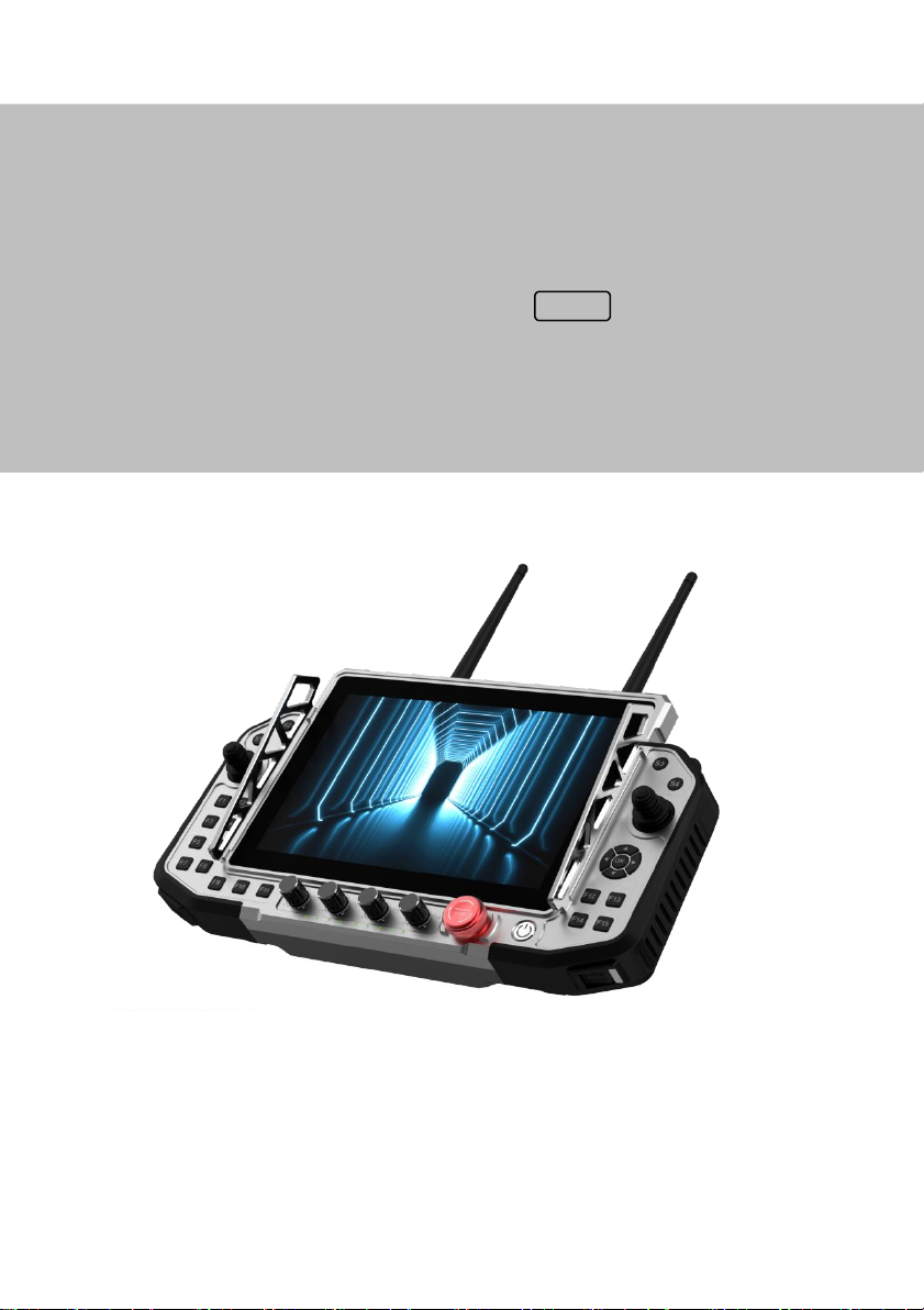
T31
Hand-held Ground Control Station
USER MANUAL V 1.0.1
data image transmission version V21
2022.09

www.chinowing.com
2
Content
Disclaimer ...........................................................................错误!未定义书签。
Product precautions .....................................................错误!未定义书签。
Installation Note ...............................................................................................5
Precautions for use......................................................................................6
Product introduction ................................................................................................. 7
Item list(V21) ..........................................................................................................7
Product instruction .............................................................................................. 8
T31 Main control part name.................................................................... 8
V21 Identification description ............................................................... 11
Remote control operation ................................................. 错误!未定义书签。
Remote control&Computer power-on and power off ...................13
Indicator Instruction of Remote Controller and Receiver错误!未定义书签。
Remote control Parameters setting software operation错误!未定义书签。
Assistant software description .............................................................. 15
Channel monitoring and calibration ......................................................16
Channel configuration........................................错误!未定义书签。
Fail-safe setting .................................................... 错误!未定义书签。
Channel hold .........................................................错误!未定义书签。
Key setting ............................................................. 错误!未定义书签。
Comprehensive settings..........................................................................25
Remote control charging ........................................................................30
V21data video link module operatio and use ............................................31
V21connection instruction ..................................................................... 31
Serial port use ............................................................................................ 31
V21 LAN port use...................................................................................... 33
V21 module configuration ......................................................................35
V21 digital video module specification .....................................................40

www.chinowing.com
3
T31 remote control port description ...................................................................... 41
Aviation plug connector output description错误!未定义书签。
Gamepad HID controller ................................... 错误!未定义书签。
Firmware upgrading operation steps...........................................................45
V21 Receiver wireless firmware upgrade ........................................... 48
Common questions...................................................... 错误!未定义书签。
Product specification ................................................... 错误!未定义书签。
Version update history ................................................ 错误!未定义书签。

www.chinowing.com
4
Disclaimer
Thank you for purchasing the T31 hand-held remote-control station.Here
referred as T31. Please use it in accordance with local radio control regulations
and read this statement carefully before using it. Once used, it shall be deemed to
endorse and accept all contents of this statement. Please strictly follow this
instruction to install and use the product. The supplier will not bear any legal
liability for any result or loss caused by improper use, installation, final assembly
or modification of the product.
Product precautions
1. T31 as ground terminal(ground unit)is matched with air terminal
(airborne)end to use together.
2.The ground terminal is with built-in 12v battery (3S lithium battery). The
airborne end needs external power input DC7.4-12V(2S-3S lithium battery).
Please power the system in strict accordance with specifications.
3.With improper operation, the aircraft may cause a certain degree of injury and
damage to human and the system, please be sure to pay attention to safety during
use.
4. In order to better serve customers, our R&D team has been upgrading and
optimizing the product. The software and firmware are being upgraded
frequently. There may be incompatibilities between different firmware versions
of ground terminal and airborne . So please check the version of software and

www.chinowing.com
5
firmware and pay attention to our website,ask the supplier for the latest
software firmware and technical support.
5.Basic software and firmware version example:<Parameter Setting
Software>:chinowing remote controller 1.3.0。Ground unit firmware:
TTx31_HW_V1.8__SW_1.0.8_BT_2.4。Airborne unit:V21RX-1.0.4。
6.The software, firmware, drivers and port conversion tools covered in this
manual will be updated from time to time on our website, so please visit our
website to download them, or contact us directly.
1) 7.If you encounter any problem that cannot be solved during installation or
use of the product, please contact us or visit our website:www.chinowing.comto
get help with.
Installation Note
1. Be sure to use the spare parts provided by our company.
2. Be sure to install the antennas before power-on to avoid damage to the circuit.
3.Try to make the receiver antenna without obstruction, and the end part of the
antenna is vertically downward without bending, so as to avoid shortening the
communication distance or even failing to communicate due to obstruction.

www.chinowing.com
6
4.Do not disassemble or refit without permission. If you encounter any problem
that cannot be solved during installation, please contact us directly or
Contact the agent.
5.During installation, keep proper distance between electronic devices to
minimize electromagnetic interference.
Precautions for use
1. Before use, please make sure that all connection wires are fastened reliably
and all components work normally.
2.Please open the <RC Configuration Software> and check whether the channels
are normal.
3.Please check the surrounding environment to ensure that there is no
interference from other devices, otherwise T31 data transmission performance
will be seriously affected.
4.Ensure that the antennas are free from obstacles and bends during use, and stay
away from large metal structural parts as far as possible to avoid communication
obstruction
5. Check the power of the remote control before use. If the <Parameter Setting
Software> shows that power is low, please charge the remote control timely. If
the remote control is turned off, the receiver has entered the state of out-of-
control protection. Stop using it when the battery is too low. Don't rely on the
device's low-power alarm, which is only a precaution and tells you when to
charge.Check the power of remote control every times before you use. It takes
about 3hs to be fully charged.
www.chinowing.com
7
Product Introduction
T31 is all-in-one hand-held GCS that integrates remote control, data transmission
module, video transmission module and industrial computer.
High integration, small size, easy operation,abundant physical channels
adjustable,double S-BUS output,35 physical channels.Each channel of T31 dual S-
BUS can be configured with 10 analog channels and 25 buttons,among which 5
groups of combination buttons and 2 groups of super combination buttons can be
freely mapped.When matched with D01G,CAN programmable custom protocol
can be configured.
T31works in 800MHz(806-826Mhz)、1.4GHZ(1427-1467Mhz、
2.4GHZ(2401.5-2481.5MHZ)frequency bands,and can provide stable data
transmission at a distance of 10km to 30km according to different versions and
environments.Widely used in industrial control field and data transmission aerial.
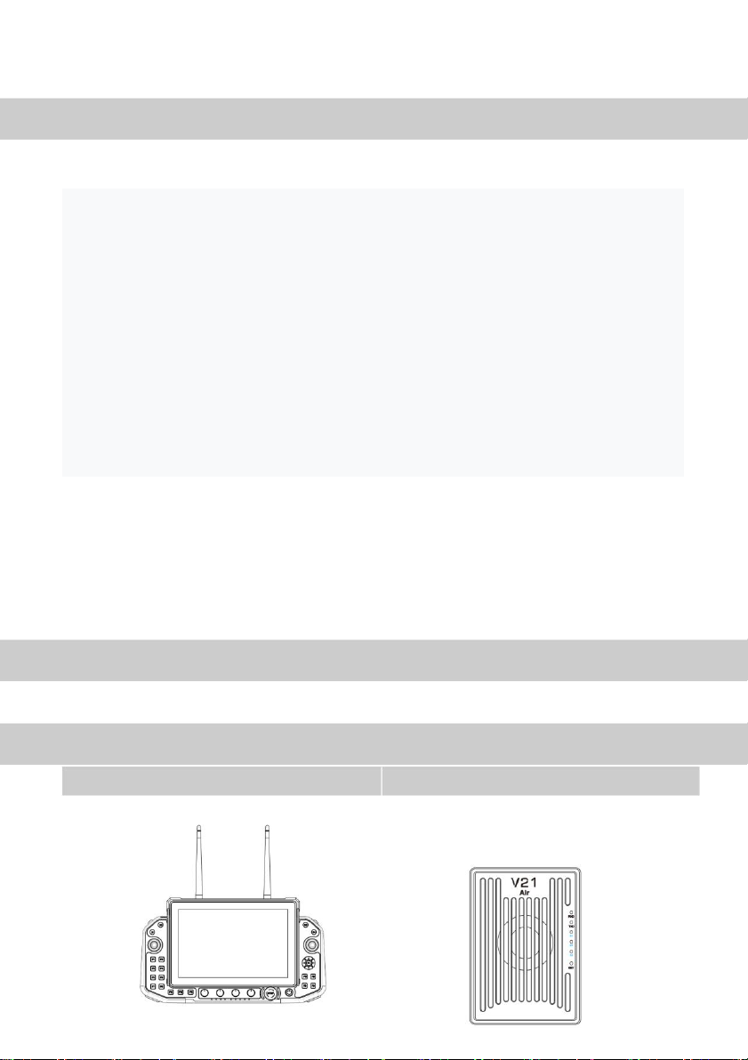
Item List (V21)
Main module
T31remote control
×1
V21receiver
x 1

www.chinowing.com
8
Accessories
Product Instruction
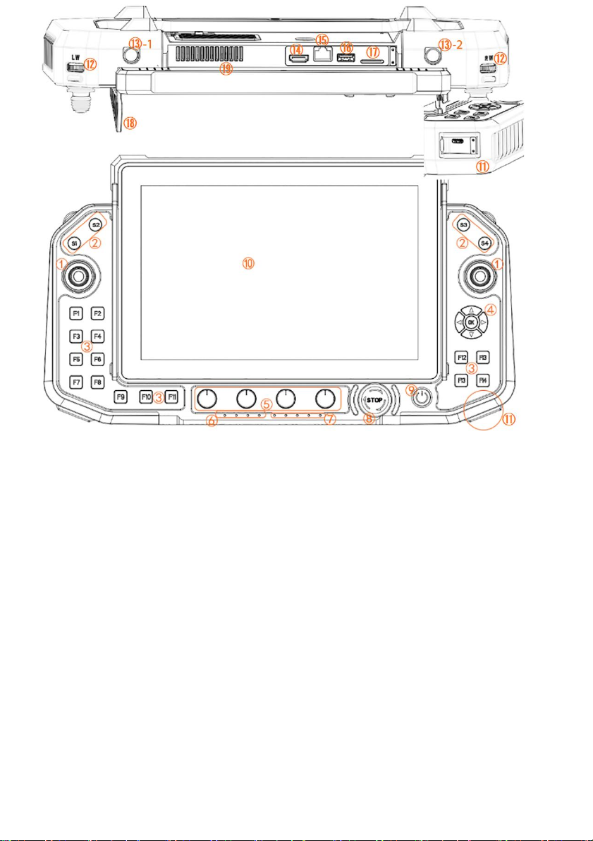
T31 main control part name
TNC 1430-1444Mhz Antenna×2
SMA
1430-1444Mhz Antenna×1
T31 transmit antenna
V21 receiver antenna
Charger×1
Network port-
to-4pin wire x1
Cables
65W fast charger*1
USB Type-c*1
Use for airborne
connecting with WAN
port equipment
1、Power connectorXT31 power cable * 1
2、SBUS GH 3pin *2
3、TTL signal line GH 4pin *2
www.chinowing.com
9
①Hall rocker
corresponding T1, T2, T3 and T4, used for flight control
②Custom Switch buttons
Corresponding S1-S4
③Custom independent buttons
Corresponding F1-F15
④Custom arrow buttons
Corresponding to front,back,left,right and confirm keys
⑤Custom four knobs
Corresponding R1-R4
⑥Battery indicator
For battery capacity and power-on indication
⑦Signal strength,transmitting and receiving indicator
Used for wireless module working status
⑧Custom emergency stop button
For emergency stop equipment
⑨Power button and indicator light
www.chinowing.com
10
Long press to power on,short press to display the battery
⑩Touch screen
Click on the screen
⑪usb type-charging port
Corresponding 5V/3A,9V/3A,12V/3A,15V/3A,20V/3.25A,20V/3.25A
65W(MAX)
⑫Pulsator(back to middle)
Corresponding LW,RW
⑬-1 aviation plug 6pin output ⑬-2 aviation plug 4pin output
TwoSBUS,and RS232(COM4) Reserved function
⑭HDMI interface
Output HDMI signal to HDMI display
⑮Network port
RJ45 and external wired network connection
⑯USB port
USB3.0 port
⑰4G card slot
Standard SIM can be used to surf the internet on mobile 4G network
⑱Protector rod ⑲Air outlet
For hanging straps and protection Ground station cooling vent,please do
not blcok the air outlet when using
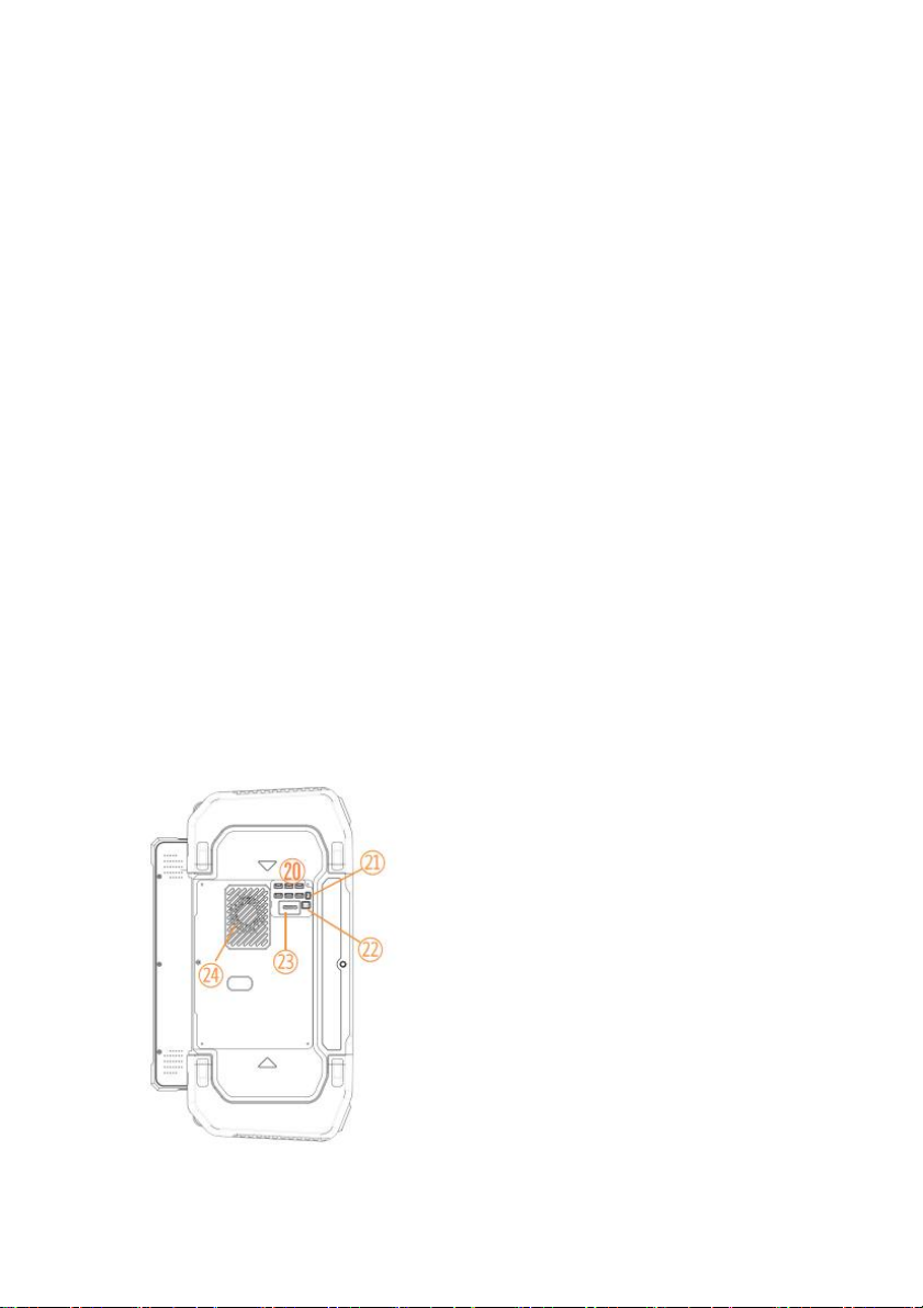
⑳GH4pin signal output interface
RS232*2,LAN*2,USB 3.0,DEBUG(debug interface)
For communicating with other third-party modules
㉑DC 5Voutput
For cooling fan power supply
㉒12V Battery voltage output
For V21 video transmission module power supply or for third-party
video transmission module power supply.
㉓V21 Image transmission signal line
It is used for image transmission and remote control
communication,such as using a third-party image
transmission,connect with D01G.
㉔Inlet
Computer CPU radiator air inlet,do not block it when using

www.chinowing.com
11
V21 identification description
Front view
1Data receiving indicator: light will flicker in the condition of data receiving.。
2Date transmitting indicator: light will flicker in the condition of data
transmitting.
3Signal strength indicator: S3 ON, signal is weak; S3 and S2 ON, signal is
moderate; S3, S2 and S1 ON, signal is strong.
㉕Main antenna
Itis used to transmit and receive signals.Be sure to
install the antenna when using it and start
using it. 用于发射和接收信号,使用时务必安装
好天线在开机使用
㉖Secondary antenna
For signal reception
www.chinowing.com
12
4SET key:used for firmware upgrading,serial port baud rate settings,RC fail
safe protection settings.
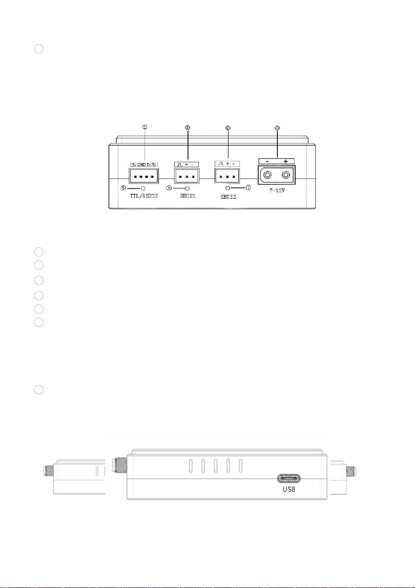
Side view
1TTL port: full duplex serial port
2S-BUS1 port:SBUS input(ground unit);SBUS output(airborne unit)
3S-BUS2 port:SBUS input(ground unit);SBUS output(airborne unit)
4Power supply port: 7.4-12V
5TTL signal indicator: light will flicker when there is data input
6SBUS1indicator:
Ground unit: SBUS1 indicator will flicker when there is data input of SBUS1.
Airborne unit: SBUS1 indicator will flicker when there is data output of
SBUS1.
7SBUS2 indicator:
Ground unit: SBUS2 indicator will flicker when there is data input of SBUS2.
Airborne unit: SBUS2 indicator will flicker when there is data output of
SBUS2.
LAN port: for video input or output or connect to other network port devices
USB port: debugging interface, for video output

www.chinowing.com
13
Remote Control Operation
Remote Control&Computer Power-on and Power-Off
In the process of turning on/off the device T30, please pay attention to the
power button, power indicator and 4 power indicators (25%,50%,75%,100%)
and 5 data link indicators (RS1, RS2,RS3,TX,RX).
1. Long press the power button, the power indicator light is on, and then
according to the speed of the release action of the button to decide whether
the computer is turned on or not.
2.Release the power button after the first short sound of the buzzer. At this time,
the remote control is switched on and the computer is not switched on.
3.After hearing the second short sound of the buzzer, loosen the power button.
After starting up the remote control, the computer will display the starting
interface and start up.
4.After using the computer, the computer can be shutdown through shutdown
interface or the power button.
5.Long press the power button to turn off. In the process of shutdown, if the
system detects that the computer is in the boot state, the system will first shut
down the computer before shutting down the remote control.
When you do not use your computer for a long time, please turn it off in
time to avoid the power consumption.

www.chinowing.com
14
If it is found that the long press the power button cannot start up the
system, it is likely that the battery is with low capacity. Please charge it
by standard adapter.
Indicator Instruction of Remote Controller and Receiver
Indicator
Status
Define
High frequency transceiver
indicator TX
flicker
V21:the module has data to send
off
V21:the module has no data to send
High frequency transceiver
indicator RX
flicker
V21:the module has data receiving
off
V21:the module has no data receiving
Signal strength indicator
RS1,RS2,RS3
RS1,RS2,RS3 ON
High frequency module signal is strong
RS 1and RS2 ON, RS3 OFF
High frequency module signal is moderate
RS1 ON,RS2 and RS3 OFF
High frequency module signal is weak
RS1,RS2,RS3 OFF or show the running
horse lights
No connection of high frequency module
PWR power indicator
flicker
Firmware upgrading status in configuration
mode
Flicker,with a continuous short sound
of the buzzer
Low voltage battery alarm
on
The radio is on, in normal working condition
off
The radio is off, in the condition of power off
4 个电量指示灯
25% flicker,other 3 off
Less than 25% power capacity
25% on,other 3 off
Power capacity between 25%~50%
25% and 50% on,other 2 off
Power capacity between 50%~75%
25%、50% and75% on,100%off
Power capacity between75%~100%
25%、50%、75%and100% on
Full capacity 100%
Indicator lights shows normal,buzzer with continuous short sound
Remote controller idle alarm
Indicator instruction of V21 receiver
Indicator
Status
Define
TXD
flashing
There is data transmitting
off
There is data transmitting

www.chinowing.com
15
RXD
flashing
There is data transmitting
off
There is data transmitting
TTL/RS232
flashing
Serial port data is in the communication
off
No serial port data
SBUS 1
flashing
SBUS1:there is signal transmission
off
SBUS1:there is no signal transmission
SBUS 2
flashing
SBUS2:there is signal transmission
off
SBUS2:there is no signal transmission
LAN
flashing
LAN port has been connected
Signal strength indicator
RS1,RS2,RS3
RS1,RS2,RS3 ON
Strong high frequency module signal
RS 1 and RS2 ON, RS3 OFF
Moderate high frequency module signal
RS1 ON,RS2 and RS3 OFF
Weak high frequency module signal
RS1,RS2,RS3 OFF or show the running
horse lights
No connection of high frequency module
S1、S2、S3
Sharp-flash
Outputting fail safe protection data
Remote Control<Parameters Setting Software>
Operation
<Parameters Setting Software> Instruction
Remote control<Parameters setting software>
“HZYT31”Version NO“V1.3.0”。Start the remote control,open T31 software
HZY。Enter the main interface as below:
www.chinowing.com
16
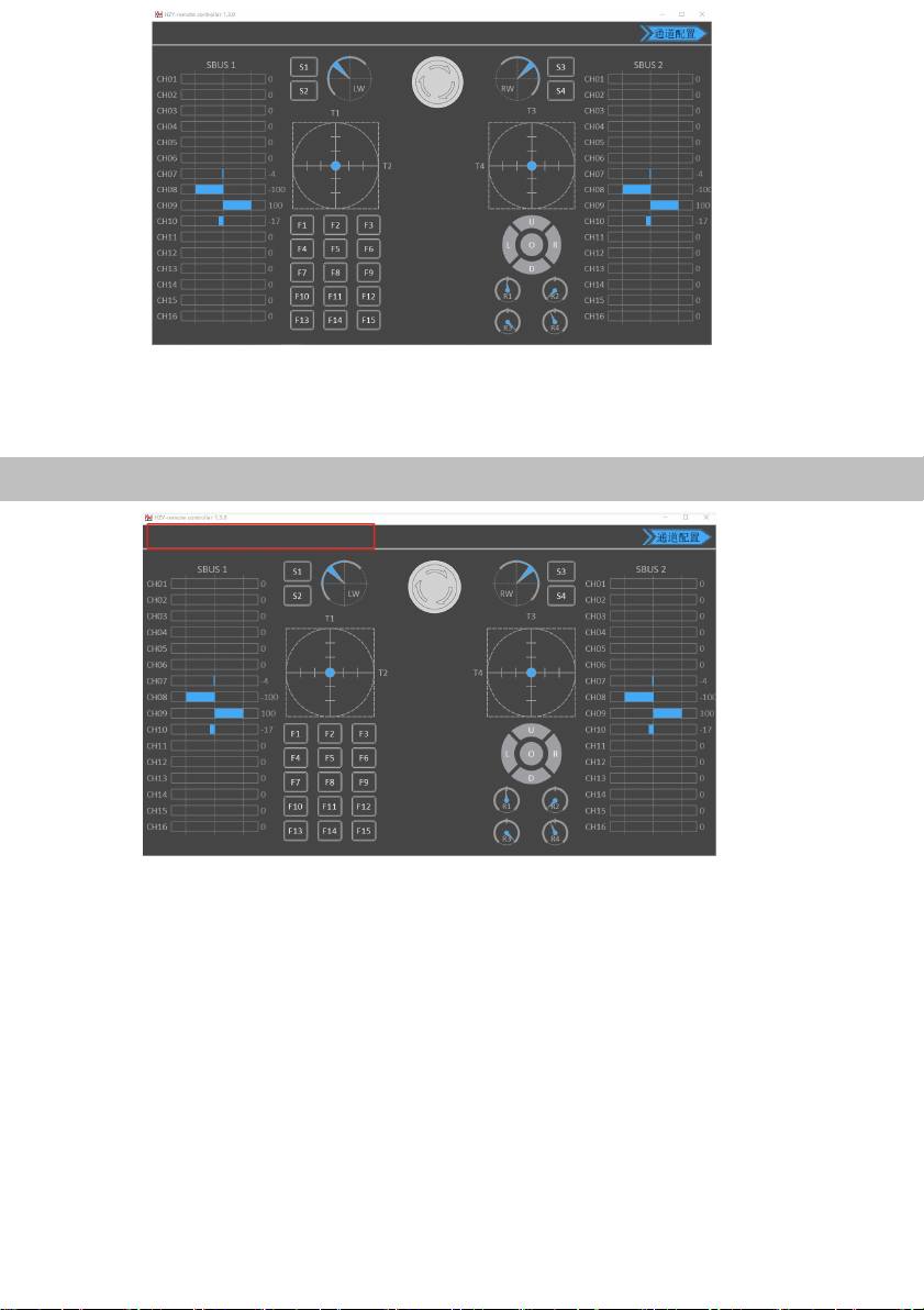
Channel Monitoring and Calibration
The figure above shows the channel monitoring interface, showing the status of
each channel of the remote control. When the remote control is in the wrong
position or there is a rudder phenomenon, click the red box position in the upper
left corner three times to bring up the option of remote control calibration
function, and calibrate each analog channel.
www.chinowing.com
17
Channel Configuration
Click <Joystick Calibration> to start calibration; toggle all the joysticks and knobs,
includingT1,T2,T3,T4,LW,RW,R1,R2,R3,R4 to ensure that all analog
channels touch the maximum value, the minimum value of stroke and then finally
to the middle position. Click to complete the calibration.
After the calibration is completed, toggle each joystick to see if the parameters
setting software display matches the action to verify that the calibration was
successful. When the R1,R2,R3,R4 knob switches hit the middle position, they
will give a“didi”sound.
The channel display of the remote control is divided into three parts. The left
part shows the output value of SBUS-1, the middle part shows the
corresponding status of each channel, and the right part shows the output
value of SBUS-2. SBUS1 and SBUS2 can be configured separately.

www.chinowing.com
18
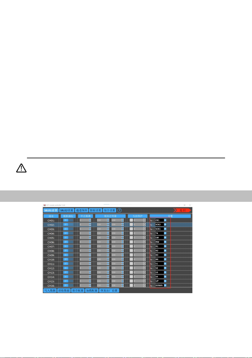
1. Click the channel configuration button. The above picture shows the
configuration interface. SBUS1 and SBUS2 can be configured respectively.
CH01-CH16 channels of each S-BUS are freely compatible with
T1 , T2 , T3 , T4 , LW,RW,R1,R2,R3,R4,F1-F15,S1-S4,UP,DOWN,
LEFT,RIGHT,OK,STOP.Among them, T1, T2, T3 and T4 are the main
joysticks; LW and RW are the returnable middle levers; R1,R2,R3,R4 are
knobs; F1-F15,S1-S4,UP,DOWN,LEFT,RIGHT,OK,STOP are 25 keys.
2. The servo phase can reverse the each channel of the remote control. The
midpoint trimming adjusts the pwm output value for each channel rocker in
the middle position, the adjustment range is from -125 to 125, and the linear
servo stroke amount -31 to 31. The steering stroke can be adjusted from -150
to 150. The default is -100 to 100. Do not adjust if there is no special need.
3.Fail-safe protection settings: click on the small white box, when there is a
<√> in the white small box, the fail-safe protection function of the current
channel works; set the value of the corresponding dialog box, the current
value is the pwm value of the out of control (after setting, please verify by
flight control, ground station or servo).
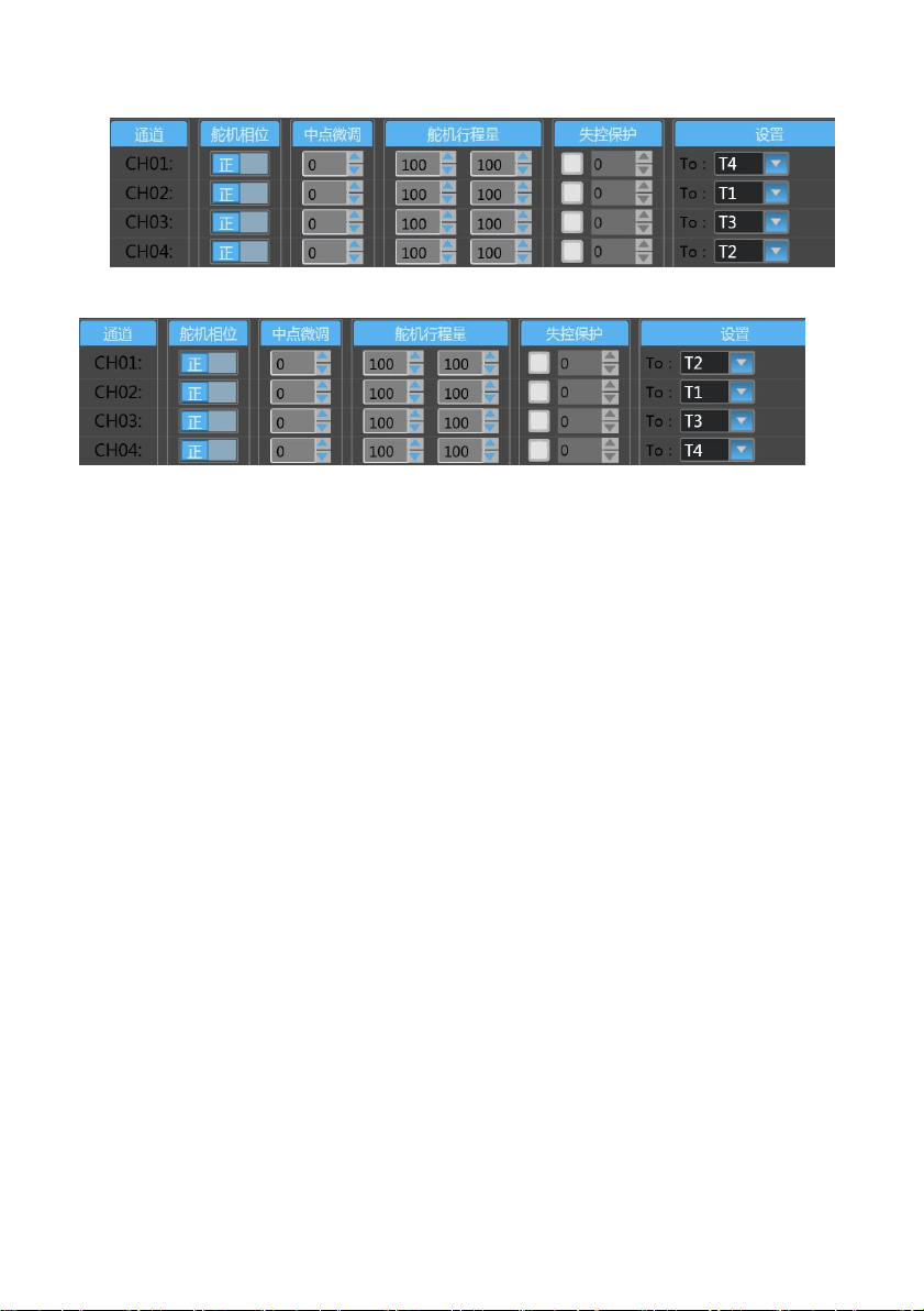
4.There are three operation modes: American mode, Japanese mode and Chinese
mode
American mode
www.chinowing.com
19
Japanese mode
Chinese mode
1. <CH1-CH16> in the red mark in the above figure is the configuration output of
the physical joystick, which can correspond to the physical channel or multiple
CHxx to one physical channel.
Read data: Click once to re-read configuration data
Write data: Click once to write a new configuration data
Load configuration: call different storage profiles
Save configuration: save the current configuration as a configuration
file for easy finding
Restore default: restore all parameters of the current page to default
values
www.chinowing.com
20
After each configuration change, click <write data button> and the changed
configuration can take effect.
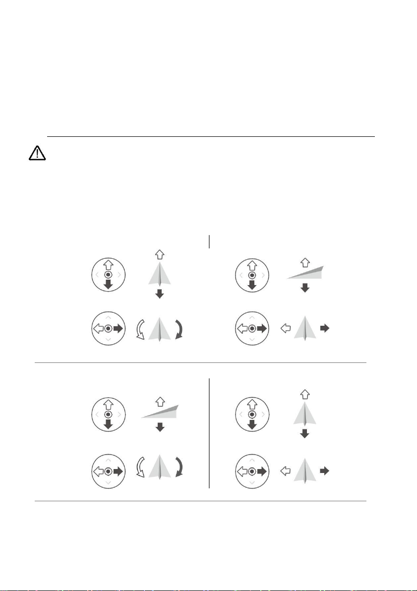
When the remote control mode is configured as American mode, Japanese mode and
Chinese mode, the control mode is shown below.
Japanese mode
左摇杆
前
右摇杆
上升
下降
后
左
右
左转
右转
American mode
左摇杆
右摇杆
前
上升
下降
后
左 右
左转 右转
Chinese mode
Table of contents
Other Chinowing Control System manuals


