Chinowing T21 User manual

1
www.chinowing.com
T21
Handheld Ground Control Station
User Manual V 1.2.7
2019.4

2
www.chinowing.com
Content
目录
1. Disclaimer ...........................................................................................4
2. Product Precautions ...........................................................................4
2.1 Installation Note.....................................................................4
2.2 Precautions for Use................................................................ 5
3. Product Introduction ..........................................................................5
4. Item List ..............................................................................................5
5. Product Instruction ............................................................................ 7
5.1. Airborne unit(receiver) R20 ................................................ 7
5.2. Remote Control Instruction..................................................8
5.3. Receiver R20 Installation and Connection.......................... 9
6. Remote Controller Operation .......................................................... 10
6.1. Power on and Power off of the Tablet .................................10
6.2. Power On and Power Off of the Remote Controller ............ 10
6.3. Indicator Instruction of Remote Controller and Receiver .... 11
7. RC Parameters Setting Software ......................................................12
7.1. Main Interface Instruction .................................................... 12
7.2. Channel Monitoring and Calibration .................................... 13
7.3. Channel Configuration .......................................................... 14
7.4. Throttle Hold .........................................................................19
7.5. Alarm Instructions for remote control ................................. 20
8. Receiver Pairing and Configuration ................................................. 22
8.1. Operation Instruction for H840 Parameters Pairing .............25
8.2. Operation Instruction for H900 Parameters Pairing .............26
9. Charge the Remote Controller .........................................................28
10. HID Controller ................................................................................ 28
11. Common Questions ....................................................................... 31
12. Firmware Upgrading Procedure .................................................... 31
12.1. Firmware version view ........................................................31
12.1. Remote Control Firmware Upgrade ................................... 32


4
www.chinowing.com
1. Disclaimer
Thank you for purchasing the T21 hand-held remote-control station. Please use it in
accordance with local radio control regulations and read this statement carefully before
using it. Once used, it shall be deemed to endorse and accept all contents of this statement.
Please strictly follow this instruction to install and use the product. The supplier will not
bear any legal liability for any result or loss caused by improper use, installation, final
assembly or modification of the product.
2. Product Precautions
1) T21 ground unit is matched with airborne unit R20 to use together.
2) The ground unit is with built-in 12v battery (3S lithium battery). The airborne end
needs external power input DC7.4-12V(2S-3S lithium battery). Please power the system in
strict accordance with specifications.
3) With improper operation, the aircraft may cause a certain degree of injury and damage
to human and the system, please be sure to pay attention to safety during use.
4) In order to better serve customers, our R&D team has been upgrading and optimizing
the product. The software and firmware will be upgraded frequently. There may be
incompatibilities between different firmware versions. Please pay attention to asking the
supplier for the latest software firmware and technical support.
5) Software and firmware version example: calling software: HZY_ToolBench V1.2.3.4;
Ground end firmware: TTX 30-1.2.3-1.0; airborne end R20 firmware: RSx16-1.2.3-1.0;
airborne end V20 firmware: V20RX-1.2.3-1.00.
6) The software, firmware, drivers, port conversion tools, etc. involved in this manual will
be updated from time to time on our website, please visit our website to download, or
contact us for more information.
7) If you encounter any problem that cannot be solved during installation or use of the
product, please contact us or visit our web www.chinowing.com
2.1 Installation Note
1) Be sure to use the spare parts provided by our company.
2) Be sure to install the antennas before power on to avoid damage to the circuit.

5
www.chinowing.com
3) Try to make the receiver antenna without obstruction, and the end part of the antenna is
vertically downward without bending, so as to avoid shortening the communication
distance or even failing to communicate due to obstruction.
4) Do not disassemble or refit without permission. If you encounter any problem that
cannot be solved during installation, please contact us directly.
5) During installation, keep proper distance between electronic devices to minimize
electromagnetic interference.
2.2 Precautions for Use
1) Before use, please make sure that all connection wires are fastened reliably and all parts
work normally.
2) Please open the configuration software of the remote control and check whether the
channels are normal.
3) Please check the surrounding environment to ensure that there is no interference from
other devices, otherwise T21 data transmission performance will be seriously affected.
4) Check the power of the remote control before use. If the parameter adjustment software
shows that power is low, please charge the remote control timely. If the remote control is
turned off, the receiver has entered the state of Fail-safe protection. Stop using it when the
battery is too low. Don't rely on the device's low-power alarm, which is only a precaution
and tells you when to charge. It takes about 5hs to be fully charged.
3. Product Introduction
T21 is a highly integrated system of remote controller, data link and ground control station.
With the compact size, easy operation, T21 has 16 adjustable Channels and dual SBUS
output, able to control the dorne and the payload simultaneously. Working under the
frequency of 840MHz/900MHz, it can transmit stable data at the max range of 30km. It has
been widely used in UAV, UGV, USV, etc.
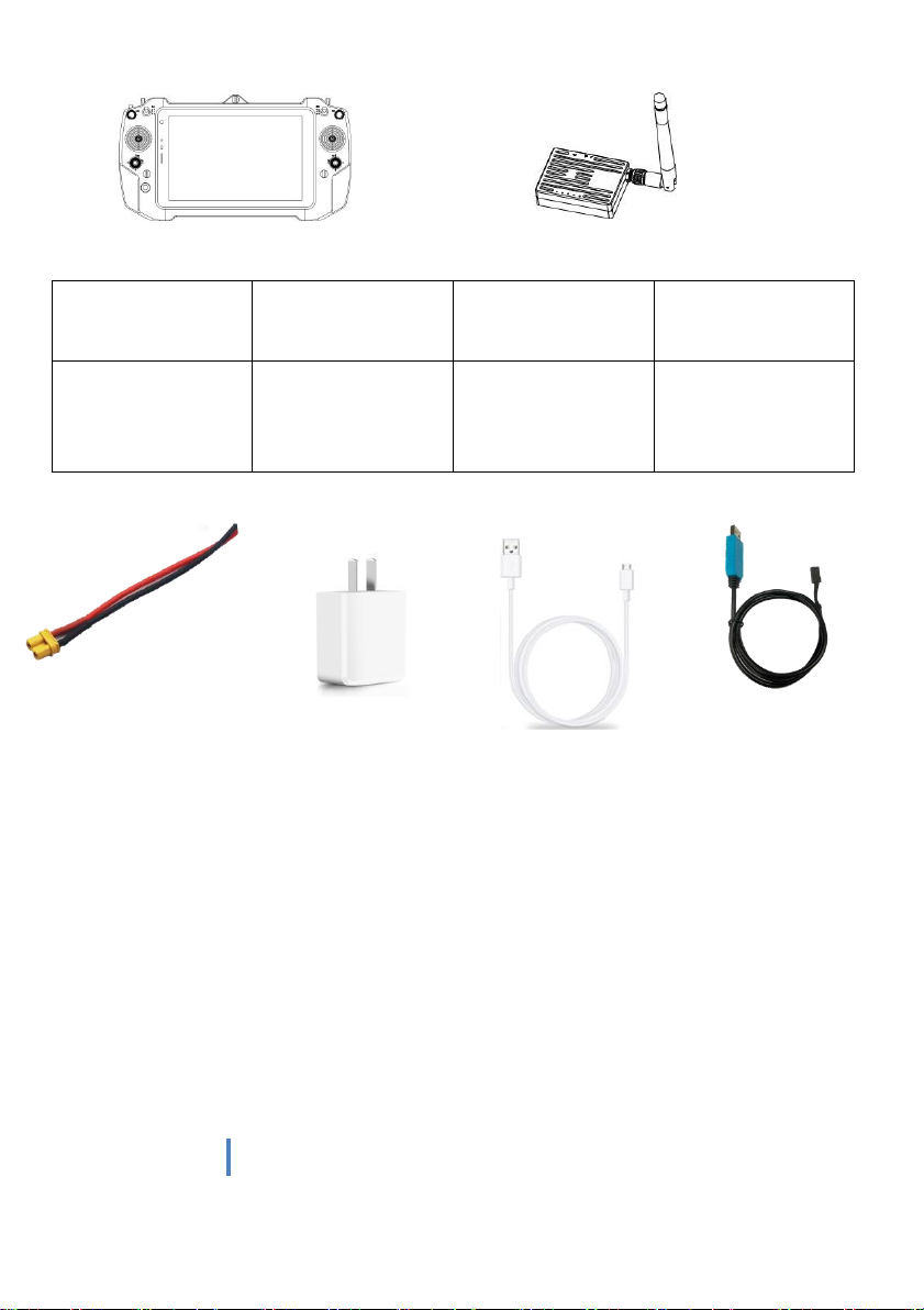
4. Item List
Main module
Remote controller x1
Airborne unit(receiver) x1
6
www.chinowing.com
Accessories
Power supply
cable*1
Charger*1
Receiver upgrade
configuration
line*1
Lan-to-4 pins
line*1
Power for receiver
(DC:7.4-12V, Li
battery 2s-3s)
Charge for remote
controller
Used for firmware
upgrading
and parameters
setting for receiver
For module
Parameter
configuration
7
www.chinowing.com
5. Product Instruction
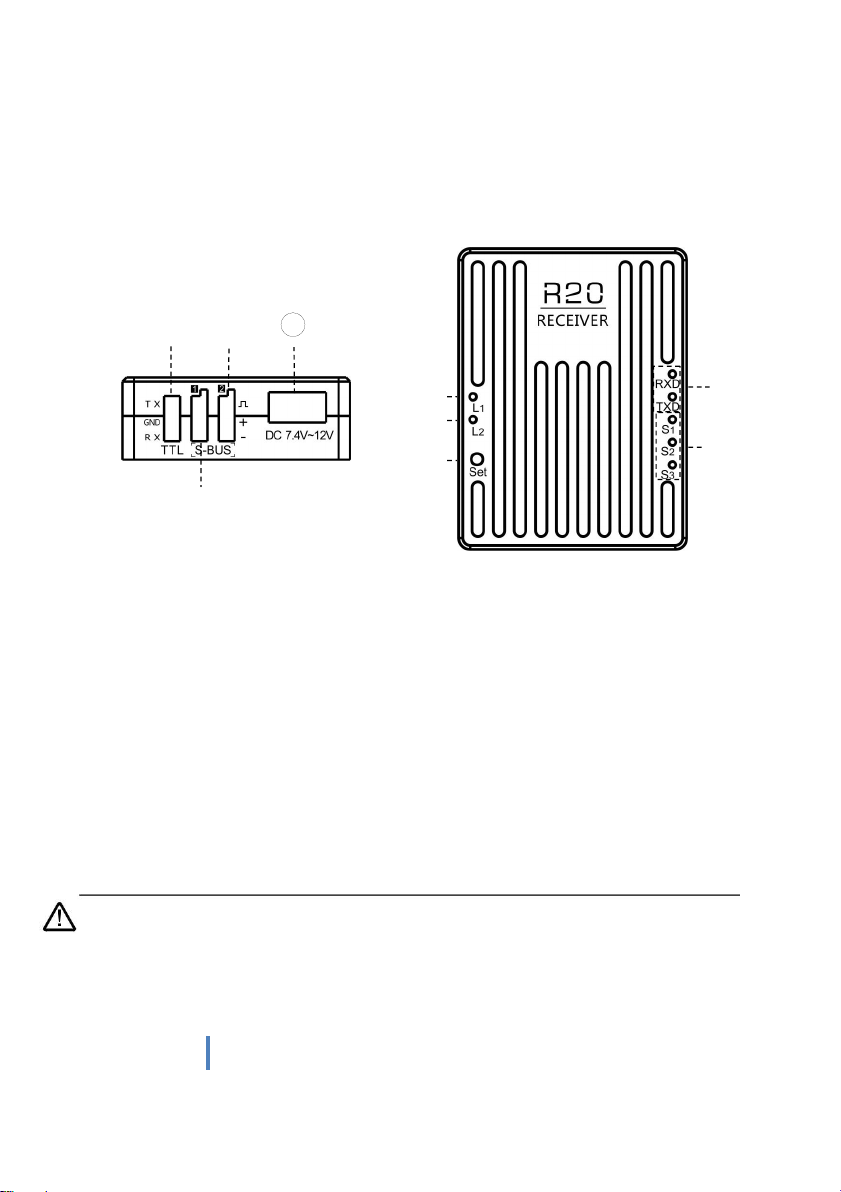
5.1. Airborne unit(receiver) R20
①Power supply interface: pls use XT30 plug to power, power supply: 7.4-12v
②COM port: TTL, used for connecting COM port or API prot of flight controller
③S-BUS1 interface: to connect flight controller or other devices
④S-BUS2interface: to connect flight controller or other devices
⑤Signal strength indicator: S3 ON, signal is weak; S3 and S2 ON, signal is moderate; S3, S2
and S1 ON, signal is strong.
⑥Data transmission indicator: RXD indictor ON means there is data receiving of the receiver;
TXD indictor ON means there is data transmitting of the receiver.
⑦S-BUS data indicator L1: used for indicating the communication status of remote
controller and receiver
⑧Receiver configuration mode indicator L2: used for indicating whether it is in the
confinguration mode
⑨SET button: frequency modulation button between remote controller and receiver
By default, the S-BUS1 and S-BUS2 interfaces output the CH1 to CH16 of the
remote control to 1-16 channels.
1
②
③
④
⑤
⑥
⑦
⑧
⑨

8
www.chinowing.com
5.2. Remote Control Instruction
①RC power button: turn on or turn off RC
②⑪Small joysticks: corresponding T5, T6, T7, T8, used for controlling gimbal or other
devices
③⑩ Large joysticks: used for controlling the flight(4 kinds of joystick mode can be set by
the parameters setting software)
④⑨Knob: LD&RD
⑤⑧Three-position switch: SA&SB
⑥Tablet power button: used for turn on or turn off tablet
⑦Charing indicator of tablet: used for indicating power status of tablet
⑫Type-C charging port: powering for tablet, Max charging current 3A
⑬Standard USB interface: used for externally connecting USB keyboard, mouse or USB flash
disc, etc
⑭⑰button: SF&SC
⑮⑯Three-position switch: SE&SD
⑧
③
⑩
1
②
④
⑤
⑥
⑦
⑨
○
11
○
12
○
13
○
14
○
15
○
16
○
17

9
www.chinowing.com
5.3. Receiver R20 Installation and Connection
1. Connecting antennas to SMA port of Rx.
2. Fix the receiver to the appropriate position of the aircraft by using double-sided tape.
3. As shown in the above photo, connecting COM port and S-Bus port of the R20 receiver to
your device by lead wire of servo.
RX
TX
S
S
Receiver GND
GND Flight controller, etc
Receiver +
+ Flight controller,
etc
TX
RX
-
-
4. With 7.4-12v DC power input, L1 indicator will flicker. That means the success
connection of transmitter and remote control.
5. If you are using a dual S-Bus receiver, both S-Bus1 and S-Bus2 output CH1 to CH16 from
the remote control. And the output of S-Bus1 and S-Bus 2 can be mapped separately. See
the output mapping description.
Flight controller
Other devices
to receive
SBUS signal

10
www.chinowing.com
The default power of the receiver: 1W. Please keep the antenna away from other
electronic devices (GPS, compass, etc.) to avoid interference.
Be sure to install the antenna before power on, otherwise it may burn out the radio
module.
When using, try to make the antenna face down and without any obstacle to block,
so as to avoid the communication distance being shortened due to blocking, or even unable to
communicate.
Be sure to use the specified type of antenna and install it correctly. Do not use other
types of antennas.
6. Remote Controller Operation
6.1. Power on and Power off of the Tablet
1. Long press the power button. Release it when you see the power-up screen.
2. After the computer is turned on, you can check the remaining battery power through
indicator icon in the lower right corner of the desktop. If less than 20% power, please
charge timely.
3. After finishing the operation, pls power off the computer through the computer shutdown
interface.
When you do not use your computer for a long time, please turn it off in time to avoid
the power consumption.
If it is found that the long press the power button cannot start up the system, it is
likely that the battery is with low capacity. Please charge it by standard adapter.
6.2. Power On and Power Off of the Remote Controller
Power on: long press for 5s
Power off: long press for 5s

11
www.chinowing.com
6.3. Indicator Instruction of Remote Controller and
Receiver
RC Indicator Instruction
RC indicator
Prompt tone
Status
Red ON
D-prolonged sound
Power on successfully
Red OFF
D-prolonged sound
Power off successfully
Red flashing
D-D-D...
Low battery alarm
Receiver indicator Instruction
Receiver Indicator
Status
L1 indicator
flashing
Successful connection of receiver and RC
L2 indicator
ON
Receiver in the configuration mode, no
power output
RXD indicator
flashing
There is data receiving for receiver
TXD indicator
flashing
There is data transmitting for receiver
Indicator S1, S2, S3
ON or flashing
Strong signal
Indicator S2, S3
ON or flashing
Moderate signal
Indicator S3
ON or flashing
Weak signal
Receiver Indicator Instruction
With the remote control and receiver properly connected and with good signal strength,
please distinguish whether your device is the P900 version or the H840 version.
1. For P900 version, if the signal strength indicator RS1,RS2,RS3 on the remote control is in
running horse mode and the signal strength indicator S1,S2,S3 on the receiver is off, it means
that there is no connection. If both remote control and receiver signal strength indicators are
on, it means successful connection.
Note: The P900 version will show successful connection only after sending and receiving
data.
2. For H840 version. With the remote control and the receiver properly connected and with
good signal strength, the receiver indicators should be as:
L1 flashing, L2 light , RXD flashing, TXD flashing, S1 continuously ON, S2 continuously ON, S3
flashing.

12
www.chinowing.com
7. RC Parameters Setting Software
7.1. Main Interface Instruction
1) T21 parameters setting software is integrated into Chinowing tablet. Start the remote
controller and tablet, then open the Chinowing Tool Platform and enter the main interface as
shown in above.
2) Double click the icon of "Parameters Setting Software".
3) "Firmware Upgrade" can be used to upgrade the firmware of the remote control and the
receiver, other methods will be introduced in the following chapters. "Radio (P)" can be used
to configure parameters for P900 module. "Radio (H)" can be used to configure parameters
for H840 module.

13
www.chinowing.com
7.2. Channel Monitoring and Calibration
1)The figure above shows the channel monitoring interface, showing the status of each
channel of the remote control. When the remote control is in the wrong position or there is a
rudder phenomenon. Click the red box area in the upper left corner three times to bring up
the remote control calibration function option
1.1)Click <Joystick Calibration> to start calibration; toggle all the joysticks and
knobs, including T1, T2, T3, T4, T5, LD, RD, T6, to ensure that all analog channels
touch the maximum value, the minimum value of stroke and then finally to the
middle position. Click to complete the calibration.
After the calibration is completed, toggle each joystick to see if the parameters
setting software display matches the action to verify that the calibration was
successful. When the RD and LD knob switches hit the middle position, they will give
a“didi”sound.
2)The lower left is the message area. The detailed message is described as below.
2.1)”Flight control connection port:COM44”,it means the normal communication of
the RC and the tablet. COM44 is the port number assigned by the tablet PC to the data link,
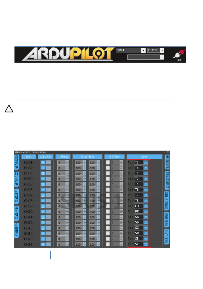
14
www.chinowing.com
which is used when the ground control station is connected to the flight controller. This is
shown in the following figure.
2.2) "RC port not found", this message indicates that the tablet does not correctly
recognize the remote control port.
The T21 is not working properly. Please refer to "FAQ 5" to try to fix it.
2.3) USBHUB is re-inserted, this message indicates that communication of the remote
control and the tablet has been restored. T21 is working normally.
There are three parts of the RC channel display , the left part represents the output
value of SBUS-1, the middle part represents the corresponding state of the remote control
joysticks, and the right part represents the output value of SBUS-2. SBUS-1 and SBUS-2 can be
configured separately.
7.3. Channel Configuration

15
www.chinowing.com
1) Click the channel configuration button. The above picture shows the configuration
interface. SBUS1 and SBUS2 can be configured respectively. CH01-CH16 channels are
freely compatible with T1 , T2 , T3 , T4 , LD,RD,SA,SB,SC,T5,T6,T7,T8,
SC,SD,SE,SF. LD,RD are knobs,SA,SB,SD,SE are three-position switches, SC,
SF are buttons,T1 , T2 , T3 , T4 are main joysticks,T5,T6,T7,T8 are auxiliary
joysticks.
2) The servo phase can reverse the each channel of the remote control. The midpoint
trimming adjusts the pwm output value for each channel rocker in the middle position,
the adjustment range is from -125 to 125, and the linear servo stroke amount -31 to 31.
The steering stroke can be adjusted from -150 to 150. The default is -100 to 100. Do not
adjust if there is no special need.
3) Out of control protection settings: click on the small white box, when there is a <√>
in the white small box, the out of control protection function of the current channel
works; set the value of the corresponding dialog box, the current value is the pwm value
of the out of control (after setting, please verify by flight control, ground station or
servo).
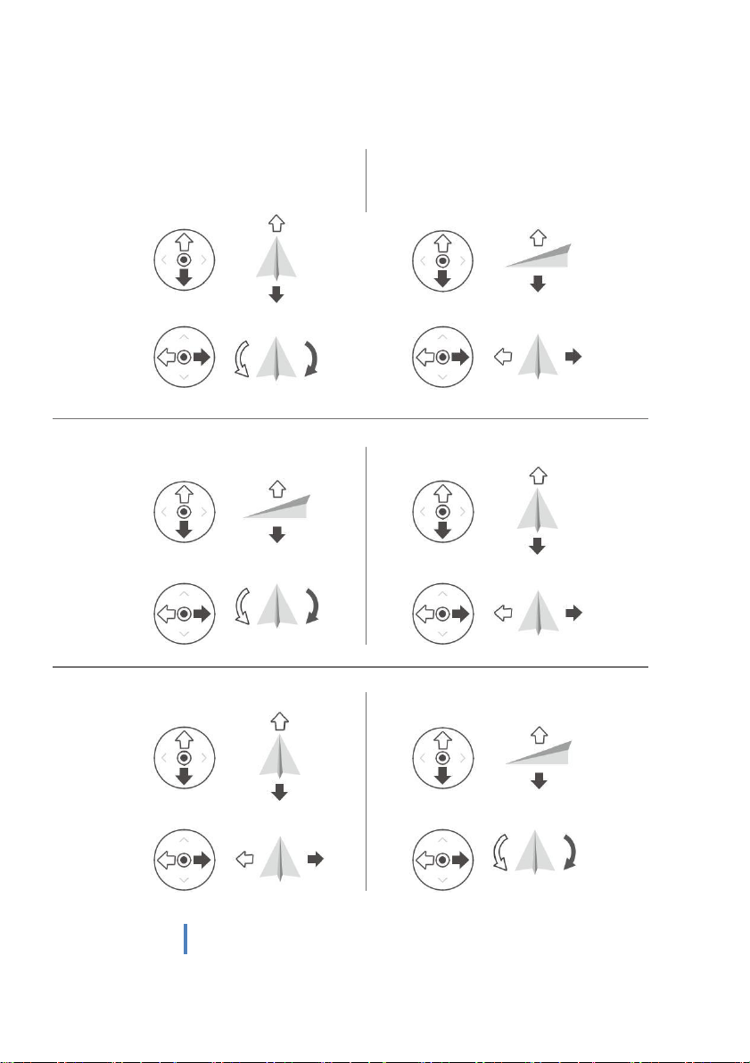
4) There are three modes: American operation mode, Japanese operation mode and Chinese
operation mode
American operation mode:
Japanese operation mode:
Chinese operation mode:

16
www.chinowing.com
5) <CH1-CH16> in the red mark in the above figure is the configuration output of the
physical joystick, which can correspond to the physical channel or multiple CHxx to one
physical channel.
Read data: Click once to re-read configuration data
Write data: Click once to write a new configuration data
Load configuration: call different storage profiles
Save configuration: save the current configuration as a configuration file for
easy finding
Restore default: restore all parameters of the current page to default values
After each configuration change, click <write data button> and the changed configuration
can take effect.
When the RC operation mode is American mode, Japanese mode and Chinese mode, the
operation method is as below:
17
www.chinowing.com
Japanese operation mode
左摇杆
前
右摇杆
上升
下降
后
左
右
左转
右转
American operation
mode
左摇杆
右摇杆
前
上升
下降 后
左 右
左转 右转
Chinese operation mode
左摇杆 前右摇杆 上升
下降
后
左 右 左转 右转
18
www.chinowing.com
The default operation mode is the American mode. This manual uses the American hand as
an example to illustrate how the remote control is operated.
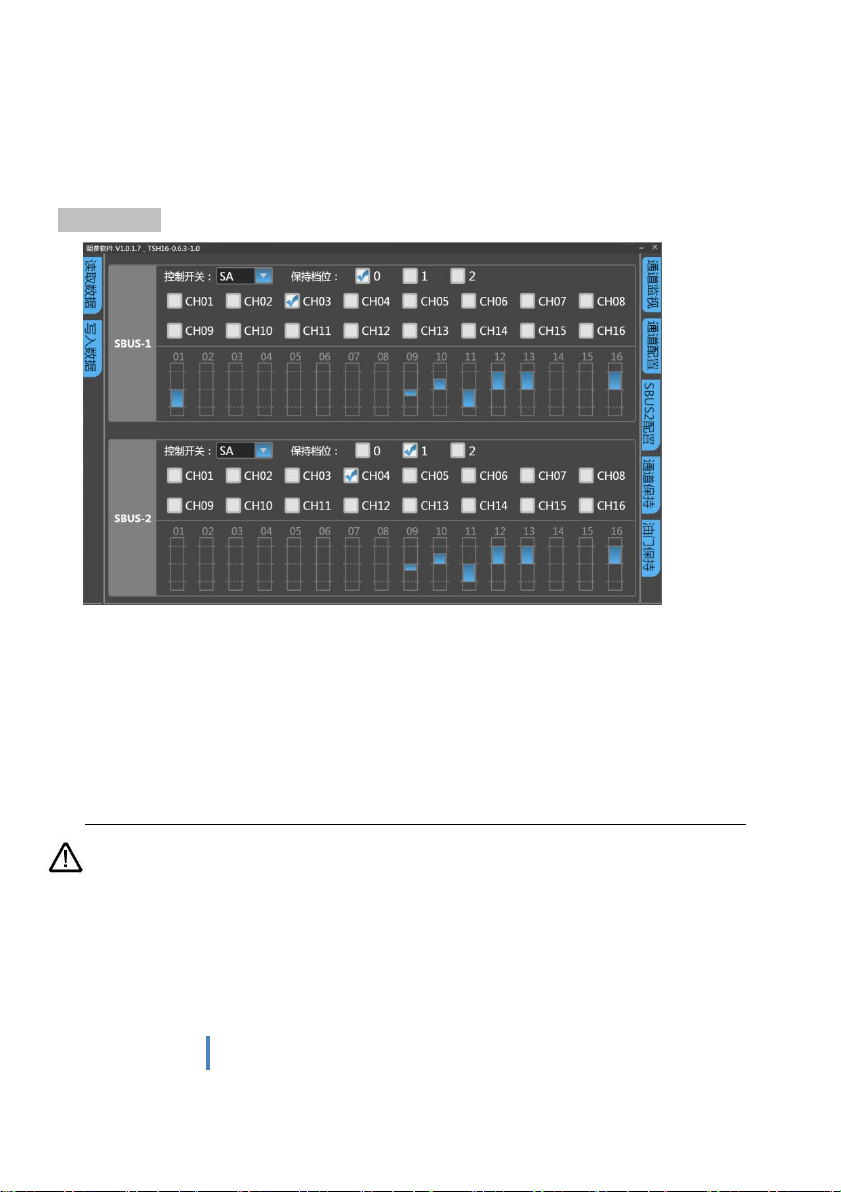
Channel Hold
1) Select channel hold control switch
2) Select the gear position where the control switch trigger remains."0" represents low gear,
"1" represents middle gear and "2" represents high gear. Three gears can be used separately.
3) Choose the channel hold.
4) Write data and verify the results. As shown in the figure above, for SBus-1, if SA is set to a
low level, the output of CH3 can be triggered to maintain, and CH03 cannot control the output
value of 03.The 03 channel will always hold its current value.
The channels of sbus-1 and sbus-2 operate independently.
The channel hold priority should be over the throttle control.
19
www.chinowing.com
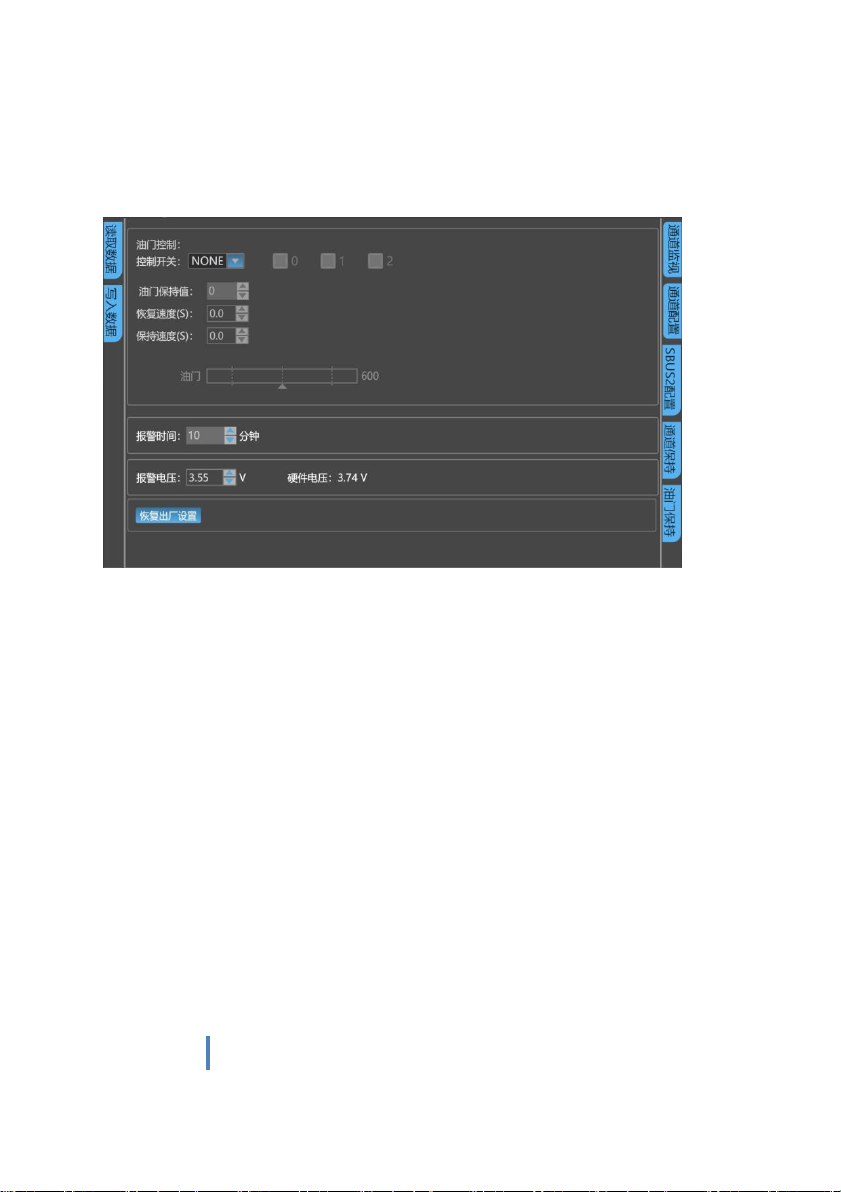
7.4. Throttle Hold
1. Select throttle control switch
2. Select the gear position where the control switch trigger remains. ‘0’ represents low gear,
‘1’ represents middle gear and ‘2’ represents high gear. Three gears can be used separately.
3. Enter throttle retention value.
4. Enter throttle holding and restore speed, 30 Max. The bigger value means the slower
speed.
5. Write data and verify. As shown above, if SB is set low gear, the throttle will maintain the
speed of "30" to reach the set output value of 150. After dial SB to the other gears, the
throttle will restore the value of the throttle control channel at the throttle restore rate of
"30".
6. Alarm time is the alarm time when the joystick does not operate for a long time. The
default is 10 minutes, adjustable from 0 to 120 minutes.
7. Alarm voltage is the alarm voltage of low power of the remote control. Default 3.55v,
adjustable.
8. Hardware voltage is the real-time voltage of remote control battery.
9. Restore Factory Setting. T21 is with powerful function, so there are many parameters that
can be set. We can restore the factory settings of T21 with one key. Step as below:
①Enter the restoring factory setting interface and click it, and the system will pop up a
warning prompt to confirm the option again. Warning: restoring factory settings will clear
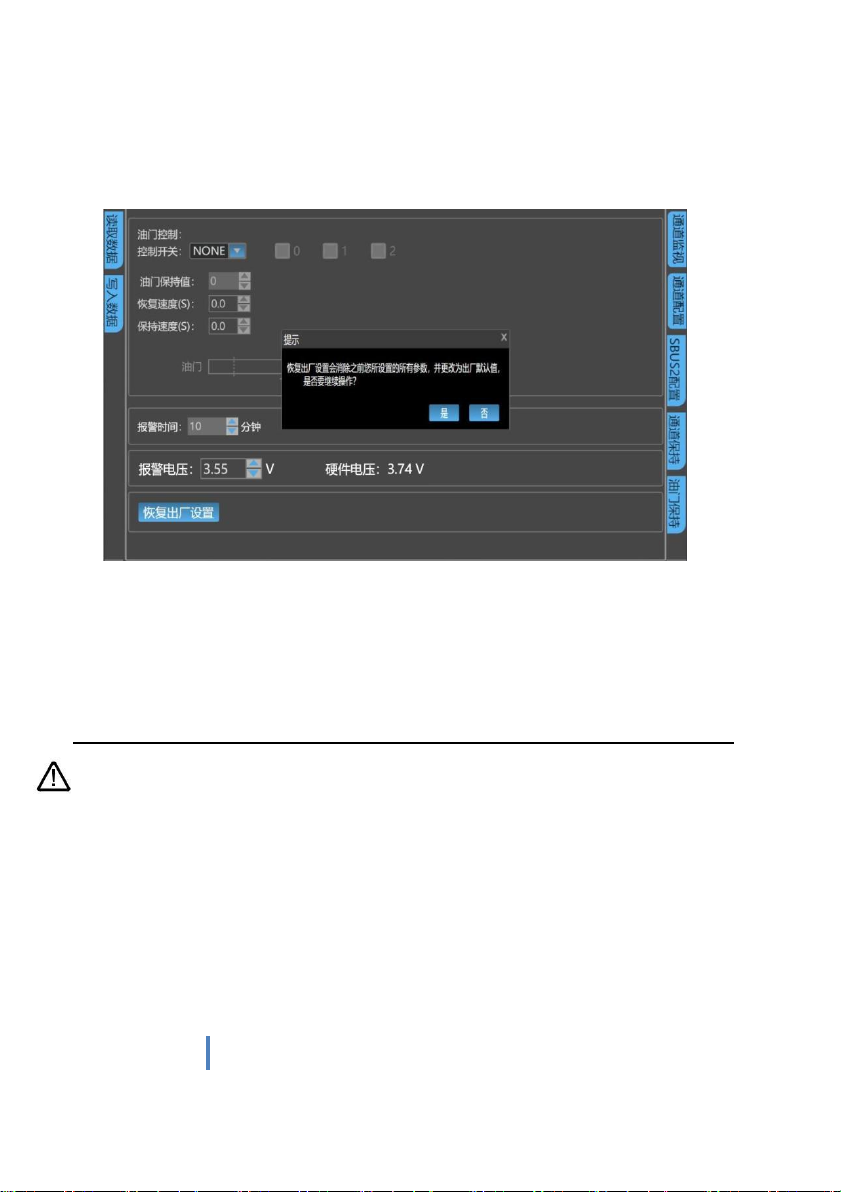
20
www.chinowing.com
all parameters you set before, and change to factory default value, whether to continue the
operation?
②If the operation is wrong, click NO button. If you do want to restore all parameters to
factory Settings, click OK.
③ After restoring factory settings, all parameters (including analog channel calibration,
SBUS setting, channel holding, throttle holding, idle alarm time, low voltage alarm
voltage, etc.) will be restored to factory default values.
Throttle hold only works on sbus-1.
7.5. Alarm Instructions for remote control
Joystick long time not working alarm: The remote control will emit a continuous alarm
sound of ‘didi’ when all joysticks or dial levers fail to work for long time beyond the set alarm
time (the default time is 10 minutes, which can be adjusted in the adjusting software). At this
time, stir any joystick or dial lever and the alarm sound will automatically turn off. When the
‘alarm time’ is set to 0 minutes, the alarm function will be canceled.
Table of contents
Other Chinowing Control System manuals


Popular Control System manuals by other brands


Lutron Electronics
Lutron Electronics Energi Savr Node QS DALI installation guide

Beckett
Beckett GENISYS 52040 Product sheet

GSI Group
GSI Group II Sweep Series owner's manual

Raven
Raven Viper Pro Installation & operation manual

British Gas
British Gas EnergySmart User instruction

Trio
Trio UNIPLAY HMI quick start guide


