Chinowing VM21 User manual
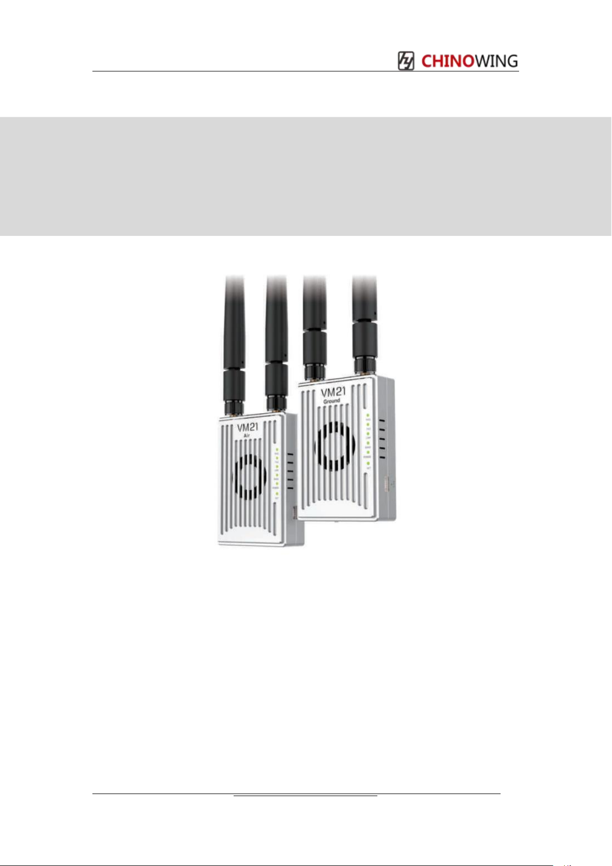
VM21 Mesh Radio
User Manual V.202305
Manufacturer: Chinowing Technology Co., Ltd
Address: Room 1106, Building B4, Yunzhi Park, No.138, Xingxin Road, Guangming
Street, Guangming District, Shenzhen City, Guangdong Province, China, 518107
Thank you for choosing our products. Please read these user manual carefully before
use.
Chinowing Technology Co., Ltd

PREFACE
Disclaimer
Thank you for purchasing the VM21 Mesh Radio Link. Please use it in accordance with the
local radio control regulations and read this statement carefully before using it. Once used, it
shall be deemed to endorse and accept all contents of this statement. Please strictly follow
this instruction to install and use the product. The supplier will not bear any legal liability for
any result or loss caused by improper use, installation, final assembly or modification of the
product.
Product Precautions
1. VM21 airborne unit and ground unit need external power supply input DC7.4-24V
(lithium battery 2s-6s), please follow the specification to power the radio.
2. Be sure to install the antenna before powering up to avoid damaging the circuit.
3. Ensure that the antennas are free from obstruction and bending, and keep it as far away
from large metal objects as possible to avoid blocking communication for the above reasons.
4. Please do not disassemble or modify the VM21. If you encounter any problems that
cannot be solved during installation or use, please contact Chinowing Technology Co., Ltd.
5. Make installation with proper distance between electronic devices to minimize
electromagnetic interference.
6. Before use, make sure that all wiring is securely fastened and that all components are
working properly.
7. Please check the surrounding environment to ensure that there is no interference from
other devices in the same frequency band before use, otherwise the data transmission of
VM21 may be seriously affected
8. If you encounter any problem during the installation or use , please contact us or visit our
website at www.chinowing.com for technical support.
Chinowing Technology Co., Ltd

目录
Chinowing Technology Co., Ltd
Catalog
目录
Chinowing Technology Co., Ltd .................................................................................................. 1
Product Precautions ...................................................................................................................2
VM21 may be seriously affected .................................................................................................2
Catalog ........................................................................................................................................ 3
1. Product Introduction .............................................................................................................. 4
1.1 Product Introduction and Parameters ............................................................................... 4
1.2 Antenna mounting intent .....................................................................................................5
1.3 Indicators And Interfaces Instruction .................................................................................6
2. Item List ................................................................................................................................. 8
2.1 Main Module .........................................................................................................................8
2.2 Accessories .......................................................................................................................... 8
3. Product Use ...........................................................................................................................9
3.1 Preparation ...........................................................................................................................9
3.2 Serial Port Operation ...........................................................................................................9
3.3VM21 status LED description ......................................................................................... 10
3.4 S-BUS Operation ...............................................................................................................11
3.5 LAN Operation ................................................................................................................... 11
3.6 USB Operation ...................................................................................................................13
3.7 Mesh Operation ................................................................................................................. 14
3. 8 Module Configuration ........................................................................................................ 15
4. Remote Control Fail Safe Protection .................................................................................19
4. 1 Write fail safe protection data ........................................................................................... 19
4.2 Trigger Fail Safe Value ..................................................................................................... 19
4.3 Turn off Fail Safe Value .................................................................................................... 20
4.4 Reset fail-safe data ............................................................................................................20
5. Firmware ..............................................................................................................................20
5.1 Firmware Version View ..................................................................................................... 20
5. 2 Firmware Upgrading .......................................................................................................... 21
6. Common Questions ............................................................................................................ 22
www.chinowing.com
Chinowing Technology Co., Ltd
1. Product Introduction
1.1 Product Introduction and Parameters
VM21 is mesh radio developed based on LTE, OFDM, MIMO. With dual 10/100 Ethernet
and serial gateway functions, it provides reliable wireless Ethernet bridge functions and
gateway services for most devices. VM21 combines smooth integration with 3-in-1(video,
telemetry, RC) link for a faster, more cost-effective path to system fielding. There are 3
frequencies for choice, 800MHz, 1.4GHz and 2.4GHz. Parameters are as below: It features
compact size, high integration, high sensitivity, which provides great convenience for the
user.
Item
Parameters
Description
Frequency
800MHz
1.4GHz
2.4GHz
806~826MHz
1427.9~ 1467.9MHz
2401.5~2481.5MHz
RF power
-40 – 25dBm
Adjustable
Transmission range
10KM
LOS
S-BUS port
2 S-BUS
NA
Serial port
1 channel
Simplex, baud rate
adjustable
Latency
200-300ms
Power supply voltage
7.4 – 24V
NA
Bandwidth
1.4M – 20M
1.4M\3M\5M\10M\20M
Video input/output
LAN
Connecting IPC or PC
Range of bands and frequency pointsfor each frequency band of the module.
Frequency band
Frequency range
Frequency point range
2.4GHz
2401.5-2481.5MHz
24015-24815
800MHz
806~826MHz
8060-8260
1.4GHz
1427.9-1467.9MHz
14279- 146790
www.chinowing.com
Chinowing Technology Co., Ltd
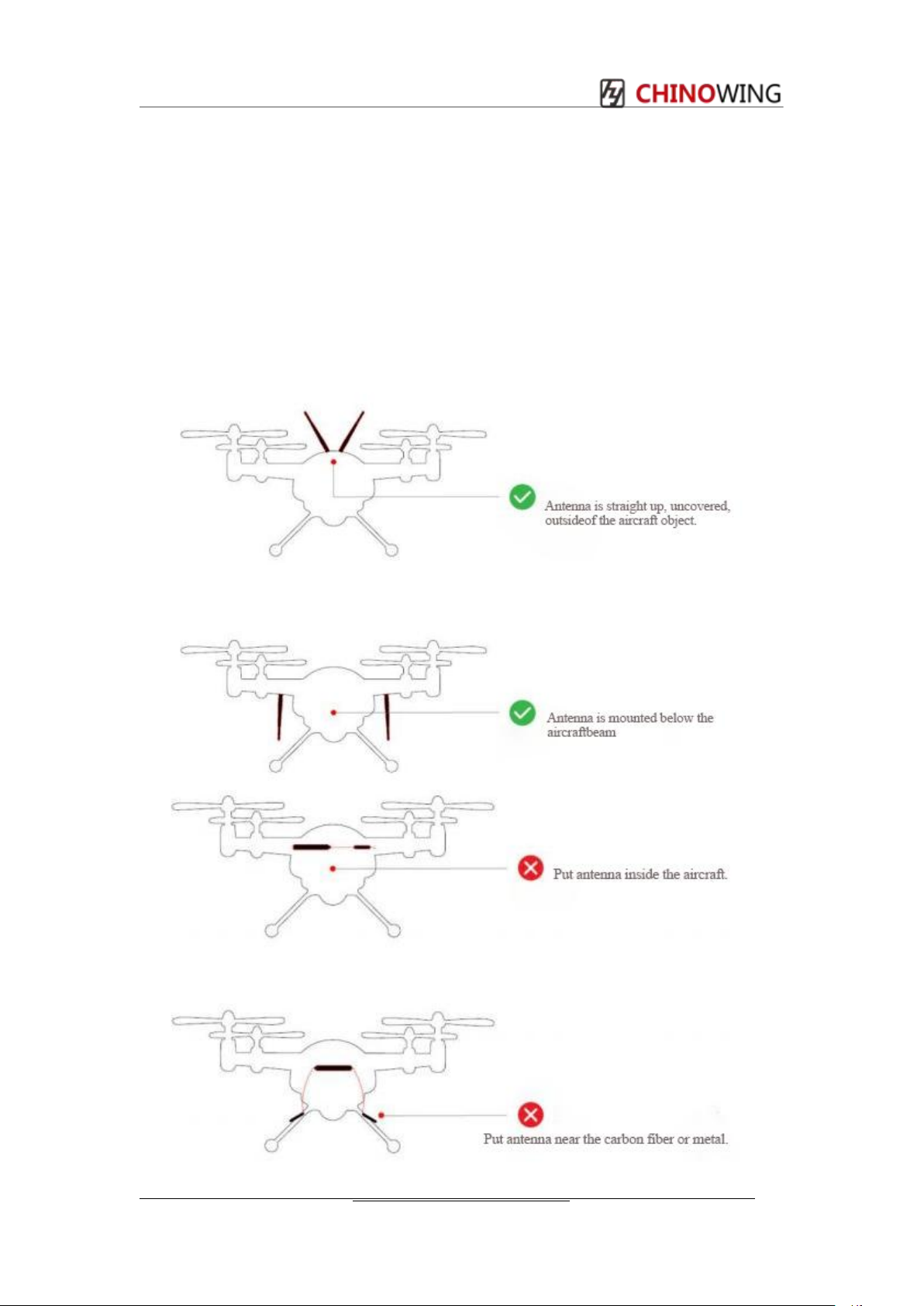
1.2 Antenna mounting intent
1.Keep the antenna tightly with the SMA interface;
2.Keep the antenna on the AIR side uncovered, and straight up, or straight down;
3.Keep the antenna on the GND side uncovered, and parallel with the one on the AIR side;
4.Keep metal objects away from the antenna to avoid the communication loss;
5.Use the antenna with high quality;
6.May adjust the antenna’s angle to improve the signal strength;
Table of contents
Other Chinowing Radio manuals


