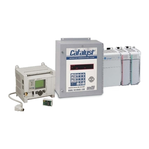
Chipkin Modbus CAS2500-01 User manual

Toll Free: 1 866 383-1657
3381 Cambie St., #211 Vancouver, BC Canada V5Z 4R3
Chipkin™ Modbus® RTU Data Client USER MANUAL
VERSION: 0.19
PRODUCT NUMBER: CAS2500-01
DOCUMENT REVISION: 1

Chipkin™ Modbus® RTU Data Client User Manual
3381 Cambie Street, #211 © 2018 Chipkin Automation Systems
Vancouver, BC, Canada, V5Z 4R3 All rights reserved
1-866-383-1657 Chipkin.com Page 2of 55
TABLE OF CONTENTS
TABLE OF CONTENTS .........................................................................................................................................2
LIST OF FIGURES ...................................................................................................................................................4
LIST OF TABLES .....................................................................................................................................................5
COPYRIGHT & TRADEMARKS ...........................................................................................................................6
DISCLAIMER ...........................................................................................................................................................6
CONFIDENTIALITY ...............................................................................................................................................6
DOCUMENT REVISION HISTORY.....................................................................................................................6
1. PREFACE..................................................................................................................................................................7
WELCOME ...................................................................................................................................................7
CHIPKIN........................................................................................................................................................7
SAFETY WARNINGS ..................................................................................................................................7
CUSTOMER SUPPORT ..............................................................................................................................7
2. OVERVIEW..............................................................................................................................................................9
PRODUCT SUMMARY...............................................................................................................................9
SYSTEM OVERVIEW..................................................................................................................................9
OPTIONAL EXPANSION MODULES......................................................................................................9
INSTALLATION AND CONFIGURATION SUMMARY........................................................................9
DEVICE WIRING REQUIREMENTS.........................................................................................................9
3. CONNECTIONS ...................................................................................................................................................10
NETWORK CONNECTIONS...................................................................................................................10
COMUNICATION PORTS .......................................................................................................................11
WIRING CONNECTIONS ........................................................................................................................11
PIN-OUT..........................................................................................................................................11
4. CONFIGURATION AND SETTINGS.................................................................................................................12
MODBUS RTU CONFIGURATION SETTINGS ...................................................................................12
Modbus RTU Configuration Page...............................................................................................12
Modbus RTU Task Configuration ...............................................................................................12
Modbus RTU Port Settings ..........................................................................................................14
MODS FOR DATA CONVERSION ........................................................................................................17
DATA LOGGING CONFIGURATION....................................................................................................21
Logging Raw Data..........................................................................................................................21

Chipkin™ Modbus® RTU Data Client User Manual
3381 Cambie Street, #211 © 2018 Chipkin Automation Systems
Vancouver, BC, Canada, V5Z 4R3 All rights reserved
1-866-383-1657 Chipkin.com Page 3of 55
Logging Modified Data .................................................................................................................23
Configuring Data Logging.............................................................................................................25
Completing the Configuration ................................................................................................................30
Resetting the Gateway or Deleting the Configuration ......................................................................31
Exporting the Configuration....................................................................................................................32
Importing the Configuration....................................................................................................................33
5. COMMISIONING, DIAGNOSTICS, AND TROUBLE-SHOOTING .............................................................36
WHAT TO TAKE TO SITE FOR COMMISSIONING ..........................................................................36
Software...........................................................................................................................................36
Hardware .........................................................................................................................................36
DISCOVER GATEWAY’S IP ADDRESS.................................................................................................37
Setup reference card.....................................................................................................................37
Using the IP Setup tool .................................................................................................................38
DEFAULT USERNAME AND PASSWORD ..........................................................................................38
DEBUG LOG OR WIRESHARK LOG.....................................................................................................39
Debug logging.................................................................................................................................39
Wireshark log..................................................................................................................................39
CHANGE THE GATEWAY IP ADDRESS ..............................................................................................39
UPDATE FIRMWARE ...............................................................................................................................40
APPENDIX A: SAFETY WARNINGS.....................................................................................................................43
APPENDIX B: HARDWARE SPECIFICATIONS ..................................................................................................44
APPENDIX C: SUPPORTED MODBUS FUNCTIONS.......................................................................................48
APPENDIX D: SOFTWARE VERSION –COM PORT .......................................................................................49
APPENDIX E: LIMITED WARRANTY ...................................................................................................................51
THANK YOU..............................................................................................................................................................55

Chipkin™ Modbus® RTU Data Client User Manual
3381 Cambie Street, #211 © 2018 Chipkin Automation Systems
Vancouver, BC, Canada, V5Z 4R3 All rights reserved
1-866-383-1657 Chipkin.com Page 4of 55
LIST OF FIGURES
Figure 3.1-1 - Network Connections Block Diagram ........................................................................................10
Figure 4.1-1 - Modbus RTU Configuration Link.................................................................................................12
Figure 4.1-2 - Modbus RTU Task Insert Link......................................................................................................13
Figure 4.1-3 - Modbus RTU Task Form ...............................................................................................................13
Figure 4.1-4 - Successfully Added Modbus RTU Task......................................................................................14
Figure 4.1-5 - System Page Link............................................................................................................................15
Figure 4.1-6 –ModbusRTU Ports Link ................................................................................................................15
Figure 4.1-7 - Default ModbusRTU Port Settings .............................................................................................16
Figure 4.1-8 - Modbus RTU Port Form................................................................................................................16
Figure 4.2-1 - Mods Configuration Link...............................................................................................................17
Figure 4.2-2 - Insert Mod Link ...............................................................................................................................17
Figure 4.2-3 - Mod Form.........................................................................................................................................18
Figure 4.2-4 –Example 1 of Mod Form Filled....................................................................................................19
Figure 4.2-5 - Example 2 of Mod Form Filled.....................................................................................................20
Figure 4.2-6 - Summary of Mods ..........................................................................................................................20
Figure 4.3-1 - System Page Link............................................................................................................................21
Figure 4.3-2 - Modbus TCP and RTU Tasks Link ...............................................................................................22
Figure 4.3-3 - Modbus RTU Tasks ........................................................................................................................22
Figure 4.3-4 - Edit Modbus Task ...........................................................................................................................23
Figure 4.3-5 - Task Data Table Changed .............................................................................................................23
Figure 4.3-6 - Mod Configuration Form - Data Logging ..................................................................................24
Figure 4.3-7 - Edit Mod Link ..................................................................................................................................24
Figure 4.3-8 - Edit Mod Form for Data Logging.................................................................................................25
Figure 4.3-9 - Mod Edited for Data Logging.......................................................................................................25
Figure 4.3-10 - Data Logging Configuration Link ..............................................................................................26
Figure 4.3-11 - Data Logging Points.....................................................................................................................26
Figure 4.3-12 - Data Logging Task Configuration Link.....................................................................................27
Figure 4.3-13 - Data Logging Task Insert Link....................................................................................................27
Figure 4.3-14 - Data Logging Task Form .............................................................................................................28
Figure 4.3-15 - Inserted Data Logging Task........................................................................................................29
Figure 4.3-16 - Data Logging Files Link ...............................................................................................................29
Figure 4.3-17 - Log Files .........................................................................................................................................30
Figure 4.4-1 - Save Database Link ........................................................................................................................30
Figure 4.4-2 - Save Database Successful.............................................................................................................31
Figure 4.4-3 - Reboot System Link .......................................................................................................................31
Figure 4.4-4 - Reboot System Count....................................................................................................................31
Figure 4.5-1 - Delete Database Link.....................................................................................................................32
Figure 4.5-2 - Delete Database Successful .........................................................................................................32
Figure 4.6-1 - Generate Configuration File Link ................................................................................................33
Figure 4.7-1 - Import Configuration .....................................................................................................................33
Figure 4.7-2 - Import File Browser........................................................................................................................34
Figure 4.7-3 - Configuration File Ready for Import...........................................................................................34

Chipkin™ Modbus® RTU Data Client User Manual
3381 Cambie Street, #211 © 2018 Chipkin Automation Systems
Vancouver, BC, Canada, V5Z 4R3 All rights reserved
1-866-383-1657 Chipkin.com Page 5of 55
Figure 4.7-4 - Importing the Configuration File .................................................................................................34
Figure 4.7-5 - Import Successful ...........................................................................................................................35
Figure 4.7-6 - Export Configuration .....................................................................................................................35
Figure 5.1-1 - DB9 Gender Changers...................................................................................................................37
Figure 5.1-2 - RS232 Mini-Tester .........................................................................................................................37
Figure 5.2-1 - Setup reference card......................................................................................................................38
Figure 5.2-2 - IP Setup tool ....................................................................................................................................38
Figure 5.5-1 - IP Setup tool ....................................................................................................................................40
Figure 5.6-1 - AutoUpdate tool window..............................................................................................................41
Figure 5.6-2 - AutoUpdate tool window..............................................................................................................41
Figure 5.6-3 - Firmware update success..............................................................................................................42
LIST OF TABLES
Table 1 - Document Revision History ....................................................................................................................6
Table 2 - Communication Ports .............................................................................................................................11

Chipkin™ Modbus® RTU Data Client User Manual
3381 Cambie Street, #211 © 2018 Chipkin Automation Systems
Vancouver, BC, Canada, V5Z 4R3 All rights reserved
1-866-383-1657 Chipkin.com Page 6of 55
COPYRIGHT & TRADEMARKS
Copyright © 2017 Chipkin Automation Systems All rights reserved.
TM(TM) are trademarks of Chipkin Automation Systems
DISCLAIMER
Chipkin Automation Systems™ has limited its liability for damages incurred by the customer or its
personnel in the contractual documents pursuant to which the product is provided to the customer.
The information and specifications contained throughout this user manual are up to date at the time of
publication. Chipkin Automation Systems has used, and continues to use, its best efforts to maintain
this user manual to reflect the most current configuration of the product. Chipkin Automation Systems
reserves the right to change the contents of this user manual at any time without notice and assumes
no liability for its accuracy. In the preparation of this user manual, Chipkin Automation Systems has
incorporated, and/or compiled service information and maintenance procedures sourced from
manufacturers and vendors of parts and components used in the manufacturing of this product.
Therefore, Chipkin Automation Systems shall not be liable for omissions or missing data. It is not the
intension of this user manual to instruct service technicians in using common sense, basic skills and
rules of service repair.
CONFIDENTIALITY
The information contained in this document is the intellectual property of Chipkin Automation
Systems and is Commercially Confidential. No part of this document may be reproduced or
transmitted in any form or by any means, electronic or mechanical, for any purpose, without the
express written permission of Chipkin Automation Systems.
DOCUMENT REVISION HISTORY
REVISION
DATE
AUTHOR
NOTE
0
2017-Nov-10
ACF
- Added Mods Configuration
- Added Data Logging Configuration
1
2018-Mar-19
ACF
- Updated Style of Document.
Table 1 - Document Revision History

Chipkin™ Modbus® RTU Data Client User Manual
3381 Cambie Street, #211 © 2018 Chipkin Automation Systems
Vancouver, BC, Canada, V5Z 4R3 All rights reserved
1-866-383-1657 Chipkin.com Page 7of 55
1. PREFACE
WELCOME
As a new owner of Chipkin Automation Systems’™ (CAS) Data Client you have joined thousands of
satisfied customers who use Chipkin’s protocol gateways, data clients and integration services to meet
their building and industrial automation requirements. Our configuration expertise in this field
combined with free BACnet and other tools ensure your success; and our customer support via phone,
email and remote desktop tools means that we’re there when you need us. Thank you for choosing
Chipkin’s products.
CHIPKIN
Chipkin offers expert solutions for your building and industrial automation requirements. We develop,
configure, install and support gateways (protocol converters), data loggers, and remote monitor and
controlling applications. Founded in October 2000, Chipkin provides expert solutions for converting
BACnet®, Modbus®, and Lonworks®—to name just a few—and enabling interfaces for HVAC, fire,
siren, intercom, lighting, transportation and fuel systems. The high-quality products we offer (including
those from other vendors) interface with Simplex™, Notifier™, McQuay™, GE™ and many others—so
you can rest assured that Chipkin will select the most appropriate solution for your application.
SAFETY WARNINGS
The CAS Data Client User Manual provides information on how to install and configure the gateway
and is intended for engineers, project management consultants and building management services.
Before you install the device, please observe the safety warnings described in in this manual.
CUSTOMER SUPPORT
Chipkin is a small responsive company, and we live or die by the quality of our service—and with
offices in two time-zones—we can provide support when you need it. For information on sales,
service, obtaining documentation or submitting a service request, please call us toll free at 1-866-383-
1657. Thanks for choosing Chipkin’s protocol gateways, data clients and integration services to meet
your building and industrial automation requirements.

Chipkin™ Modbus® RTU Data Client User Manual
3381 Cambie Street, #211 © 2018 Chipkin Automation Systems
Vancouver, BC, Canada, V5Z 4R3 All rights reserved
1-866-383-1657 Chipkin.com Page 8of 55
SALES AND CUSTOMER SUPPORT
TOLL FREE: 1-866-383-1657
FAX: 1-416-915-4024
EMAIL: [email protected]
GENERAL
TOLL FREE: 1-866-383-1657
FAX: 1-416-915-4024
EMAIL: support@chipkin.com
SHIPPING ADDRESS
3381 Cambie St., #211
Vancouver, BC, Canada V5Z 4R3

Chipkin™ Modbus® RTU Data Client User Manual
3381 Cambie Street, #211 © 2018 Chipkin Automation Systems
Vancouver, BC, Canada, V5Z 4R3 All rights reserved
1-866-383-1657 Chipkin.com Page 9of 55
2. OVERVIEW
PRODUCT SUMMARY
The Chipkin™ CAS2500-01 Modbus® RTU Data Client is a device that connects to Modbus® RTU as
a Modbus RTU Master, and reads and stores the data. The data client operates by reading data from
the configured registers and stores the values in an internal database. These values can then be logged
to an archive file or can be accessed via the data clients REST API as XML, JSON, or CSV data using
HTTP Get requests. Log files can be accessed by a Web Browser or FTP client.
The device requires minimal configuration and can be considered a ‘plug and play’ component of any
network system. It’s ready to operate ‘out of the box’ and can be installed without an engineer’s
approval.
SYSTEM OVERVIEW
The CAS2500-01 is a data client that polls for data and stores trending data over time. The data client
typically sends polling messages, extracts any data values, and stores the values in an internal
database. These values are then viewable via webpages or are archived into comma-separated-value
spreadsheets that can be retrieved from the file system. Archived data files can be generated hourly,
daily, monthly, or all in one large file.
OPTIONAL EXPANSION MODULES
The CAS2500-01 has the following expansion modules:
•HTTP Push Driver –tasks that can push data to a 3rd party server as a JSON payload using
HTTP POST or PUT.
INSTALLATION AND CONFIGURATION SUMMARY
For more information on how to install and setup the CAS2500-01 please refer to the CAS Gateway
Quick Start Guide. For instructions on configuring this device, please refer to the Configuration and
Settings Section of this document. Configuration of the device is completed primarily through a web
interface.
DEVICE WIRING REQUIREMENTS
For more information on how to wire up the CAS2500-01, please refer to the Connections Section of
this document. The Connections Section contains wiring pictures and diagrams as well as port pin-
outs.

Chipkin™ Modbus® RTU Data Client User Manual
3381 Cambie Street, #211 © 2018 Chipkin Automation Systems
Vancouver, BC, Canada, V5Z 4R3 All rights reserved
1-866-383-1657 Chipkin.com Page 10 of 55
3. CONNECTIONS
NETWORK CONNECTIONS
This block diagram lists common network connections that can monitor and log data from Modbus®
RTU devices.
Figure 3.1-1 - Network Connections Block Diagram

Chipkin™ Modbus® RTU Data Client User Manual
3381 Cambie Street, #211 © 2018 Chipkin Automation Systems
Vancouver, BC, Canada, V5Z 4R3 All rights reserved
1-866-383-1657 Chipkin.com Page 11 of 55
COMUNICATION PORTS
The Gateway uses the following ports for communication over the ethernet port.
Protocol
Port
Notes
HTTP
TCP 80
Web server.
Syslog
UDP 514
Can be disabled.
FTP
TCP 21
Can be disabled.
Table 2 - Communication Ports
WIRING CONNECTIONS
The following sections describe the wiring connections used by the various ports of the CAS2500-01.
This includes the pin-outs of the ports for the protocols that are used.
PIN-OUT
The CAS2500-01 has two serial ports. This section describes the pin-out for using the port with a
specific protocol.
Port 0 –RS485
Port 0 on the CAS2500-01 is setup for Modbus RS485 communication. The pin-out for this port is as
follows:
Two-Wire RS485 (Half-Duplex)
•Pin 2 –Negative
•Pin 3 –Positive
•Pin 5 –Ground
Note: The CAS2500-01 currently only supports Half-Duplex.
Port 1 –RS232
Port 1 on the CAS2500-01 is setup for RS232 communication. The pin-out for this port is as follows:
•Pin 2 –RX
•Pin 3 –TX
•Pin 5 –Ground

Chipkin™ Modbus® RTU Data Client User Manual
3381 Cambie Street, #211 © 2018 Chipkin Automation Systems
Vancouver, BC, Canada, V5Z 4R3 All rights reserved
1-866-383-1657 Chipkin.com Page 12 of 55
4. CONFIGURATION AND SETTINGS
This section contains instructions and screenshots on how to configure this device
MODBUS RTU CONFIGURATION SETTINGS
To configure the device for reading Modbus RTU data, follow these steps:
Modbus RTU Configuration Page
First, browse to the configuration page by either using the Modbus RTU Client Config link as displayed
below:
Figure 4.1-1 - Modbus RTU Configuration Link
Or by typing the following URL into the web browser:
http://{ipaddress}:{port}/bin/modbusrtuclient/config/ where {ipaddress} is the IP Address of the data
client and {port} is the port 8080 if using the Software version. If using the hardware version of the
data client, please omit {port}.
Modbus RTU Task Configuration
To configure tasks to read Modbus RTU register, first set the Baud rate for the Modbus RTU serial
connection.
Use the drop-down box to select, then Click the “Save Port Settings” button. If the required baud rate
is not listed, or to specify different com ports or other serial options, please refer to section 2.1.3
Modbus RTU Port Settings.
Next, click on the “Insert” link as shown in the picture below:

Chipkin™ Modbus® RTU Data Client User Manual
3381 Cambie Street, #211 © 2018 Chipkin Automation Systems
Vancouver, BC, Canada, V5Z 4R3 All rights reserved
1-866-383-1657 Chipkin.com Page 13 of 55
Figure 4.1-2 - Modbus RTU Task Insert Link
Clicking on the Insert link will show the following table
Figure 4.1-3 - Modbus RTU Task Form
Fill out the following fields to being polling for data:
•Name –The name of the task. This can be anything and is used to help identify the task.
•Slave ID –The address of the Modbus slave device. Valid addresses are in the range of 1..247
•Modbus Address –The starting address of the Modbus registers to poll.

Chipkin™ Modbus® RTU Data Client User Manual
3381 Cambie Street, #211 © 2018 Chipkin Automation Systems
Vancouver, BC, Canada, V5Z 4R3 All rights reserved
1-866-383-1657 Chipkin.com Page 14 of 55
•Number of Registers –The number of registers that will be requested in this task. For example,
if 40001 was specified in Modbus Address and the Number of Registers is set to 50, this task
will poll for registers 40001 to 40050.
•Scan –How often in seconds to run this task.
After filling out the form, click the “insert” button
If successful, you will see the following screen:
Figure 4.1-4 - Successfully Added Modbus RTU Task
Click “Insert” again to add other tasks or to poll for data from other Modbus RTU devices.
Modbus RTU Port Settings
As mentioned in the previous section, users may need to change other serial communication
parameters other than the baud rate, or the baud rate may not be listed.
To manually change the Modbus RTU port settings, follow these instructions:
First, return to the system page by clicking the following link:

Chipkin™ Modbus® RTU Data Client User Manual
3381 Cambie Street, #211 © 2018 Chipkin Automation Systems
Vancouver, BC, Canada, V5Z 4R3 All rights reserved
1-866-383-1657 Chipkin.com Page 15 of 55
Figure 4.1-5 - System Page Link
Next, find the “Database” sidebar menu on the lower left side of the web page. Then click the
“ModbusRTU_ports” link. See image below:
Figure 4.1-6 –ModbusRTU Ports Link
On this page, you will see the following table:

Chipkin™ Modbus® RTU Data Client User Manual
3381 Cambie Street, #211 © 2018 Chipkin Automation Systems
Vancouver, BC, Canada, V5Z 4R3 All rights reserved
1-866-383-1657 Chipkin.com Page 16 of 55
Figure 4.1-7 - Default ModbusRTU Port Settings
Click the “Edit” link to change any of the properties.
Figure 4.1-8 - Modbus RTU Port Form
The fields are as follows:
•Baud –the baud rate of the serial connection: 1200, 4800, 9600, 19200, 38400, 115200.
•Com –the com port to use. If this is the hardware device, keep the com at 0. If this is the
software version, set the com port to the port you are using on the computer. You may need to
confirm the com port by using the Device Manager. See Appendix C –Modbus RTU –
Software Version –Finding the Com Port for more information
•Dbits –The databits for the serial connection: 7, 8
•Enabled –Does not exist on hardware device. Keep blank.
•Parity –The parity for the serial connection: N = None, O = Odd, E = Even
•Sbits –The stopbits for the serial connection: 0, 1, 2
After changing the settings, click the “save” button.
Note1: After saving, you must restart the application for these changes to take effect. Please
refer to the Completing the Configuration Section for more information
Note2: For Modbus RTU, there must only be one entry in the ModbusRTU_ports table. There
will be unpredictable behavior if there are more than 1.

Chipkin™ Modbus® RTU Data Client User Manual
3381 Cambie Street, #211 © 2018 Chipkin Automation Systems
Vancouver, BC, Canada, V5Z 4R3 All rights reserved
1-866-383-1657 Chipkin.com Page 17 of 55
MODS FOR DATA CONVERSION
Since the Modbus Protocol only sends data in 16-bit registers, some data modification is needed to
convert those values into floats. Usually Modbus devices to send floating point data as two 16-bit
registers that then need to be combined to properly retrieve the original floating-point value.
If data needs to be modified, use the following steps to add Mods.
First, click on the “Mods Configuration” link as shown in the image below:
Figure 4.2-1 - Mods Configuration Link
You will see the following screen:
Figure 4.2-2 - Insert Mod Link
Click on the “Insert” link to add a Mod.

Chipkin™ Modbus® RTU Data Client User Manual
3381 Cambie Street, #211 © 2018 Chipkin Automation Systems
Vancouver, BC, Canada, V5Z 4R3 All rights reserved
1-866-383-1657 Chipkin.com Page 18 of 55
Figure 4.2-3 - Mod Form
Fill out the form to setup the Mod.
This document assumes that the data being read by Modbus is 32-bit floating point.
To configure a mod to convert 2 16-bit Modbus registers to a 32-bit floating point value, fill out the
form as follows:
•Mod Type –Mod2x16BitToIEEE
•Reverse Mod –Leave unchecked.
•Byte Order –Set to DCBA –the most common byte order that we have seen.
•Name –Use a name that explains what the mod is for. Example: Convert4000140002ToFloat
•Source Table –this should stay as da_data as this is where to raw data from the Modbus device
is being stored.
•Source Offset –where in the da_data table the data to modify is stored.
•Source Length –set as 2 since we are using 2 registers for the conversion.
•Destination Table –the data table to store the resulting floating point. Set to da_data_mod
•Destination Offset –where in the destination table to store the value. Set to 1 for the first one,
then 2, then 3, etc.

Chipkin™ Modbus® RTU Data Client User Manual
3381 Cambie Street, #211 © 2018 Chipkin Automation Systems
Vancouver, BC, Canada, V5Z 4R3 All rights reserved
1-866-383-1657 Chipkin.com Page 19 of 55
•Destination Length –set to 1.
Once the form is filled out, click the “insert” button. See image below of a filled-out entry for one data
modification.
Figure 4.2-4 –Example 1 of Mod Form Filled
Here is an example of the next one for 40003/40004

Chipkin™ Modbus® RTU Data Client User Manual
3381 Cambie Street, #211 © 2018 Chipkin Automation Systems
Vancouver, BC, Canada, V5Z 4R3 All rights reserved
1-866-383-1657 Chipkin.com Page 20 of 55
Figure 4.2-5 - Example 2 of Mod Form Filled
After clicking the “insert” button, you will see a summary of the Mods that have been created. See
image below for the two mod examples above.
Figure 4.2-6 - Summary of Mods
Note: After inserting the mods, you must restart the application for these changes to take
effect. Please refer to the Completing the Configuration Section for more information
Table of contents
