Chippmann CS-8 COOK User manual

CS-8 Series
Owners' manual
COOK


CS-8 Series COOK Rev1.3, Feb. 2019
-1-
User manual by Carsten Sc ippmann
Grap ic design CS-8 Series: Carsten Sc ippmann
Concept and development: Carsten Sc ippmann
Englis translation by Carsten Sc ippmann
Contact:
Sc ippmann electronic musical instruments
Dipl.-Ing. Carsten Sc ippmann
Wartburgstr. 8
D-10823 Berlin
Web: www.sc ippmann-music.com
Email: info@sc ippmann-music.com
T e manufacturer
Sc ippmann electronic musical instruments
is constantly
striving for improvements and developments of t eir products. T erefore, we
reserve t e rig t to c ange tec nical specifications w ic improve our
products at any time wit out notice. T is includes t e look of t e unit w ic
mig t differ from pictures in t is manual.
No part of t is publication is to be reproduced, transmitted, transcribed or
translated in any form or by any means w atsoever wit out written
permission by
Sc ippmann electronic musical instruments
.
2018, Sc ippmann electronic musical instruments, errors excepted, subject
to c ange wit out prior notice.

CS-8 Series COOK Rev1.3, Feb. 2019
-2-
PREFACE
First of all, congratulations on t e purc ase of t is 3U Eurorack synt esizer
module. T is manual contains a condensed description of t e functionality
and addresses users wit a certain level of elementary tec nical knowledge.
T e CS-8 COOK is a more persuasive VCA mono compressor wit softknee
c aracteristic and adjustable Side C ain input. It is based on t e known "ebbe
und flut" arc itecture, w ere only one knob controls t e T res old, Make-up
Gain and Ratio at t e same time. It is designed for mounting into a 3U Eurorack
wit an internal +/- 12V power supply.
Compared to t e "ebbe und flut" t e time constant (Attack/Release) is now
continuously adjustable over a wide range and moreover anot er peculiarity is
added one not meet in ordinary compressor designs, t e parameter
"Response". T is generates an overs ooting, adjustable in 4 steps ( eig t of
overs oot), of t e RMS-converter in case of dynamic c anges of t e input
signal. By adjusting t e time constant wit t e r yt mic timing very strong
pumping and compression effects are possible. Furt ermore t is compressor
is perfectly suitable as a bass-compressor down to lowest sub-frequencies.
Definitely a fun maker wit a superior dynamic range!
Design and implementation meet ig est tec nical standards concerning
usability, sound quality, and signal-to-noise ratio. T e front panel is made from
powdered and printed piece of aluminium s eet metal of 2 mm gauge. T e
entire design and production work was done in Germany.
Made in Germany

CS-8 Series COOK Rev1.3, Feb. 2019
-3-
1. WARRANT .........................................................................................................................4
1.1 Limited Warranty ....................................................................................................4
1.2 Terms of Warranty ..................................................................................................4
1.3 Warranty transferability ......................................................................................4
1.4 Claim for damages ..................................................................................................4
2. CE AND FCC COMPLIANCE STATEMENTS ...............................................................5
3. DISPOSAL ............................................................................................................................5
4. SAFET INSTRUCTIONS .................................................................................................6
5. MAINTAINANCE/ CLEANING ........................................................................................7
6. GETTING STARTET............................................................................................................7
6.1 Unpacking ..................................................................................................................7
6.2 Installation .................................................................................................................7
7. CONTROLS ...........................................................................................................................8
7.1 Front panel .................................................................................................................8
7.2 Back ...............................................................................................................................9
7.3 Initial operation .................................................................................................... 10
8. MODULE DESCRIPTION ............................................................................................... 11
Structure .......................................................................................................................... 11
Input .................................................................................................................................. 12
Ratio/Threshold/Make-up Gain ............................................................................. 12
The RMS-Converter and Response ....................................................................... 13
A/R Time........................................................................................................................... 16
Side Chain ....................................................................................................................... 17
Output .............................................................................................................................. 17
9. TECHNICAL DATA AND SIGNAL VALUES ............................................................. 18
9.1 Technical Data (in general) .............................................................................. 18
9.2 Signals and ratings .............................................................................................. 18

CS-8 Series COOK Rev1.3, Feb. 2019
-4-
1. WARRANT
1.1 Limited Warranty
Sc ippmann electronic musical instruments
warrants t e mec anical and
electronic components of t is product for a period of two (2) years from t e
original date of purc ase, according to t e warranty regulations described
below. If t e product ex ibits any faults wit in t e specified warranty period
t at are not excluded from t is warranty,
Sc ippmann electronic musical
instruments
s all, at its discretion, eit er replace or repair t e product. T is
warranty exists in addition to t e general terms of business of t e
manufacturer
Sc ippmann electronic musical instruments
.
1.2 Terms of Warranty
Sc ippmann electronic musical instruments
reserves t e rig t to execute
warranty services only if t e product comes wit a copy of t e dealer’s original
invoice. Final discretion of warranty coverage lies solely wit
Sc ippmann
electronic musical instruments
. Any
Sc ippmann electronic musical
instruments
product deemed eligible for repair or replacement under t e
terms of t is warranty will be repaired or replaced wit in 30 days after
receiving t e product at
Sc ippmann electronic musical instruments
.
Damages or defects caused by improper andling or opening of t e unit by
unaut orized personnel (user included) are not covered by t is warranty.
Products w ic do not meet t e terms of t is warranty will be repaired
exclusively at t e buyer´s expense and returned C.O.D. wit an invoice for
labour, materials, return s ipping, and insurance. Products repaired under
warranty will be returned wit s ipping prepaid by
Sc ippmann electronic
musical instruments
. Outside Germany, products will be returned at the
buyer´s expense.
1.3 Warranty transferability
T is warranty is extended to t e original purc aser and cannot be transferred.
No ot er person (retail dealer, etc) s all be entitled to give any warranty
promise on be alf of
Sc ippmann electronic musical instruments
.
1.4 Claim for damages

CS-8 Series COOK Rev1.3, Feb. 2019
-5-
Sc ippmann electronic musical instruments
does not accept claims for
damages of any kind, especially consequential loss or damage, direct or
indirect of any kind owever caused. Liability is limited to t e value of t is
product. T e general terms of business drawn up by
Sc ippmann electronic
musical instruments
apply at all times.
Please note: T e controls and switc es or ot ers are programming facilities
are no real-time controllers! Tweak t em carefully since we cannot be eld
liable for “abused” potentiometers and switc es.
2. CE AND FCC COMPLIANCE STATEMENTS
T is device as been tested and deemed to comply wit t e DIN EN 60065
standards.
T is device as been tested and deemed to comply wit t e requirements,
listed in FCC Regulations, part 15. T e device complies wit EN 55103-1 and
EN 55103-2 standards.
Because of t e entirely analogue construction, t is device does not generate
radio frequencies and will not interfere wit radio frequencies generated by
ot er electronic devices.
3. DISPOSAL
T is device as been manufactured to RoHS-standards, in compliance wit t e
requirements of t e European parliament and council and is t us free of lead,
mercury, and cadmium.
!! Notice: This product is still special waste and is not to be disposed of
through regular household waste !!
For disposal, please contact your local dealer or Schippmann electronic
musical instruments

CS-8 Series COOK Rev1.3, Feb. 2019
-6-
4. SAFET INSTRUCTIONS
BEFORE USING THIS PRODUCT FOR THE FIRST TIME, PLEASE READ THE
ENTIRE USER MANUAL THOROUGHL .
•PLEASE AVOID SHARP BENDING OF ANY CORDS AND CABLES.
•CORDS SHOULD NOT BE INSTALLED WITHIN THE REACH OF CHILDREN
OR PETS.
•DO NOT TREAD THE ENCLOSURE OF THE PRODUCT, DO NOT PLACE
HEAVY OBJECTS ON IT.
•BEFORE REMOVING THE PRODUCT FROM THE RACK, PLEASE
DISCONNECT THE POWER PLUG AND ALL OTHER CABLE
CONNECTIONS.
•PLEASE DISCONNECT THE POWER PLUG FROM THE OUTLET IN CASE OF
A THUNDERSTORM.
•NEVER OPEN THE ENCLOSURE OF THE PRODUCT! NEVER TRY TO
MODIFY THE INTERNAL CIRCUITRY! ONLY QUALIFIED SERVICE
PERSONNEL IS ALLOWED TO OPEN THE ENCLOSURE.
•DO NOT PLACE OPEN FIRE ON TOP OF THE PRODUCT (CANDLES, ASH
TRAYS, HOT THAI CURRIES ETC).
•NEVER EXPOSE THE PRODUCT TO WATER, BEER, OR MOISTURE.
•ADULTS ARE TO MAKE SURE THAT CHILDREN FOLLOW ALL SAFETY
INSTRUCTIONS. SAME THING GOES FOR PETS.
•AVOID MECHANICAL STRESS OR IMPACT. DO NOT DROP THE PRODUCT;
EVEN IF THERE IS A CONTROL LABELLED "DROP"!.
•DO NOT USE THE PRODUCT WITH TOO MANY OTHER ELECTRONIC
DEVICES RUNNING FROM ONE SINGLE OUTLET, ESPECIALLY IN
CONNECTION WITH EXTENSION CORDS. DO NOT ATTEMPT TO SAVE
MONEY ON CHEAP SOLUTIONS. BUY PROPER HIGH-DUTY POWER
DISTRIBUTORS AND CORDS!
•NEVER USE EXTENSION CORDS WITH LESS MAXIMUM LOAD THAN THE
TOTAL POWER CONSUMPTION OF ALL DEVICES CONNECTED TO A
SINGLE POWER OUTLET COMBINED. OVERLOADING EXTENSION CORDS
CAN CAUSE FIRE.
•AVOID MECHANICAL STRESS ON JACKS AND KNOBS / SWITCHES.
•PROTECT OUR SPEAKERS AND EARS (!) AGAINST EXCESSIVE
AUDIO LEVELS. THE CS-8 COOK UNIT IS CAPABLE OF PROCESSING
EXTREMEL LOW AS WELL AS EXTREMEL HIGH FREQUENCIES.

CS-8 Series COOK Rev1.3, Feb. 2019
-7-
BOTH MIGHT CAUSE SERIOUS DAMAGE TO AUDIO EQUIPMENT
AND EAR-DRUMS!
5. MAINTAINANCE/ CLEANING
•BEFORE CLEANING THE PRODUCT, PLEASE DISCONNECT THE POWER
PLUG FROM THE OUTLET OR DISCONNECT THE MODULE FROM ITS
POWER CONNECTOR BY PULLING THE FLAT RIBBON CABLE.
•USE A DRY OR SLIGHTLY MOIST CLOTH OR COMPRESSED AIR FOR
CLEANING. NEVER USE ANY CLEANER OR THINNER (E.G. PAINT THINNER
OR ACETON). PRINTS AND PAINTWORK WILL IMEDIATELY BE
DESTROYED!! ALSO AVOID ALCOHOL (ISOPROPYLIC), GAS, SPIRITS
(SCOTCH SINGLE MALTS, FOR A START) OR ABRASIVE HOUSEHOLD
CLEANERS!
6. GETTING STARTET
6.1 Unpacking
T e box s ould contain t e following items:
- 1 x CS-8 Series COOK 3HU rack-mount module
- 1 x Ribbon cable (20 cm lengt wit two 16 pole IDC-connectors)
- 4 x M3 screws
- 4 x polypropylene was ers
- t is owners’ manual
If t e content of t e box turns out to be incomplete, please get in touc wit
your dealer or
Sc ippmann electronic musical instruments
immediately. In
case of damage caused in transit, please get back to t e responsible carrier
and
Sc ippmann electronic musical instruments
immediately. We will support
you in t is case.
6.2 Installation
Place t e unit on a clean, dry and sturdy surface, or use a suitable keyboard
stand or 19” rack. For 19” rack mounting, a suitable rack (3U Eurorack wit ±12
V power supply rails) is required. T e CS-8 COOK uses discrete all-analogue

CS-8 Series COOK Rev1.3, Feb. 2019
-8-
electronics. T us certain parameters may be temperature-sensitive. We
recommend placing t e unit away from eat sources suc as radiators, lamps
or ot er units t at produce eat (e.g. power amps or internal power supplies).
7. CONTROLS
7.1 Front panel
Fig. 1 s ows t e front panel wit consecutively numbered controls and jacks.
Fig. 1 COOK frontpanel

CS-8 Series COOK Rev1.3, Feb. 2019
-9-
1. Input controller – attenuates t e input signal at
jack 6
between 0 and 1
2. Side Chain controller – attenuates t e AC input signal at
jack 8
between
0 and 1.
!!ATTENTION: For regular compressor operation this controller is to
set at FULL CW!!
3. Response 4-pos. rotary switc – determines t e eig t of overs oot of
t e RMS-converter, w ic controls directly t e VCA
4. A/R Time controller – adjusts t e time constant of t e RMS-converter for
Attack und Release at t e same time
5. Th/Rt controller – adjusts at t e same time t e level starting point of
compression (T res old), t e Make-up Gain and t e Ratio
6. Input jack (signal input) – routes t e applied AC signal via
Cont. 1
to t e
VCA input of t e compressor
7. Thres/Ratio jack (CV input) – wirkt auf die Parameter, die auc mit
Pot. 5
eingestellt werden; 0 V -+5V entsprec en dem Links-/Rec tsansc lag
8. Side Ch jack (signal input) – routes t e applied AC signal via
Cont. 2
to
t e input of t e RMS-converter
9. Time jack (CV input) – adjusts t e time constant of t e RMS-converter for
Attack und Release at t e same time over a wide range as t e
corresponding controller
Cont. 4
; 0 V -+5V corresponds to full CCW to full
CW
10. Out jack (signal output) – provides t e compressed output signal
7.2 Back
Fig. 2 s ows t e back of t e module wit consecutively numbered elements.
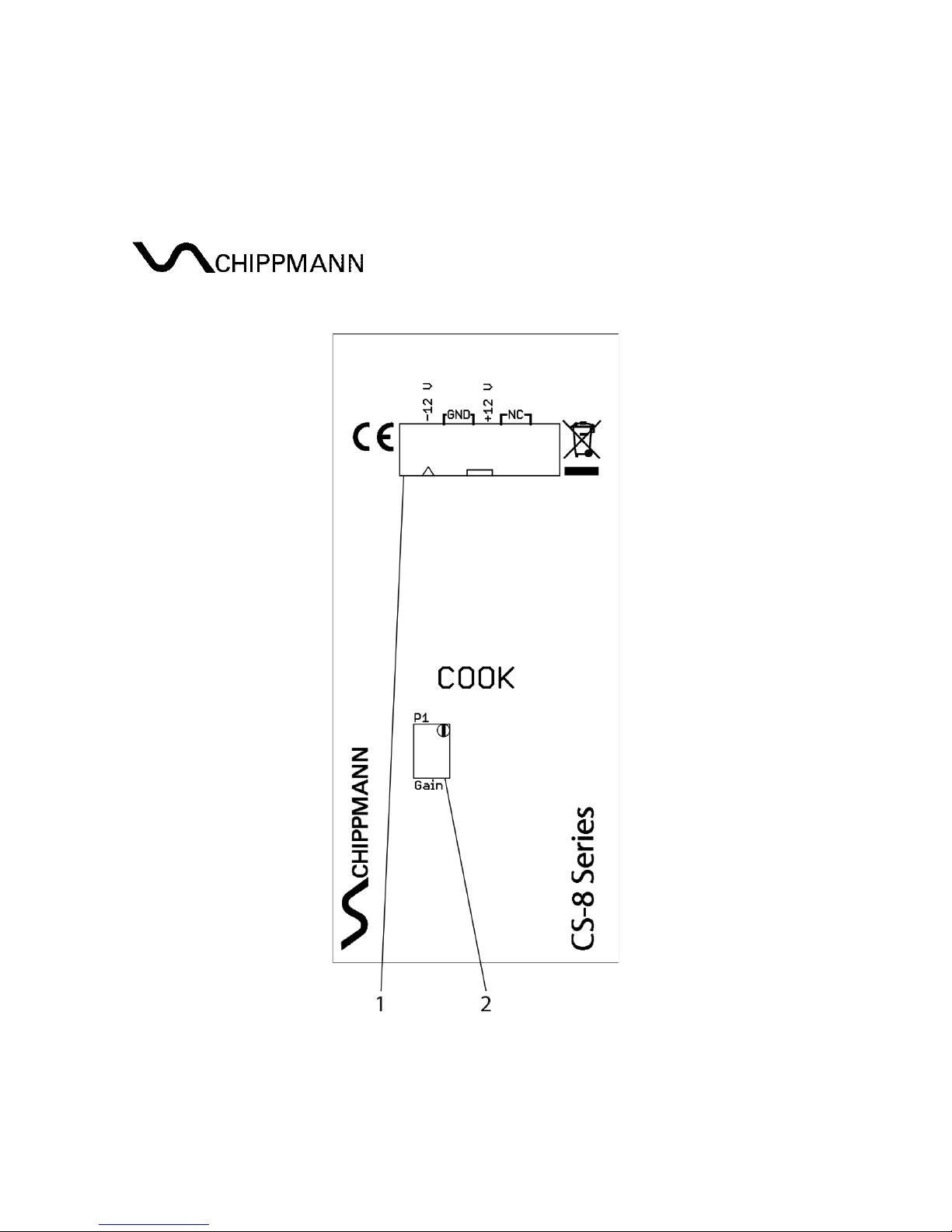
CS-8 Series COOK Rev1.3, Feb. 2019
-10-
Fig. 2 back
1. 16 Pin power supply box-header
2. P1 Gain 12-gauge-trimmer – adjusts output level at ig compression to
0 dbV (1 Vrms)
7.3 Initial operation
T e power connector’s (4) pin-out in top view (refer to fig. 2) is assigned as
follows:
Bottom to top, left to rig t. T us pin 1 is located at bottom left, pin 2 above pin
1 etc. Pin 15 is at bottom rig t, pin 16 at top rig t.

CS-8 Series COOK Rev1.3, Feb. 2019
-11-
Pin 1, 2 = -12 V (labelled wit a triangle)
Pin 3-8 = GND (ground, 0 V), located outward on all jacks
Pin 9, 10 = +12 V
Pin 11-16 = not in use
To ook up power to t e module, connect one of t e IDC-jacks of t e included
flat ribbon cable to t e connector (refer to fig. 2). Observe guide key for t e
polarity of t e connector in order to avoid pin reversal. T e red tag of t e
cable is to match the triangle-label.
8. MODULE DESCRIPTION
Structure
RMS-
Conv
OUT
Side C
(8)
IN
0.75
Response
(3)
Input
(6)
24 8
Input
(1)
VCA
Side C
(2)
A/R
Time
(4)
A/R Time
(9)
+5 V
T res/
Ratio
(7)
T /Rt
(5)
+5 V
Out
(10)
Fig. 3 Structure COOK
Fig. 3 s ows t e structure of t e compressor. T e VCA is t e audio processing
element. Depending on t e root-mean-square (RMS) of t e incoming audio

CS-8 Series COOK Rev1.3, Feb. 2019
-12-
and t e parameters
A/R Time
,
T res old/Ratio
and
Response
t e VCA is
controlled by t e RMS-converter, leading finally to dynamic compression.
Input
T is section includes t e jack 6 (Input) and t e controller 1 (Input). T e input
signal applied at
jack 6
is routed AC-coupled to
Cont. 1
w ere it get an
attenuation between 0 (-∞ db, full CCW) and 1 (0 db, full CW). To obtain a
signal gain of 1 (
Cont. 5
at full CCW) at t e signal output
Out
Cont. 1
as to be
set to full CW.
Ratio/Threshold/Make-up Gain
T is section includes t e controller 5 (Th/Rt) and t e jack 7 (Thres/Ratio). A
picture paints a t ousand words. Figure 4 s ows a family of curves for
corresponding input-to-output levels at rising Thres/Ratio values.
Fig. 4 T res old / Ratio

CS-8 Series COOK Rev1.3, Feb. 2019
-13-
At t e left side (at -100 dbV) one can see t e rising t e Make-up Gain. It is for
t e top grap 50 db (
Cont. 5
at full CW). T e point w ere a grap drops to a
lower slope is called T res old. In t e figure for eac curve it will be s ifted
from rig t ( ig input levels) to left (very low input levels), turning
Cont. 5
from left to rig t. T e softknee c aracter is maintained at any time, but cannot
fully evolve above 0 dbV (input) at low positions of
Cont. 5
. T e Ratio values
printed on t e front panel are taken at t e input level interval +10 dbV - 0 dbV
and serves t e orientation. T e scale values Th/Rt are valid for
Cont. 1
(input)
at full CW, ot erwise t e w ole grap ic will be s ifted to t e rig t, i.e. the
input level, which drives the compressor is crucial for the result!
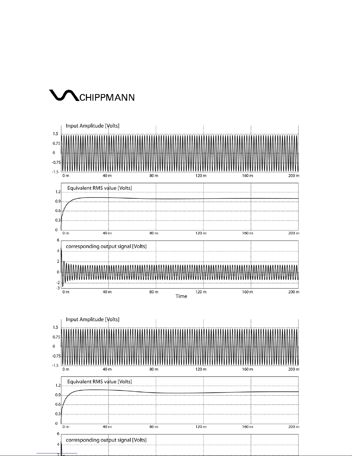
The RMS-Converter and Response
T e RMS-converter is always computing t e root-mean-square of t e
incoming audio and is so providing t e most important process variable for a
compressor. T e 4-position rotary s itch 3 (Response) selects an
overs ooting response of t e RMS-converter, especially at sudden level
c anges. T e eig t of t e overs oot increases wit ig er scale values. In
concrete terms t e 4 db value of t e
Response
scale means a total overs oot
(first peak - first valley) of 4 decibel. T is fact is reflected by t e corresponding
output signal. Figure 5a, 5b, 5c and 5d s ows t is be avior for all 4
Response
values.
Every grap ic is mapping t ree quantities. T e top grap always s ows an
incoming sinus signal of 500 Hz and an amplitude of 2.828 V, w ic equals a
root-mean-square of 1 Vrms. T e signal is sudden starting at T = 0 and t e
middle grap s ows ow t e RMS-converter forms wit in a certain time
(Attack) t e root-mean-square. T e bottom grap s ows t e corresponding
output signal, w ere a ig compression of about 10 is set. Wit rising
Response
values t e overs oots increases. For a compressor t e RMS-
converter controls t e VCA reverse. So, ig er RMS values (corresponding to
ig input levels) leading to a lower VCA gain and vice versa.
CS-8 Series COOK Rev1.3, Feb. 2019
-14-
Fig. 5a Response 0.75 db
Fig. 5b Response 2 db

CS-8 Series COOK Rev1.3, Feb. 2019
-15-
Fig. 5c Response 4 db
Fig. 5d Response 8 db

CS-8 Series COOK Rev1.3, Feb. 2019
-16-
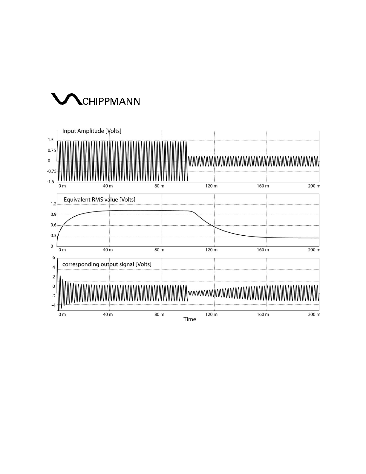
A/R Time
T e controller 4 (A/R Time) and t e jack 9 (Time) adjusts t e Attack- and
Release times of t e RMS-converter. Figure 6a s ows t e Attack p ase and t e
corresponding output signal. Because t e incoming level increase in t is
example is sudden and t e RMS-converter is applied wit a time constant,
namely t e Attack time, t e output firstly follows t e incoming level increase
before it will be reduced.
Fig. 6a Attack
Figure 6b s ows t e conversely case for a sudden incoming level decrease. As
above t e output firstly follows t is level reduction because of t e inertia of
t e RMS-converter by t e Release time. Because t is is an automatic
compressor t e Attack- and t e Release times are bounded toget er. The
Release time is for little and middle level jumps about 3 times, for large
and very large level jumps (extreme case: signal - no signal) about 8 times
larger than the Attack time.
CS-8 Series COOK Rev1.3, Feb. 2019
-17-
Fig. 6b Release
Side Chain
Jack 8 (Side Ch) as a switc ing contact, w ic is cutting (by plugging) t e
input signal at
jack 6
from t e RMS-converter. T e RMS-converter, now,
receives its AC-input signal, w ic root-mean-square it is computing to control
t e VCA from
jack 8
. Controller 2 (Side Chain) attenuates t e input signal at
jack 8
between 0 and 1. Even w en not using
jack 8
t e input signal (
jack 6
)
goes always via t e
controller 2
to t e RMS-converter input.
So, controller 2 has to be set to full CW for regular compressor operation!
Controller 2
in mid position, e.g., t e grap ic Fig. 4 would be s ifted by 6 db to
t e rig t and up!
Output
Jack 10 provides t e compressed output signal.

CS-8 Series COOK Rev1.3, Feb. 2019
-18-
9. TECHNICAL DATA AND SIGNAL VALUES
9.1 Technical Data (in general)
Input- and output-jacks: mono jack jacks 3.5 mm (1/8”)
Input jacks (except jack 8) ave grounded switc (0 V)
Power: -12 V / +12 V (polarity
protection)
Power consumption: typ. +35 mA/-45 mA (@ ±12 V)
Proper ambient temperature: 0 °C – +55 °C / 32F – 131F
Net weig t (module only): approx. 100 g / 0,22 lbs
Dimensions (W x H x D): 10 PU (50.5 mm) x
3 HU (128.5 mm) x 40 mm
Installation dept (be ind t e panel) <20 mm
9.2 Signals and ratings
Maximum input voltage at jacks (7, 9): ±10 V
Maximum input voltage at jacks (6, 8): ±20 V
Output noise:
Out (Make-up Gain = 0 db): 12 µVrms ≅ -98 dbV
Out (Make-up Gain = +30 db): 60 µVrms ≅ -84 dbV
Out (Make-up Gain = +50 db): 1.1 mVrms ≅ -59 dbV
Dynamic range: 120 db
Total Harmonic Distortion (THD max. @1 kHz, V
IN
= 1 V
rms
, Gain = 0db):
0.05 % (0.03 % typ.)
This manual suits for next models
1
Table of contents
Other Chippmann Music Equipment manuals


