Korg Pitchblack X Pro User manual

E 1
Ownerʼ
sManual
Table of Contents
Introduction .......................................................................................................2
Main Features .................................................................................................................................2
Controls ............................................................................................................................................2
Connections....................................................................................................................................3
Operation ...........................................................................................................5
Tuning procedure..........................................................................................................................5
Reference pitch settings .............................................................................................................5
Meter display setting ...................................................................................................................6
Meter display color settings ......................................................................................................7
Cable check function ...................................................................................................................7
Installing rack-mounting adapters ...................................................................8
Using rack-mounting adapters as a stand ............................................................................8
Specications .....................................................................................................9
* All product names and company names are the trademarks or registered trademarks of
their respective owners.

En-2
Introduction
ank you for purchasing the Korg Pitchblack X Pro Chromatic Tuner. To help you get the most out
of your new instrument, please read this manual carefully.
Main Features
• Ultra-high tuning accuracy of +/− 0.1 cents
• A newly developed ULTRA BUFFER keeps tone intact even through long cables and pedal boards
• “3D visual meter display” design oers wide viewing range and high visibility
• Selectable meter colors from 5 patterns
• Cable checker function
• Easily detachable Rack-angles - No screw driver needed!
Controls
1 2 3 4
5 9
6 7 8 10 1212 11
Guitar or bass
INPUT 1
OUTPUT1
To your effect
pedals or amps etc.
1. CALIB button
(→ “Reference pitch settings” on page 5)
2. DISPLAY button
(→ “Meter display setting” on page 6,
“Meter display color settings” on page 7)
3. Display
(→ “Tuning procedure” on page 5)
4. Meter Display
(→ “Meter display setting” on page 6)
5. POWER ON LED
(→ “Tuning procedure” on page 5)
6. CABLE CHECK LED
7. CABLE CHECK jack
(→ “Cable check function” on page 7)
8. OUTPUT1 jack
9. MUTE button, LED
(→ “OUTPUT1, 2 jacks” on page 3)
10. INPUT1 jack
11. STANDBY/ON button
(→ “Tuning procedure” on page 5)
12. Rack-mounting adapter
(→ “Installing rack-mounting adapters” on
page 8)

En-3
Connections
To effect pedals, amps or other equipment
Guitar, bass, etc.
Guitar, bass, etc.
To effect pedals, amps or other equipment
AC adapter (included)
To AC outlet
INPUT 2
DC 9V
OUTPUT2
INPUT 1OUTPUT1
Turn o the power to all devices before you connect an instrument to avoid damaging your equip-
ment.
e INPUT1, INPUT2, OUTPUT1, OUTPUT2 and CABLE CHECK jacks are for mono signals
only. Stereo (TRS) cables will not work.
INPUT1 jack
Connect a cable from the INPUT1 jack to the instrument to be tuned.
INPUT2 jack
Connect a cable from the INPUT2 jack to the instrument to be tuned. If a cable is connected to the
INPUT1 jack on the front panel, this jack will be disabled and cannot be used.
OUTPUT1, 2 jacks
Connect a cable from the OUTPUT jack to your eect pedals, amp, etc.
e signals that are input from either the INPUT1 or the INPUT2 jack pass through the buer and
are respectively sent to the OUTPUT1 and OUTPUT2 jacks.
Press the MUTE button to enable or disable the mute function for the signal that’s output from the
OUTPUT1 and OUTPUT2 jacks. When the mute function is enabled, the MUTE LED will light up,
and the signal will not be output from the OUTPUT1 and OUTPUT2 jacks.
NOTE: When the tuner is in standby power mode, no signal is output from the OUTPUT1 and
OUTPUT2 jacks.

En-4
CABLE CHECK jack
Connect one end of a standard mono instrument cable to the INPUT1 jack and the other end to the
CABLE CHECK jack.
NOTE: Noise may occur if a cable is connected to the CABLE CHECK jack aer a cable was connected
to the INPUT1 jack.
DC 9 V jack
Connect the included AC adapter to this jack.
Never use any AC adapter other than the one that’s included. is may cause a malfunction.
Fasten the AC adapter’s power cord in place by hooking it on the cord hook to prevent the included
AC adapter’s plug from being disconnected from the terminal.
Cord hook

En-5
Operation
Tuning procedure
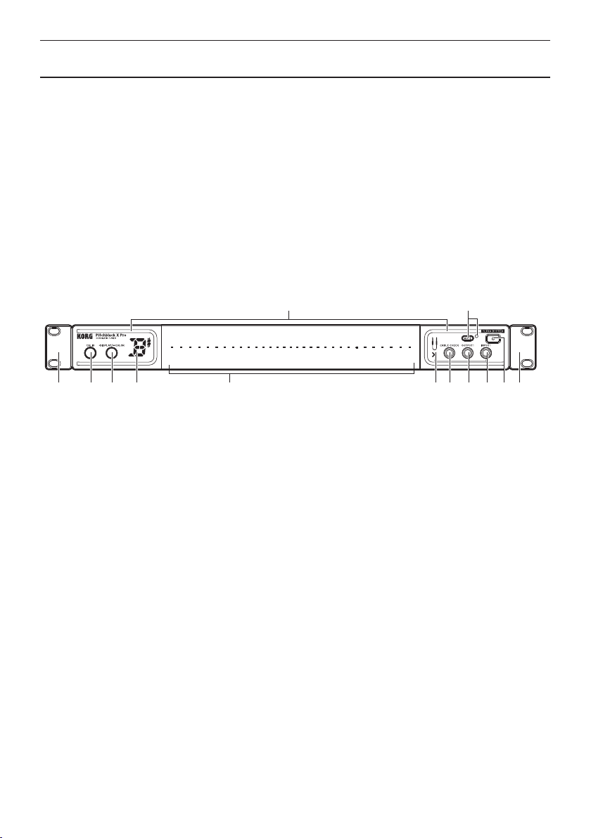
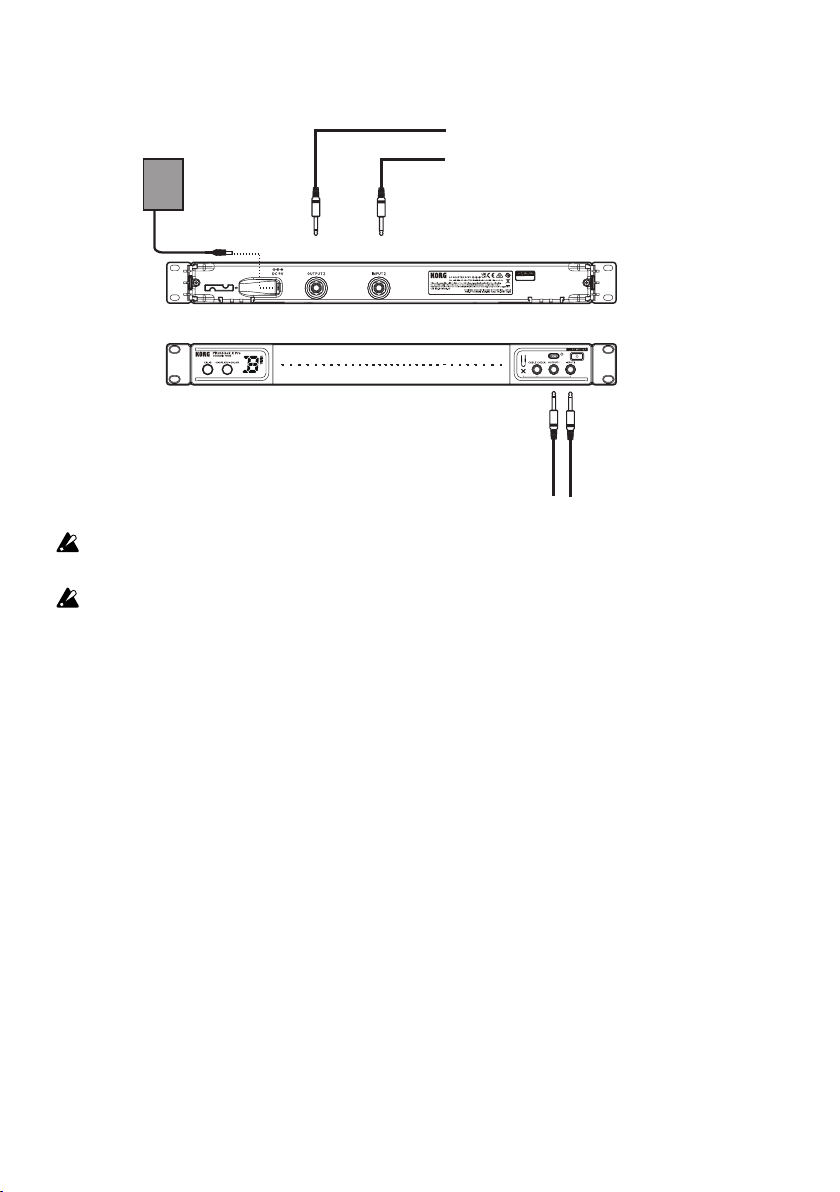
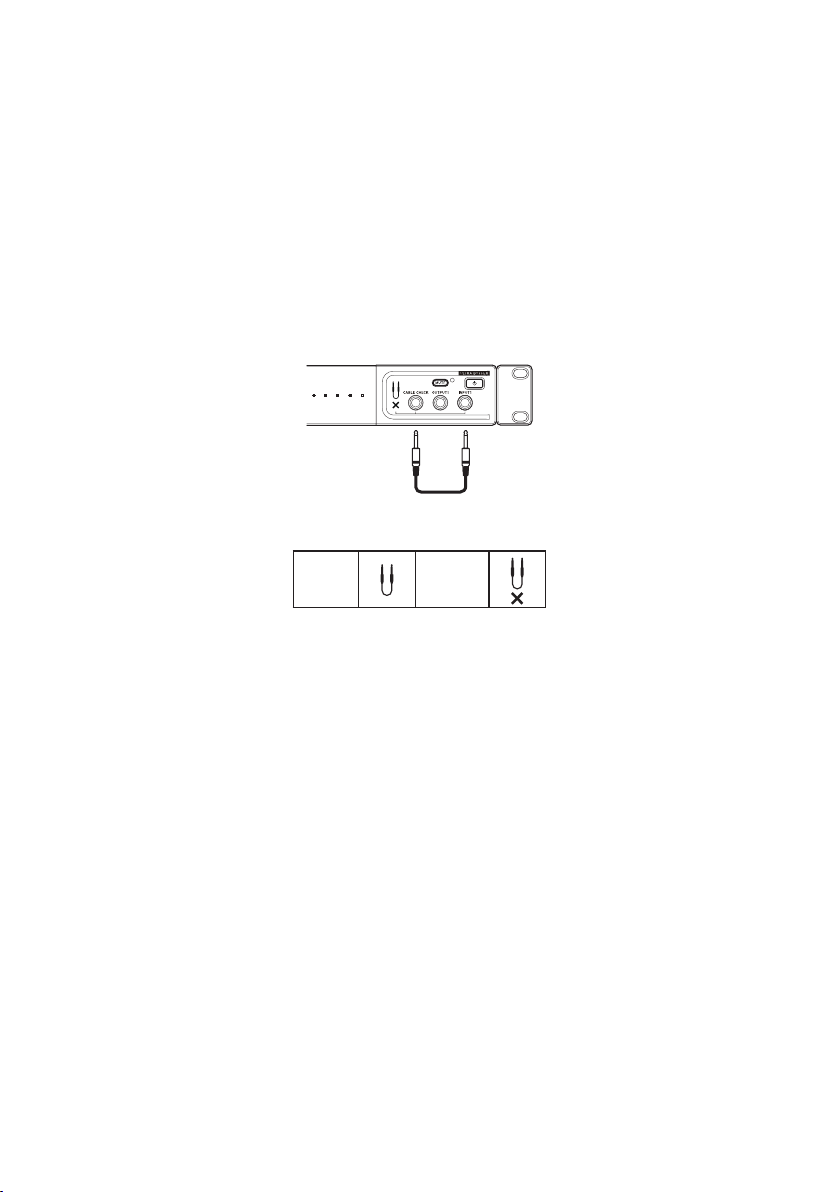
1. Connect the instrument to be tuned to the INPUT1 jack or to the INPUT2 jack.
NOTE: If a plug is connected to the INPUT1 jack on the front panel, the INPUT2 jack on the rear
panel will be disabled and cannot be used.
2. Press the STANDBY/ON button to turn on the tuner.
e POWER ON LED will light up, and the calibration setting (0–9) will ash in the note display
for a few seconds.
NOTE: If there is no user input for up to 4 hours, the auto power-o function will automatically
put the tuner in the standby power mode. Holding down the MUTE button and pressing
the STANDBY/ON button while the tuner is turned on will disable the auto power-o
function.
3. Set the calibration, meter display and display color as necessary.
(→“Reference pitch settings” on page 5, “Meter display setting” on page 6, “Meter display
color settings” on page 7).
4. Play a single note on your instrument.
5. Tune while watching the meter display. e note display will indicate the note name that is closest
to the pitch you input.
Reference pitch settings
Set the reference pitch for tuning (the A note in the middle of the piano keyboard = A4).
e default setting is “0: 440 Hz”.
1. Press the CALIB button.
e current setting is shown for several seconds on the display (lit → blinking).
2. While the current setting is shown, press the CALIB button to set the reference pitch.
Each time you press the CALIB button you will cycle through the following settings.
0: 440 Hz, 1: 441 Hz, 2: 442 Hz, 3: 443 Hz, 4: 444 Hz,
5: 445 Hz, 6: 436 Hz, 7: 437 Hz, 8: 438 Hz, 9: 439 Hz
3. When you’ve chosen the desired setting, wait for two seconds without pressing any buttons.
e new setting will blink in the note name display indicating that the reference pitch has been
set, and you can now use the tuner normally.

En-6
Meter display setting
You can specify the display pattern that’s shown on the meter’s display. You can choose one of four dis-
play patterns.
e default setting is “1: Regular meter”.
1. Press the DISPLAY button.
e current setting is shown for several seconds on the display (lit → blinking).
2. While this setting is shown, press the DISPLAY button to select the desired display pattern.
e setting will change each time you press the button.
1: Regular meter
Tune your instrument so that the center LED of the meter display is lit up.
e LED illumination will move from the center toward the right if the note is sharp, or from the
center toward the le if the note is at.
2: Strobe meter
Tune your instrument so that the illumination stops owing in the meter display. e illumination
will ow from le to right if the note is sharp, or from right to le if the note is at.
3: Half-strobe meter
Tune your instrument so that the stream stops and only the center LED is lit up. e right side of
the meter display will strobe if the note is sharp, and the le side of the meter display will strobe if
the note is at. When the pitch is correct, only the center LED will light up.
4. Focus meter
is mode enlarges the meter display within a ±10 cent range, for even more precise tuning.
Tune your instrument so that the center LED of the meter display is lit up.
When the tuning of the inputted note is within ±10 cents, the POWER ON LED changes to red
and the meter changes color. Also, the meter view enlarges to show the ±10 cent range.
e meter returns to the regular display when the tuning falls outside of the ±10 cent range.
3. When you’ve chosen the desired setting, wait for two seconds without pressing any buttons.
e display indication will blink several times, and the meter display setting will be made. e
tuner will then return to its normal state, allowing you to tune.

En-7
Meter display color settings
You can specify the color of the meter display. ere are ve color combinations to choose from.
1. Long-press the DISPLAY button.
e POWER ON LED will blink, and the color number appears in the note display.
2. While the POWER ON LED is blinking, press the DISPLAY button to select the color.
3. Once you’ve made the setting, wait for about two seconds without pressing any buttons.
e meter display color setting will be made, and you can now use the tuner normally.
Cable check function
When the cable is connected, the cable check function will start and the results will be shown on the
CABLE CHECK LEDs.
CABLE CHECK INPUT 1
Normal: Abnormal:
NOTE: Cable checking can only be done with mono cables. Stereo cables cannot be checked.

En-8
Installing rack-mounting adapters
By installing the included rack-mounting adapters, the tuner can be attached to an EIA standard rack
or case, etc., with the appropriate rack screws.
NOTE: ere is no dierence between the le and right rack-mounting adapters.
Installation
Align the rack-mounting adapters with the mounting slots on the
tuner, and then slide in the adapters from the back. Securely install
the adapters so that they lock into place and will not slip out.
If the tuner is attached to the rack without suciently installing
the adapters, the tuner may fall and become damaged.
Removal
Release the lock on the back of the tuner, and then slide out the adapter to
remove it.
Rack-mounting holes
Use these holes to attach the tuner to an EIA standard rack or case with the
included screws.
Using rack-mounting adapters as a stand
By installing the rack-mounting adapters in the mounting slots on the bottom of the tuner, it can be
positioned at an easy-to-read angle when it is placed on a table.

En-9
Specications
Tuning: 12-note equal temperament
Detection range: E0 (20.60 Hz)–C8 (4186 Hz), sine wave
Reference pitch: A4 = 436–445 Hz (1 Hz steps)
Detection accuracy: ±0.1 cent
Input impedance: 1 MΩ (when tuner is on)
Connects: Front: INPUT1 jack (1/4″/6.3 mm monaural phone jack), OUTPUT1 jack
(1/4″/6.3 mm monaural phone jack), CABLE CHECK jack (1/4″/6.3 mm
monaural phone jack)
Rear: INPUT2 jack (1/4″/6.3 mm monaural phone jack), OUTPUT2 jack
(1/4″/6.3 mm monaural phone jack), DC 9 V jack
Power supply: 9V ACadapter
Dimensions (W × D × H):
430 mm × 50 mm × 44 mm (16.93″× 1.97″× 1.73″); tuner only, including
extensions
With rack-mounting adapters:
482 mm × 50 mm × 44 mm (18.98″× 1.97″× 1.73″); including extensions
Weig ht: Tuner only: 379 g / 13.37 oz.
Included items: Customer Notice (Dear Customer), Precautions, AC adapter,
Screws × 4, washers × 4, Rack-mounting adapter × 2
* Appearance and specications are subject to change without notice for improvement.

F 1
Manueldʼ
utilisation
Sommaire
Introduction .......................................................................................................2
Principales fonctions....................................................................................................................2
Commandes....................................................................................................................................2
Connexions .....................................................................................................................................3
Fonctionnement ................................................................................................5
Accordage........................................................................................................................................5
Réglages de hauteur de référence ..........................................................................................5
Mode d’achage de l’accordeur .............................................................................................6
Réglages de couleur d’achage de l’accordeur .................................................................7
Prise pour test de câble (CABLE CHECK)................................................................................7
Installation des adaptateurs de montage en rack ...........................................8
Utilisation des adaptateurs de montage en rack comme pied......................................8
Fiche technique..................................................................................................9
* Tous les noms de produits et de sociétés sont des marques commerciales ou déposées
de leur détenteur respectif.

Fr-2
Introduction
Nous vous remercions d’avoir choisi l’accordeur chromatique Pitchblack X Pro de Korg. An de
pouvoir exploiter au mieux toutes les possibilités oertes par l’instrument, veuillez lire attentivement
ce manuel.
Principales fonctions
• Précision de justesse ultra élevée de +/− 0,1 cents
• Le nouvel ULTRA BUFFER récemment développé assure de conserver le son intact même avec de
longs câbles et des Pedal Boards
• “Acheur vumètre 3D” ore un large angle de vue et une excellente visibilité
• Choix des couleurs du vumètre selon 5 motifs
• Fonction testeur de câble
• Pattes de rack facilement détachables – pas de tournevis nécessaire.
Commandes
1 2 3 4
5 9
6 7 8 10 1212 11
Guitar or bass
INPUT 1
OUTPUT1
To your effect
pedals or amps etc.
1. Bouton CALIB
(→ “Réglages de hauteur de référence” à la
page 5)
2. Bouton DISPLAY
(→ “Mode d’achage de l’accordeur” à la
page 6, “Réglages de couleur d’achage
de l’accordeur” à la page 7)
3. Ecran
(→ “Accordage” à la page 5)
4. Achage d’accordage
(→ “Mode d’achage de l’accordeur” à la
page 6)
5. Témoin POWER ON
(→ “Accordage” à la page 5)
6. Témoin CABLE CHECK
7. Prise CABLE CHECK
(→ “Prise pour test de câble (CABLE
CHECK)” à la page 7)
8. Prise OUTPUT1
9. Bouton MUTE, Témoin MUTE
(→ “Prises OUTPUT1, 2” à la page 3)
10. Prise INPUT1
11. Bouton STANDBY/ON
(→ “Accordage” à la page 5)
12. Adaptateur de montage en rack
(→ “Installation des adaptateurs de montage
en rack” à la page 8)

Fr-3
Connexions
Vers des pédales d’effet, des amplis ou d’autres dispositifs
Guitare, basse, etc.
Vers des pédales d’effet, des amplis ou d’autres dispositifs
Adaptateur secteur (fourni)
Vers une prise de courant
INPUT 2
DC 9V
OUTPUT2
INPUT 1OUTPUT1
Avant de brancher un instrument, mettez tous les dispositifs hors tension pour éviter d’endomma-
ger votre matériel.
Les prises INPUT1, INPUT2, OUTPUT1, OUTPUT2 et CABLE CHECK sont uniquement
destinées à des signaux mono. N’utilisez pas de câbles stéréo (TRS).
Prise INPUT1
Raccordez un câble de votre instrument à la prise INPUT1 de l’accordeur.
Prise INPUT2
Raccordez un câble de votre instrument à la prise INPUT2 de l’accordeur. Quand un câble est raccor-
dé à la prise INPUT1 du panneau avant, cette prise est désactivée et inutilisable.
Prises OUTPUT1, 2
Raccordez un câble de la prise OUTPUT à vos pédales d’eet ou amplis, etc.
Les signaux reçus à la prise INPUT1 ou à la prise INPUT2 transitent par le tampon et sont envoyés
respectivement aux prises OUTPUT1 et OUTPUT2.
Appuyez sur le bouton MUTE pour activer ou désactiver la fonction de coupure (Mute) du signal
transmis aux prises OUTPUT1 et OUTPUT2. Quand la fonction Mute est active, le témoin MUTE
s’allume et le signal cesse d’être transmis aux prises OUTPUT1 et OUTPUT2.
REMARQUE: Quand l’accordeur se trouve en mode de veille, aucun signal n’est transmis aux prises OUT-
PUT1 et OUTPUT2.

Fr-4
Prise CABLE CHECK
Branchez l’extrémité d’un câble mono standard pour instrument à la prise INPUT1 et l’autre extrémité
du câble à la prise CABLE CHECK.
REMARQUE: Du bruit peut survenir si un câble est branché à une prise CABLE CHECK alors qu’un
câble a été branché à la prise INPUT1.
Prise DC 9V
Branchez l’adaptateur secteur fourni à cette prise.
N’utilisez jamais d’autre adaptateur secteur que l’adaptateur fourni. Cela pourrait causer des
dysfonctionnements.
Fixez le cordon d’alimentation de l’adaptateur secteur en l’enroulant autour du crochet prévu à cet eet
an d’éviter que la che de l’adaptateur secteur fourni ne soit accidentellement débranchée de sa prise.
Crochet pour cordon

Fr-5
Fonctionnement
Accordage
1. Branchez l’instrument à accorder à la prise INPUT1 ou à la prise INPUT2.
REMARQUE: Quand un câble est raccordé à la prise INPUT1 du panneau avant, la prise INPUT2 du
panneau arrière est désactivée et inutilisable.
2. Appuyez sur le bouton STANDBY/ON pour mettre l’accordeur sous tension.
Le témoin POWER ON s’allume et le réglage de calibrage (0–9) clignote sur l’achage de note
pendant quelques secondes.
REMARQUE: Si l’accordeur ne reçoit aucun signal ou si aucune manipulation n’est faite pendant 4
heures, la fonction de coupure automatique d’alimentation met l’accordeur en mode de
veille. Vous pouvez désactiver la fonction de coupure automatique d’alimentation en
maintenant enfoncé le bouton MUTE et en appuyant sur le bouton STANDBY/ON
quand l’accordeur est sous tension.
3. Eectuez les réglages voulus de calibrage, de mode et de couleur d’achage.
(→“Réglages de hauteur de référence” à la page 5, “Mode d’achage de l’accordeur” à la page
6, “Réglages de couleur d’achage de l’accordeur” à la page 7).
4. Jouez une note isolée sur votre instrument.
5. Accordez l’instrument en regardant l’achage d’accordage. L’achage de note indique le nom de la
note dont la hauteur se rapproche le plus de celle de la note jouée.
Réglages de hauteur de référence
Réglez la hauteur de référence pour l’accordage (la note A au centre du clavier d’un piano correspond
à A4).
Par défaut, ce paramètre est réglé sur “0 : 440 Hz”.
1. Appuyez sur le bouton “CALIB”.
Le réglage en vigueur est aché quelques secondes (allumé → clignotant).
2. Pendant que le réglage courant est aché à l’écran, appuyez sur le bouton CALIB pour régler la
hauteur de référence.
Chaque pression sur le bouton CALIB sélectionne successivement les réglages suivants.
0 : 440 Hz, 1 : 441 Hz, 2 : 442 Hz, 3 : 443 Hz, 4 : 444 Hz,
5 : 445 Hz, 6 : 436 Hz, 7 : 437 Hz, 8 : 438 Hz, 9 : 439 Hz
3. Quand vous avez choisi un réglage, attendez environ deux secondes sans appuyer sur le moindre
bouton.
Le nouveau réglage clignote sur l’achage du nom de la note, indiquant que la hauteur de réfé-
rence est réglée et que vous pouvez utiliser l’accordeur normalement.

Fr-6
Mode d’achage de l’accordeur
Vous pouvez choisir la façon dont l’achage représente l’accordage. Vous pouvez choisir parmi 4
modes d’achage.
Par défaut, ce paramètre est réglé sur “1 : achage normal”.
1. Appuyez sur le bouton DISPLAY.
Le réglage en vigueur est aché quelques secondes (allumé → clignotant).
2. Tant que le réglage est aché, appuyez sur le bouton DISPLAY pour sélectionner un mode
d’achage.
Chaque pression sur le bouton change l’achage.
1 : Achage traditionnel
L’instrument est accordé quand la diode centrale est allumée.
L’éclairage des diodes passe du centre vers la droite si la note est trop haute ou du centre vers la
gauche si la note est trop basse.
2 : Achage stroboscopique
Accordez l’instrument jusqu’à ce que l’éclairage des diodes cesse de se déplacer. Si la note est trop
haute, l’éclairage des diodes se déplace de gauche à droite et si la note est trop basse, il se déplace
de droite à gauche.
3 : Achage semi-stroboscopique
L’ instrument est accordé quand le ux cesse et la diode centrale est allumée. Les diodes de la
moitié droite s’allument successivement si la note est trop haute et celles de la moitié gauche
s’allument si la note est trop basse. Quand la note est juste, seule la diode centrale est allumée.
4. Achage focal
Ce mode agrandit l’achage sur une plage de ±10 cents, pour une grande précision d’accord.
L’instrument est accordé quand la diode centrale est allumée.
Quand la hauteur de la note jouée se situe à ±10 cents, la couleur de la diode POWER ON change
en rouge et la couleur d’achage change. En outre, l’achage s’agrandit en se focalisant sur la
plage de ±10 cents.
L’accordeur réactive son achage normal quand la hauteur de la note jouée sort de la plage ±10
cents.
3. Quand vous avez choisi un réglage, attendez environ deux secondes sans appuyer sur le moindre
bouton.
L’indication à l’écran clignote plusieurs fois et le mode d’achage choisi entre en vigueur. L’accor-
deur revient en mode de fonctionnement normal, permettant d’accorder l’instrument.

Fr-7
Réglages de couleur d’achage de l’accordeur
Vous pouvez choisir la couleur d’achage de l’accordeur. Vous pouvez choisir parmi cinq combinai-
sons de couleurs.
1. Appliquez une longue pression sur le bouton DISPLAY.
La diode POWER ON clignote et le numéro de la couleur s’ache sur l’achage du nom de la
note.
2. Quand la diode POWER ON clignote, sélectionnez la couleur en appuyant sur le bouton DIS-
PLAY.
3. Quand vous avez eectué le réglage, attendez environ deux secondes sans appuyer sur le moindre
bouton.
Le réglage de couleur d’achage est exécuté, après quoi vous pouvez utiliser normalement
l’accordeur.
Prise pour test de câble (CABLE CHECK)
Branchez une che d’un câble mono traditionnel à la prise INPUT et son autre che à la prise CABLE
CHECK.Quand vous branchez le câble, la fonction de test vérie le câble et ache le résultat avec une
témoin CABLE CHECK.
CABLE CHECK INPUT 1
Câble
correct :
Câble
défectueux :
REMARQUE: La fonction de test de câble est uniquement disponible pour des câbles mono. Les câbles
stéréo ne peuvent donc pas être testés.

Fr-8
Installation des adaptateurs de montage en rack
Les adaptateurs de montage en rack fournis permettent d’intégrer l’accordeur à un rack ou boîtier
standard (norme EIA) et de le xer avec des vis de montage en rack.
REMARQUE: Les deux adaptateurs de montage en rack fournis sont totalement identiques.
Installation
Alignez les adaptateurs de montage en rack sur les glissières de
montage de l’accordeur, puis glissez les adaptateurs depuis l’arrière
de l’accordeur. Veillez à ce que les adaptateurs soient correctement
installés et ne bougent pas.
Si les adaptateurs de montage ne sont pas correctement instal-
lés, l’accordeur risque de se détacher du rack, de tomber et
d’être endommagé.
Dépose
Libérez le verrouillage au dos de l’accordeur et glissez l’adaptateur de
montage vers l’arrière de l’accordeur.
Orices pour le montage en rack
Utilisez ces orices pour xer l’accordeur sur un rack ou boîtier standard
EIA avec les vis fournies.
Utilisation des adaptateurs de montage en rack comme
pied
Vous pouvez aussi installer les adaptateurs de montage en rack sur les glissières de montage au dessous
de l’accordeur an de vous en servir comme pied. Cela permet de poser l’accordeur sur table en
bénéciant d’une bonne lisibilité de l’achage.

Fr-9
Fiche technique
Gamme : Tempérament égal (12 intervalles chromatiques)
Plage de détection : E0 (20,60 Hz)~C8 (4186 Hz), onde sinus
Hauteur de référence : A4= 436~445 Hz (par pas de 1 Hz)
Précision de la détection : ±0,1 cent
Impédance d’entrée : 1 MΩ (quand l’accordeur est sous tension)
Prises: Panneau avant: prise INPUT1 (prise jack mono de 1/4″/6,3 mm), prise
OUTPUT1 (prise jack mono de 1/4″/6,3 mm), prise CABLE CHECK (prise
jack mono de 1/4″/6,3 mm)
Panneau arrière: prise INPUT2 (prise jack mono de 1/4″/6,3 mm), prise
OUTPUT2 (prise jack mono de 1/4″/6,3 mm), prise DC 9 V
Alimentation : Adaptateur secteur 9VCA
Dimensions (L × P× H) :
430 mm × 50 mm × 44 mm; accordeur uniquement, pieds en caoutchouc
compris
Avec les adaptateurs de montage en rack:
482 mm × 50 mm × 44 mm (pieds en caoutchouc compris)
Poids : Accordeur seul : 379 g
Accessoires fournis : Avis au client (Cher client), Précautions, adaptateur secteur,
vis × 4, rondelle × 4, adaptateur de montage en rack × 2
* Les caractéristiques et l’aspect du produit sont susceptibles d’être modiés sans préavis en vue d’une
amélioration.

G 1
Bedienungsanleitung
Inhalt
Einleitung ...........................................................................................................2
Die wichtigsten Funktionen.......................................................................................................2
Bedienelemente ............................................................................................................................2
Anschlüsse.......................................................................................................................................3
Betrieb ................................................................................................................5
Stimmvorgang ...............................................................................................................................5
Einstellen der Referenztonhöhe...............................................................................................5
Einstellung der Stimmanzeige..................................................................................................6
Einstellung des Farbschemas der Stimmanzeige ...............................................................7
CABLE CHECK-Buchse..................................................................................................................7
Anbringen der Rack-Montageadapter .............................................................8
Verwendung der Rack-Montageadapter als Ständer........................................................8
Technische Daten...............................................................................................9
* Alle Produkt- und Firmennamen sind Warenzeichen oder eingetragene Warenzeichen
der betreenden Eigentümer.
This manual suits for next models
1
Table of contents
Languages:
Other Korg Music Equipment manuals