CHISAGE Mars-12G1-LE User manual


Mars-12G1-LE
Hybrid Inverter
Technical 、Installation and user manuals

Content
About the manual........................................................................................................... 1
Introduction to security.................................................................................................. 1
1 Overview..................................................................................................................... 2
1.1 Product Overview.............................................................................................2
1.2 Product Brief Introduction................................................................................2
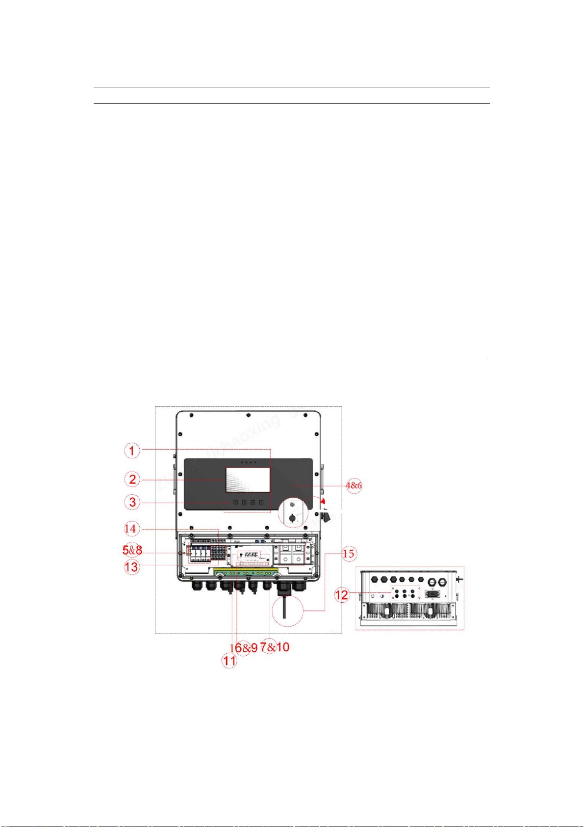
1.2.1 Appearance............................................................................................ 2
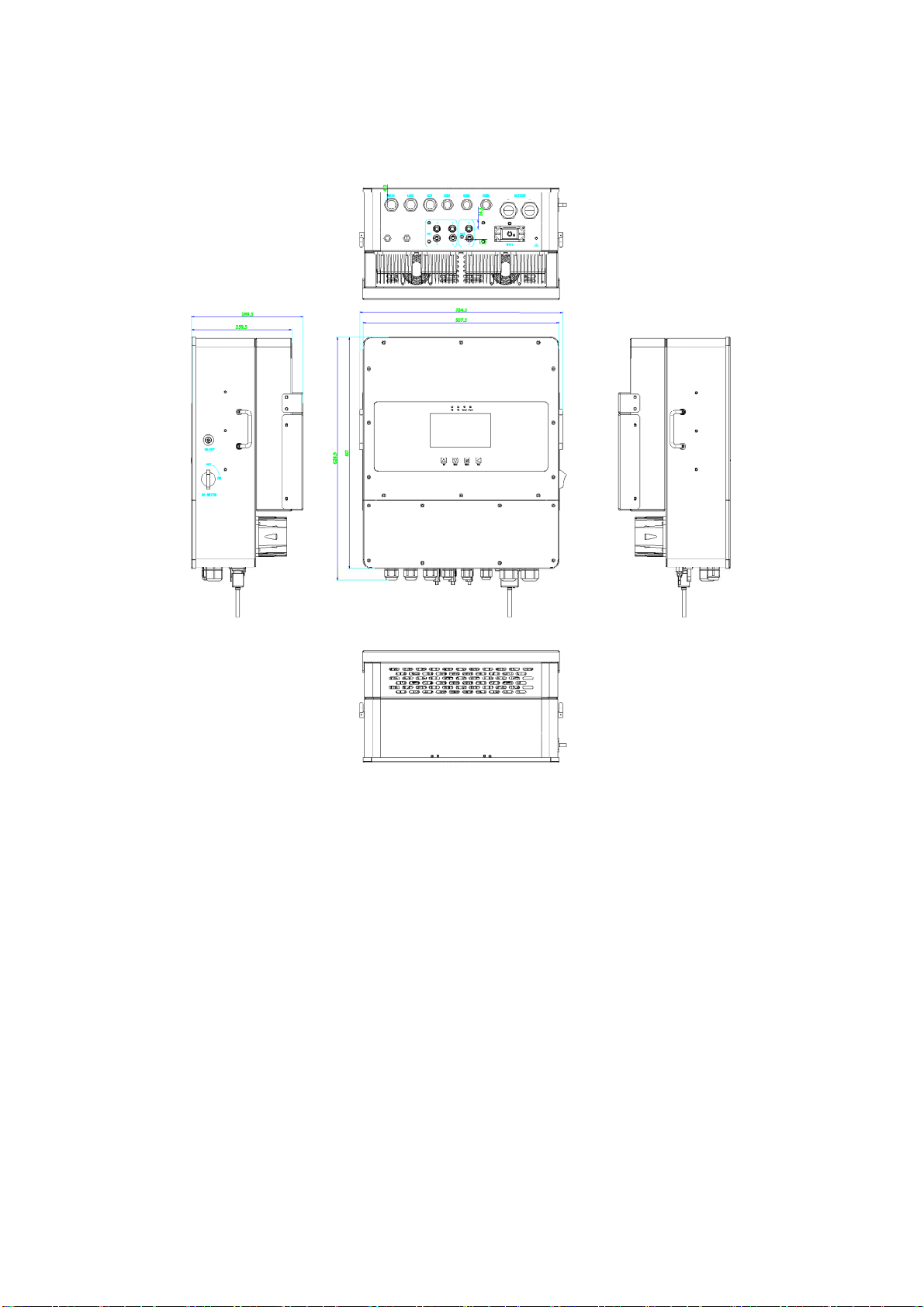
1.2.2 Product Structure, Si e, Weight.............................................................4
1.3 Product Features (main functions and benefits)...............................................5
1.3.1 Control Function....................................................................................6
1.3.2 Protection Function............................................................................... 6
1.3.3 Performance Characteristics..................................................................6
1.4 System Architecture Characteristics.................................................................7
2 Product Technical Description.................................................................................... 9
2.1 Relevant Standards........................................................................................... 9
2.1.1 Grid Connection Specification.............................................................. 9
2.1.2 EMC and Safety Standards....................................................................9
2.2 Electrical Performance................................................................................... 10
2.2.1 Technical Specifications......................................................................10
2.2.2 Electrical Interference Performance.................................................... 11
2.2.3 Insulation Performance........................................................................11
2.2.4 Mechanical Properties......................................................................... 12
3 Installation.................................................................................................................13
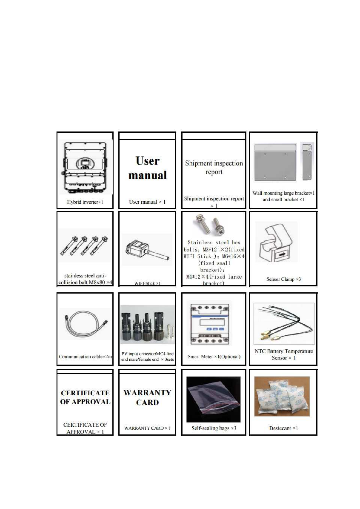
3.1 Product List Details........................................................................................13
3.2 Installation Environment................................................................................ 15
3.3 Installation Instructions.................................................................................. 15
3.4 Installation Of Equipment Body.....................................................................17
3.5 Connecting Devices To Other Systems.......................................................... 18
3.5.1 Terminal Introduction..........................................................................18
3.5.2 Battery connection...............................................................................21
3.5.3 Grid, generator and load connection................................................... 22

3.5.4 Photovoltaic connection...................................................................... 23
3.5.5 CT connection..................................................................................... 26
3.5.6 Ground connection (mandatory)......................................................... 27
3.5.7 WIFI Connection.................................................................................27
3.5.8 Equipment System Wiring...................................................................28
4 LCD Operating Instructions...................................................................................... 29
4.1 Interface Description...................................................................................... 29
4.1.1 Main interface description...................................................................29
4.1.2 Setting Instructions..............................................................................31
4.1.3 History Information Interface..............................................................36
4.1.4 Device Information Interface.............................................................. 36
4.2 Operation Instructions.................................................................................... 37
5 Fault Handling...........................................................................................................38
6 Limitation Of Liability.............................................................................................. 38
Appendix...................................................................................................................... 39
BMS Network Interface Definition Description.................................................. 39
Instrument Transformer Si e And Model.............................................................40

1
About the manual
This manual focuses on product information, functional operation 、device
installation and maintenance guides. This brochure does not cover all information
related to PV.
How to use:
Before installing and debugging this inverter, please be sure to read the
installation manual and other relevant materials carefully, and the information must be
properly stored for subsequent use.
The content may be updated or revised periodically due to product development.
The contents of this manual are subject to change without notice. The latest brochure
is available on request from your dealer.
Introduction to security
This chapter contains important safety and operating instructions, read and save this
manual for future reference.
Please read the instruction manual carefully before using this product;
Do not disassemble this machine by non-professionals, incorrect reassembly may
cause electric shock or fire. If you need maintenance or repair, please contact the
after-sales service center;
For your safety, disconnect all power and cables from this appliance before
maintenance or cleaning;
Note: Non-professionals should not install this device and battery.
In order to ensure the best working condition of this equipment, please choose the
appropriate cable si e correctly;
Metal tools should be avoided near the battery as much as possible, and caution
should be exercised if necessary, as dropping tools may cause sparks or short
circuits in the battery or other electrical components, or even cause an explosion.
When disconnecting AC or DC terminals, follow the installation steps exactly,
refer to the Installation section of this manual for details.
Grounding Instructions - This device should be connected to a permanently
grounded wiring system. Be sure to follow local requirements and regulations to
install this device.
Do not short-circuit the AC output and DC input, and do not connect the mains
power when shorted.

2
1 Overview
1.1 Product Overview
This product (hybrid inverter: photovoltaic energy storage integrated energy
conversion device, a device used in photovoltaic, energy storage combined power
generation system to achieve DC / AC power conversion), using power electronic
control technology, can coordinate the control of photovoltaic and energy storage
battery output, smooth the power fluctuation of photovoltaic cells, through the energy
storage conversion technology, output AC power that meets the requirements of the
standard and supply power to the load.
The equipment has functions and features such as dynamic adjustment of
working mode, off-grid mode switching, photovoltaic energy power tracking, and fine
management of energy storage batteries. Using photovoltaic and energy storage
through DC/DC common DC bus collection, flexible control, high stability, not only
can reali e photovoltaic MPPT control, but also can adapt to different types of energy
storage, give full play to the adjustment range of energy storage, optimi e the charge
and discharge control of energy storage, and improve the utili ation rate of energy. Its
comprehensive LCD display provides user-configurable and easily accessible button
operations such as battery charging, AC/solar charging, and acceptable input voltages
based on different applications.
1.2 Product Brief Introduction
1.2.1 Appearance
The appearance of this product and its various descriptions are shown in Figure 1.1
and Table 1.1 below

Table 1.1 Description of definitions in various parts of the product Number Definition Description
Number Definition Explain
1 Pilot lamp
2 LCD display
3 Function button
4 Battery black start button
5 Grid switch
6 DC switch
7 Electricity meter-485 interface
8 Battery input interface
9 Functional interface
10 ModBUS interface
11 BMS interface
12 PV input interface with 2 MPPT
13 Load interface
14 Oil turbine interface
15 WIFI interface
16 CT interface
Figure 1.1 Overview of the appearance of hybrid inverter

4
1.2.2 Product Structure, Size, Weight
Three-dimensional diagram

5
Plan
Si e(W*H*D)(mm):460x640x280。
Weight(kg):45。
1.3 Product Features (main functions and benefits)
The company's hybrid inverter adopts advanced digital control technology,
optimi es the control performance and improves the reliability of the system, suitable
for different frequency power grids and different battery charging and discharging
needs, and has a modular design on the structure to facilitate installation and
maintenance. Its main performance characteristics are as follows:

6
1. .1 Control Function
Constant power charge/discharge
Keep voltage constant and limit current
Reactive power regulation
Off-grid constant voltage and constant frequency
Parallel/off-grid smooth switching
Low voltage fault ride-through
Power point tracking
Multi-machine parallel operation
Track grid plan online
Smooth distributed photovoltaic output fluctuation
External environment adaptive
1. .2 Protection Function
Detection PV input lightning
PV input lightning protection
Anti-islanding protection
PV port/energy storage port polarity reverse polarity protection
PV port/energy storage port overvoltage/current graded protection
Net-side over/undervoltage graded protection
Net-side overcurrent/undercurrent graded protection
Net-side over/under-frequency protection
Output short circuit protection
IGBT module overcurrent protection
IGBT module/transformer/reactor over-temperature protection
Battery charge/discharge protection
1. . Performance Characteristics
Strong overload capacity, 110% overload can run for 2h, 120% can run for 2min;
Support completely unbalanced load;

7
The system has strong scalability, and the number of DC side loops can be
expanded according to actual needs;
Compared with the traditional hybrid inverter combined power generation system,
the photovoltaic storage integrated machine has higher integration, reduces the
volume and reduces the cost, which is convenient for promotion and application;
Powerful, hybrid inverter has both PCS and DC/DC characteristics, with the
functions of smoothing photovoltaic fluctuations and tracking planned output;
Friendly man-machine interface design, easy for engineering personnel to
operate;
Provide CAN, RS485 communication interface, convenient for external
communication;
Support energy storage units with different characteristics such as energy type
and power type, as well as photovoltaic access of different power levels;
With the external environment adaptive function, it can not only reali e MPPT
when the photovoltaic is connected, but also reduce the power loss according to
the external environment to start and stop the equipment;
System hierarchical protection, while ensuring the safe operation of the system
and reducing malfunction;
1.4 System Arc itecture C aracteristics
As shown in Figure 1.2, the basic application of the hybrid inverter is shown, and
its complete operating system also includes: diesel generators, power grids,
photovoltaic modules.
Depending on your requirements, consult your system integrator about other
possible system architectures. The device can power a variety of appliances in a home
or office environment, including motor-type appliances such as refrigerators and air
conditioners.

8
Figure 1.2 The complete operation system of the hybrid inverter

9
2 Product Technical Description
2.1 Relevant Standards
2.1.1 Grid Connection Specification
CEI 0-21 《Reference technical rules for the connection of active and passive
users to the LV electrical Utilities》
VDE-AR-N 4105 《Generators connected to the low-voltage distribution
network Technical requirements for the connection to and parallel operation with
low-voltage distribution networks》
NRS 097 《GRID INTERCONNECTION OF EMBEDDED GENERATION 》
IEC61727 《Photovoltaic (PV) systems - Characteristics of the utility
interface》
G99· 《Requirements for grid connection of power generation equipment and
public distribution network》
G98 《Requirements for the connection of Fully Type Tested Micro-generators
(up to and including 16 A per phase) in parallel with public Low Voltage》
VDE 0126-1-1 《Automatic disconnection device between a generator and the
public low-voltage grid》
RD 1699 Grid connection requirements
C10-11 Grid connection requirements
2.1.2 EMC and Safety Standards
IEC/ED 62109-1
IEC/EN 62109-2
EN 61000-6-1,
EN 61000-6-2
EN 61000-6-3
EN 61000-6-4
EN 62109
AS/NZS 3100

10
2.2 Electrical Performance
2.2.1 Technical Specifications
The detailed technical specifications of this equipment are detailed in Table 2.1 below.
Table 2.1 Technical specifications of hybrid inverter
Model No: Mars-12G1-LE
Battery Input Data
Battery Type Lead-acid or Li-Lon
Battery Voltage Range 40~60V
Max. Charging Current 240A/280A
Max. Discharging Current 240A/280A
Charging Curve 3 Stage/Equali ation
External Temperature Sensor Yes
charging Strategy for Li-lon battery Self-Adaption to BMS
PV string Input Data
Max. DC Input Power 15600W
PV Input Voltage 550V(160V~800V)
MPPT Range 200V~650V
Start-up Voltage 160V
PV Input Current 26A+17A
Max. PV ISC 34A+20A
No. of MPPT Tracker 2
No. of String Per MPPT Tracker 2+1
AC Output Data
Rated AC Output Power and UPS Power 12000W
Max. AC Output Power 13200W
Peak Power(off grid)2 times of rated power,10S
AC Output Rated Current 18.2A/17.4A
Max. AC Current 27.3A/26.1A
Max. continuous AC Passthrough 50A
Output Frequence and Voltage
50/60H ;380/400Vac(Three phase);
220/230Vac(single phase)
Grid Type Three phase/single phase
Current Harmonic Distortion THD<3%(Linear load <1.5%)
Certification and Standards
Grid Regulation
CEI 0-21,VDE-AR-N 4105,NRS
097,IEC61727,G99,G98,VDE 0126-1-1,RD
1699,C10-11
EMC/Safety Regulation IEC/ED 62109-1 IEC/EN 62109-2,IEC/EN

11
61000-6-1,IEC/EN 61000-6-2, IEC/EN 61000-6-3,
IEC/EN 61000-6-4
General Data
Operating Temperature Range -45~60°C,>45°C Derating
Cooling Smart cooling
Noise ≤45dB(A)
Communication with BMS CAN,RS485
Weight(kg) 45
Si e (mm)WxHxD 525x629x290
Protection Degree IP65
Installation Style Wall-mounted
Warranty 5 years
2.2.2 Electrical Interference Performance
Burst Interference: the device can withstand the frequency of 1MH and 100kH
attenuated oscillation wave specified in GB/T14598.13-1998 (the amplitude of
the first half wave voltage is 2.5kV, differential mode is 1kV) burst interference
test.
Fast Transient Interference: The device can withstand the fast transient
interference test of severity level IV specified in GB/T14598.10-1996 Chapter 4.
Radiated Electromagnetic Field Interference: The device can withstand the
radiated electromagnetic field interference test of severity level IV specified in
GB/T14598.9-1995 Chapter 4
Electrostatic Discharge: The device can withstand the electrostatic discharge test
of severity level IV specified in GB/T14598.14-1998 Chapter 4.1
Surge (shock) Immunity: The device can withstand the surge (shock) immunity
test of severity level IV specified in GB/T17626.5-1999
2.2. Insulation Performance
Insulation Resistance: each live conductive circuit is respectively to the ground
(that is, the shell or exposed non-charged metal parts); Between the AC current

12
loop and the AC voltage loop, the insulation resistance value is not less than
10MΩ with a test instrument with an open circuit voltage of 500V.
Dielectric Strength: between each charged conductive circuit to the ground (i.e.
shell or exposed non-charged metal parts); Between the AC current loop and the
AC voltage loop, it can withstand the AC voltage of 50H and 2kV (RMS), which
lasts 1min test without breakdown or flashover.
Impulse Voltage: Each live conductive terminal can withstand the standard
lightning wave impact test of 5kV (peak) between the ground, AC current loop
and AC voltage loop.
2.2.4 Mechanical Properties
Vibration Response: The device can withstand the severe level of grade I
vibration response test specified in 4.2.1 in GB/T11287-2000.
Impact Response: The device can withstand the severe level of grade I impact
response test specified in 4.2.1 in GB/T14537-1993.
Vibration Durability: The device can withstand the severe level of grade I
vibration durability test specified in 4.2.2 in GB/T11287-2000.
Impact Endurance: The device can withstand the severe level of grade I impact
endurance test specified in 4.2.2 in GB/T14537-1993.
Collision: The device can withstand the severe level of grade I collision test
specified in 4.3 in GB/T14537-1993.

1
Installation
3.1 Product List Details
Please check the device before installation. Please make sure there is nothing
damaged in the package.
The package you receive should contain the items in Table 3.1 as shown in
Figure 3.1 below:
Figure 3.1 Product List Details

14
Table 3.1 Product List Details
Serial
number Item name/specification Quantity Remarks
1Inverter (this equipment) 1
2User manual 1 Place in the box
3Shipment inspection report 1 Packed in a
suitcase
4V07.00001.05 mounting bracket 1
5
Hardware/screws/stainless steel built-in
expansion screws, hexagonal internal
expansion bolts, implosion M8*80 4For securing the
chassis
6Wi-Fi Stick EESW-D200-02 1 Shipped with the
shipment
7Current sensor/AKH-0.66 K-¢24 150A/5A
Class 1 3
8Communication cable/Cat5e super 5 category
5 finished network cable 2 meters long 1For communication
with the host
computer
9PV input connector/MC4/line end female
end/H4CFD2TMS/nut with pin 3
10 PV input connector/MC4/line-end
male/H4CMD2TMS/nut with pin 3
11 Smart Meter/DTSD1352-C 1 (Optional)
12
Hardware/stainless steel screws/M3*12
hexagonal stainless steel combination
screws 2 Fixed WIFI stick
13
Battery Temperature Sensor/NTC
Temperature Sensor B3950 10K thermistor,
stainless steel waterproof probe 3 meters
long
1 Spare parts
14 Certificate 1
15 Warranty card 1
16 PVESS12K/PE transparent bag/transparent
ziplock bag 160*320 3Assembly
accessories,
accessories, etc
17 Excipients / environmental protection /
desiccant / 5g / pack 1 Packed in a box

15
3.2 Installation Environment
To ensure the normal operation of the hybrid inverter, please install the
equipment in a controlled environment. At the same time, in order to avoid
overheating of the energy storage converter module, please keep the storage
equipment ventilated smoothly, each ventilation hole and fan should not be blocked
by debris, and the distance between the upper/lower vents after suspension and the
wall should not be less than 600mm. Its installation site must meet the following
conditions:
1)Close to the power supply, easy to distribute.
2)Clean and dust-free environment.
3)The altitude does not exceed 3000m, and if it exceeds it, it is necessary to install
relevant national standards for degrading use.
4)The ambient temperature is -45~60°C.
5)Non-corrosive, explosive and insulating gas and conductive dust, and away from
heat sources.
6)No vibration and bumps, and the vertical inclination does not exceed 5%
7)If the energy storage converter module is operated in an air-conditioned
environment (around 20°C), it will improve reliability and extend service life.
3.3 Installation Instructions
Installation Precautions
This device is designed for outdoor use (IP65), please ensure that the installation
site meets the following conditions:
Not exposed to direct sunlight
Not in areas where highly flammable materials are stored.
Not in a potentially explosive area.
Do not directly in cold air.
Do not go near the TV antenna or antenna cable.
Please avoid direct sunlight, rain and snow during installation and operation.
Please remove the metal back cover bracket first (the bracket beam is shown in the
figure below ①arrow mark to keep fixed, if not fixed, please fix it first) before
connecting all wires, as shown in Figure 3.2 below:
Table of contents
Other CHISAGE Inverter manuals
Popular Inverter manuals by other brands

SMA
SMA SUNNY TRIPOWER 60 Service manual

PondXpert
PondXpert TripleAction Solar 1600 instruction manual

evertz
evertz 5600MSC Series Customer Service Information Bulletin

Aradex
Aradex VECTOPOWER VP600 Series Installation instructions manual

Veichi Electric
Veichi Electric AC70E-S2-R40G manual

m-Dimension
m-Dimension 12Z8NV owner's manual

Photonic Universe
Photonic Universe P series user manual

Fimer
Fimer TRIO-5.8-TL-OUTD-400 Quick installation guide

MULTIQUIP
MULTIQUIP MQ POWER WhisperWatt DCA70USI Specifications

SteamSpa
SteamSpa S 450 user guide

Champion
Champion 71001I Owner's manual & operating instructions

Champion
Champion 100523 Operator's manual