CHIZHOU JOUSEHOLD MACHINE TOOL CZ1224 User manual

CZ1224 CZ1237
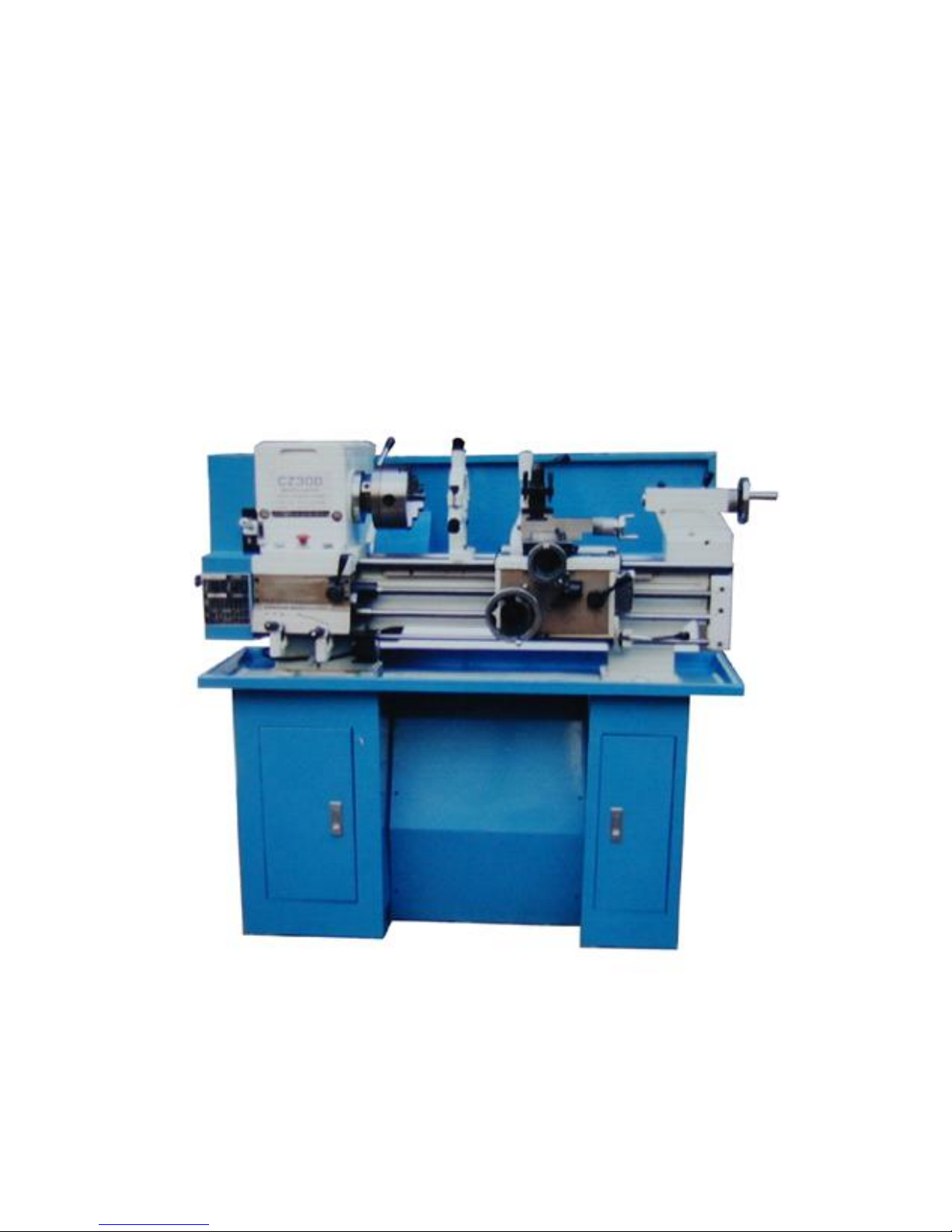
BENCH LATHE
OPERATING MANUAL
CHIZHOU JOUSEHOLD MACHINE TOOL CO., LTD.
THE PEOPLE’S REPUBLIC OF CHINA
ADDRESS: 8#, BLOCK A, CHIZHOU INDUSTRIAL ZONE, ANHUI
PROVINCE, P. R CHINA.
TEL: 0566-2612032 2612048 FAX: 0566-2612035
1
Thanks for you to have bought CZ300 CZ300/1 bench lathe, under right operating and
maintenance, the lathe will give you a long and précised service. Before operating, please study
the manual carefully. When working, please operate according to requirement and procedure
described in the manual. Besides, please keep the manual in good condition so that you may
look it up all the time.

2
CONTENTS
1 Technical data……………………………………………… 3
2 Standard accessory………………………………………… 4
3 Optional accessory………………………………………… 4
4 Electrical system…………………………………………… 4
5 General dimension…………………………………………… 6
6 Open case…………………………………………………… 7
7 Installation…………………………………………………… 7
8 Leveling……………………………………………………… 9
9 Lubrication chart…………………………………………… 11
10 Operation instruction ……………………………………… 12
11 Protection instrument……………………………………… 20
12 Check problems and repairing …………………………… 20
13 Maintenance…………………………………………… 21

3
1.SPECIFICATION
Specifications
CZ300
CZ300/1
(1) Swing over bed
305mm
305mm
(2) Swing over gap
480mm
(3) Swing over saddle
173mm
173mm
(4) Distance between centers
610mm
940mm
(5) Length of bed
1145mm
1473mm
(6) Width of bed
182mm
182mm
(7) Hole through spindle
36mm
36mm
(8) Tailstock barrel travel
92mm
92mm
(9) Cross slide travel
150mm
150mm
(10) Tool slide travel
89mm
89mm
(11) Saddle travel
520mm
850mm
(12) Taper of spindle hole
M.T.5
M.T.5
(13) Taper of center
M.T.3
M.T.3
(14) Range of spindle speed
12changes 50-1160rpm
12changes 50-1160rpm
(15) Diameter of lead screw
22mm
22mm
(16) Diameter of feed rod
19mm
19mm
(17) Thread of lead screw
8T.P.I(inch) 3mm(metric)
8T.P.I(inch) 3mm(metric)
(18) Thread can be cut
Metric 24 kinds 0.25-7.5mm
Inch 50 kinds 4-112T.P.I
(19) Motor power
1.1Kw
1.1Kw
(20) Net weight with/without stand
368Kg/308Kg
390Kg/330Kg
(21) Packing size without stand
1420×740×750mm
1780×740×750mm
(22) Packing size of stand
720×300×700mm
720×300×700mm
(23) Noise
<83dB
<83dB
4
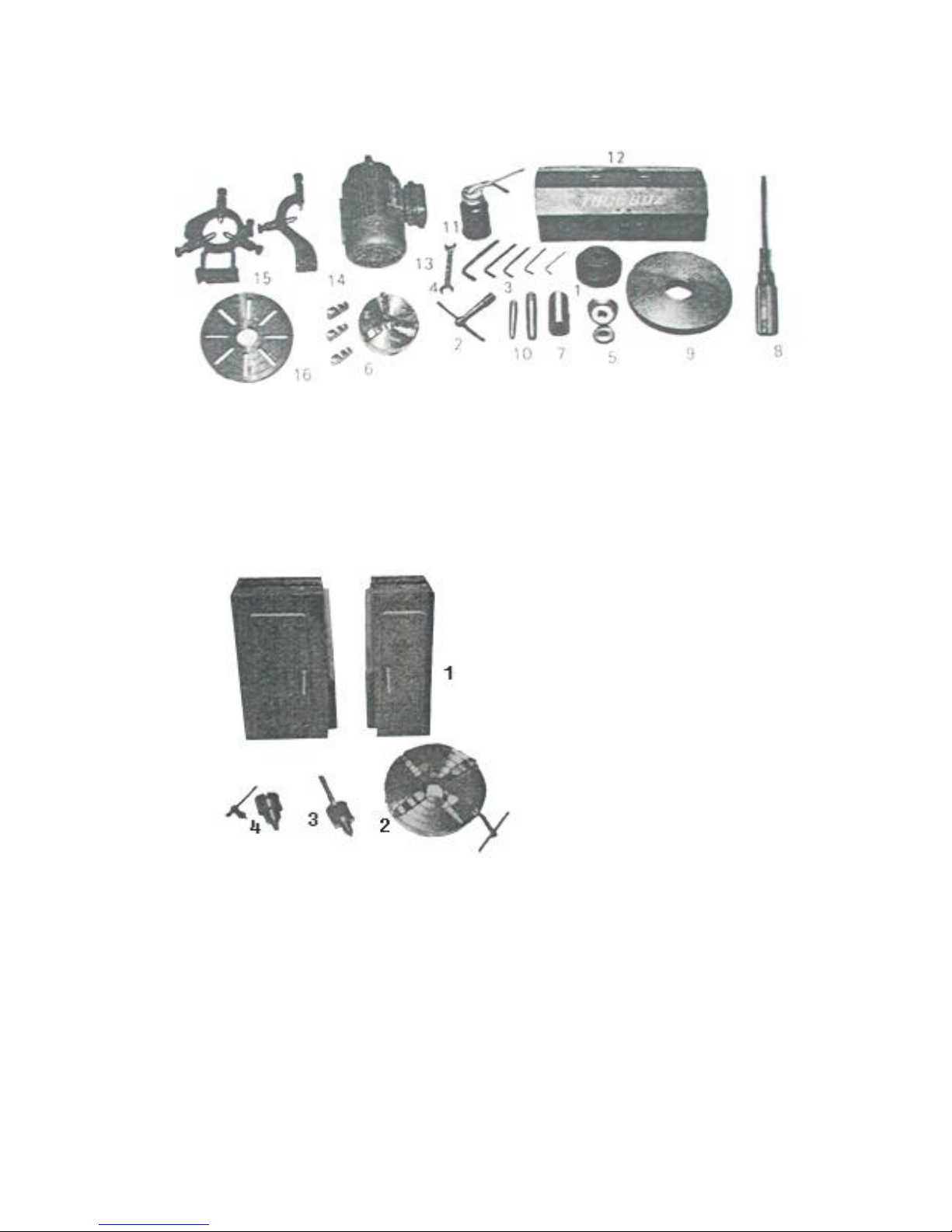
2. STANDARD ACCESSORY
1) Motor pulley 2) Tool post wrench 3) Allen wrench 4)Double end wrench
5) Change gear 6) 3-jaw chuck 7) Center sleeve 8) Screw driver
9) Back plate 10) Center 11) Oil gun 12) Tool box
13) Motor 14) Follow rest 15) Steady rest 16) Face plate
3. OPTIONALACCESSORY
4. ELECTRIC SYSTEM
Standard lathe is wired for 220V, 1 phase 50 cycles, other connection can be made as
customers’ requirements.
The electrical system in the lathe has been installed and adjusted in the factory. Generally,
please don’t open the electrical box. Before operating, wire the proper power source to lathe and
connect the ground wire. Turn on the power and check turning direction of spindle, if wrong,
first, turn off the motor and cut off the poser source, then change the wires as the wiring chart.
CAUTION:
1) IF NEED TO CHANGE THE CONNECTION IN ELECTRICAL BOX, PLEASE
1) Stand
2) 4—jaw chuck
3) Rolling center
4) Drill chuck

5
ASK FOR LOCAL REPAIRMAN OR TECHNOLOGIST TO HELP YOU TO DO AS
THE WIRING CHART, AND THE DIAMETER OF WIRE MUST B E NOT LESS THAN
1.5mm.
2) ELECTRICAL PRINCIPLE CHART ARE DESIGNED ACCORDING TO THE
CONDITOION THAT ALL KINKS OF PROTECTION INSTALLATIONS (SUCH AS
CHUCK MICROSWITCH, MAIN COVER MICROSWITCH, TOOLPOST
PROTECTION MICROSWITCH, NO VOLTAGE PROTECTION) HAVE BEEN
FITTED. PROTECTION INSTALLATIONS ARE OF SPECIAL REQUIREMENTS. IF
YOU DON’T NEED OR REQUIRE. YOUR MACHINE SHOULD BE WITHOUT THEM,
BUT ELECTRICALWIRING CHANGE SEPARATELY.
ELECTRIC PRINCIPLE CHART
THREE PHASES 220V/380V/440V
SINGLE PHASE 110V/220V

6
5. GENERAL DIMENSIONS

7
6. OPENING PACKAGE
The machine is packed in hard wooden case. When opening case, you should be careful not
to damage the surface of lathe. Look up t he operating manual and check if accessories are full, if
not, ask local seller for them.
7. INSTALLATION
CAUTION: THE MACHINE MUST FITTED FIRM AND STABLE. DON’T TURN
DOWN OR MAKE ANY MOVERMENT WITHOUT EXPECTION BECAUSE OF SHAKING,
WIND POWER, LASHING OR OTHER EXPECTED OUTER POWER OR INTERNAL
MOVEMENT FORCE ( SUCH AS INERTIA FORCE, MOTOR POWER FIRCE, ETC. )
7.1 FOUNDATION
The base for machines foundation must be solid and heavy enough to support the weight of
machine and without noticeable deflection. The floor must be fairly level.
Concrete floor is the best foundation. It provides the rigid base and minimizes vibration
form adjacent machines, the floor strength must be tested. The resting method: place a level on
the floor and put the machine on installa tion position, if the bubble show appreciable deflection,
the floor must be reinforced.
When determining the position of installation, leave a certain place in left, right, front and
back of the machine in accordance with its overall dimension and installa tion dimension of the
machine so that the operating and repairing is convenient.
If you use our stand ( optional accessory ), please first, make mark and drill eight holes in
the eight fitting hole position of base according to fitting dimension of the sta nd; secondly, cover
eight foundation bolt in the base ( note position precision when determining the fitting hole
position ). Put the stand on the base, connecting to the eight foundation bolt. Then place two
adjustable iron spacer in each down face of fro nt, back of two stand ( in order to increase the
touched space, please stagger the position of front and back adjustable iron spacer ). Fix the
connecting block of left, right of stand, fit the stand on the base. At last lift the lathe on the stand
and connect and fix the lathe to the stand by using nut and bolt.
If fit the lathe directly on the base, firstly in accordance with fitting dimension, mark and
drill hole in the base of six fitting hole position of lathe, cover six foundation bolt in the base,
place two adjustable iron spacers on the base in front and back of spindle box position and place
one adjustable iron spacer on the base in cross direction of tailstock position, then lift the lathe
on the adjustable iron spacers.
1) Fitting without stand

8
2) Fitting with stand
(1) Foundation bolt (2) Adjustable iron spacer (3) Stand (4) Chip pan (5) Lathe
7.2 LIFTING
Lifting the lathe as following figure
Put the mats in which the lifting tools connect before lifting the lathe, avoid damaging the

9
machine’s surface.
The lathe net weight is 330kg, stand weight is 60kg. When lifting, must keep the machine
in balance and avoid tilting.
The carriage, tailstock and other slide parts of the lathe are locked before leaving factory.
Don’t loosen these when lifting and should inspect to confirm whether they are locked or not in
order to prevent the parts sliding to make danger. Carefully put the machine on the base or stand
which have been fixed and fix the machine to the base or stand by bolt and nut.
7.3 CLEANING
Prior to shipment all machine and finished surfaces are coated to prevent rusting. Before
moving the carriage or tailstock, use clean solvent to remove the rust preventive coating, use
brush and solvent to clean the lead screw, rack, feed -rod, etc. Move the saddle, carriage and
tailstock to cleaned direction about 300mm, clean the ways for any residue of rust preventive
coating. Move the other way the same distance and repeat the process. Such care in the cleaning
will ensure the removal of any foreign particles and prevent the way scoring.
Lubricate the ways when clean finished.
8. LEVELING
The lathe should be kept perfectly level at all times.
LEVELING PROCEDURE:
A. Longitudinal leveling
After the bed-ways are dry after cleaning, back off the base screws, place a 6” precision
machinist spirit level over working table along longitudinal direction ( bed length direction )
move the working table at the headstock end along bed length direction, make leveling by
adjusting the adjustable iron spacer, obtain a reading. Then move the working table to the
tailstock, adjust the screw of the adjustable iron spacer until the spirit level obtain the same
reading as on the headstock end.
put the spirit level on the headstock end put the spirit level on tailstock end
B. CROSS LEVELING
Put the spirit level on the working table alo ng cross direction ( bed width direction ), move
the working table to the headstock end along bed length direction, take a reading, then move the
working table to the tailstock end, the reading at this end must be exactly the same as the other
end. No twist is permissible. If the reading is not same, adjust the screw of the adjustable iron

10
spacer to get the same reading.
Put the spirit level on headstock end put the spirit level on tailstock end
The adjustments at one end will affect the reading of the other, so the leveling procedure
should repeat many times, making necessary adjustments using staff ruler and iron spacer. After
the adjustments finished, turn sown slightly t he screw foundation bolt until they rest under slight
tension. The tension should be such that it does not change the level reading. Recheck level after
fixing the bolt, if necessary, make minor adjustment.
After the machine has been put to use for a perio d of time, check level to observe if the
original condition exists, make adjustments properly as the above mentioned way if necessary.
( make a erasable marker at one end of the spirit level to keep the same direction for every
reading. )
CAUTION: THE LOW PRECISION SPIRIT LEVEL MUST NOT BE USED.
SCHEDULE OR PERIODIC LEVEL CHECK AS A PART OF YOUR MAINTENANCE
SCHEDULE.
9. LUBRICATION CHART
11
A)—Often lubricate with fat B)—Lubricate with oil as oiler ind ication
C)—Lubricate with oil as oiler indication ●—Lubricate as every working time
CAUTION: THE LUBRICATION IS A IMPORTANCE WAY OF MACHINE
MAINTENANCE. THE QUANTITY OF LUBRICATION OIL MUST BE MODER. ATE. IF
THE LUBRICATION IS INSUFFICIENT, IT WILL AF FECT THE PRECISION OF
MACHINES AND SPEED THE MACHENE DAMAGE. IF THE LUBRECATION IS TOO
MUCH. IT WILL BE WASTEN AND MAKE THE WORKING SHOP UNCLEAR. IT IS
SUITABLE FOR THE QUANTITY OF THE LUBRICATION OIL NOT TO OVERFLOW OR
COME OFF.
10. OPERATING INSTRUCT ION

12
1. Headstock
2. Headstock cover
3. Oil guage
4. Face plate
5. Belt tension lever
6. Chuck
7. Bed
8. Rack
9. Steady rest
10. Follow rest
11. Tool post clamping lever
12. Compound slide
13. Threading dial
14. Compound slide handwheel
15. Sleeve clamping lever
16. Tailstock clamping lever
17. Tailstock handwheel
18. Tailstock
19. Saddle slide
20. Three rod support seat
21. Control lever
22. Chip pan
23. Half –nut lever
24. Cross/longitudinal feed l ever
25. Cross slide handwheel
26. Saddle handwheel
27. Control rod
28. Feed rod
29. Lead screw
30. Micro-switch box
31. Feed rod and lead screw exchange lever
32. Change gear lever
33. Change gear lever
34. Gear box
35. End face cover
36. Thread indication plate
37. Cover locking lever
38. Indication light
39. Change direction lever
40. Emergence push button
41. Start button
42. Name plate
10.1 CAUTION
A: DO NOT OPERATE THE LATHE BEFORE YOU ARE THOROUGHLY
UNDERSTAND ALL THE CONTROLS AND FUNCTION S. BEFORE CUTTING
WORKING PIECE, YOU MAY MAKE A TRIAL RUNNING IN ORDER TO FAMILIARIZE
YOUSELF WITH THE FUNCTION.

13
B: BEFORE OPERATING, CHECK OIL LEVELS AND LUBRECATION OF ALL
SLIDLING AND ROTATING PARTS. IF LUBRICATION IS NOT ENOUGH,SEE
LUBRICATION CHART AN D MAKE LUBRECATION.
C. THE LATHE HAS NO LIGHT EQUIPMENT, THE USER SHOULE PREPARE
ENOUGH FINE LIGHT EQUIPMENT AND REMOVE THE SHADOW INTERRUPTION,
AVOID LEADING DANGERS FOR THE POOR LIGHT DURING THE CUTTING
PROCESS.
D. KEEP CLAMPING THE WORKING PIECE FIRMLY PREVENT IT TO FLY OFF.
THE OUTSTANDING OF THE WORKING PIECE SHOUKD NOT BE TOO LONG IN
ORDER TO KEEP THE CUTTING PRECISION, THE RATE OF THE OUTSTANDING AND
DIAMETER SHOULD BE NOT MORE THAN 4.
E. WHEN TAKING PLACE UNEXPECTED MATTER DURING TURNING, SHOULD
PUSH THE EMERGENCY PUSH BUTTON OR TURN OFF THE POWER AT ONCE TO
STOP RUNNING.
F. WHEN NEED TO ADJUST THE LATHE OR WORKPIECE OR MACHINE TOOL,
PUSH THE PUSH BUTTON, MAKE THE MACHINE COMPLETELY STOP,THEN MAKE
THE ADJUSTMENTS.
g. CUTTING AMOUNT SELECTION: WHEN CH OOSING THE CUT AMOUNT,YOU
MUST CONSIDER THE LATHE, TOOL OR WORKPIECE RIGID, DON’T CUT
OVERLOAD, PREVENT THE DANGER FROM BREAKING. IN GENREAL, CUTTING
METAL MATERIAL AS FOLLOWING FIGURE ( SLIGHTLY ENLARGE THE CUT
AMOUNT WHEN CUTTING THE WOOD, PLASTIC, NONME TAL MATERIAL, AND SO
ON ).
WORKPIECE DIAMETER
CUT SPEED ( RPM)
CUT DEEPTH(mm)
FEED AMOUNT(mm/turn)
≥Φ150
<160
<0.5
<0.1
≥Φ100-150
<200
<0.5
<0.1
≥Φ50-100
<400
<1
<0.15
≥Φ30-50
<100
<1.5
<0.15
<Φ30
<1300
<1
<0.1
NOTE: WHEN THE RATE OF THE OUTSTANDIN G AND DIAMETER OF WORKING
PIECE IS OVER 4, THE CUT DEEPTH AND FEED AMOUNT SHOULD MAKE LESS.
H. WHEN WORKING IS OVER, TURN OFF THE POWER AND CLEAN THE LATHE.
I. WHEN DOING THE NO POWER JOB, SPECIAL AS MAINTENANCE OR REPAIR,
CUT THE MACHINE FROM THE POWER AN D KEEP SAFETY.
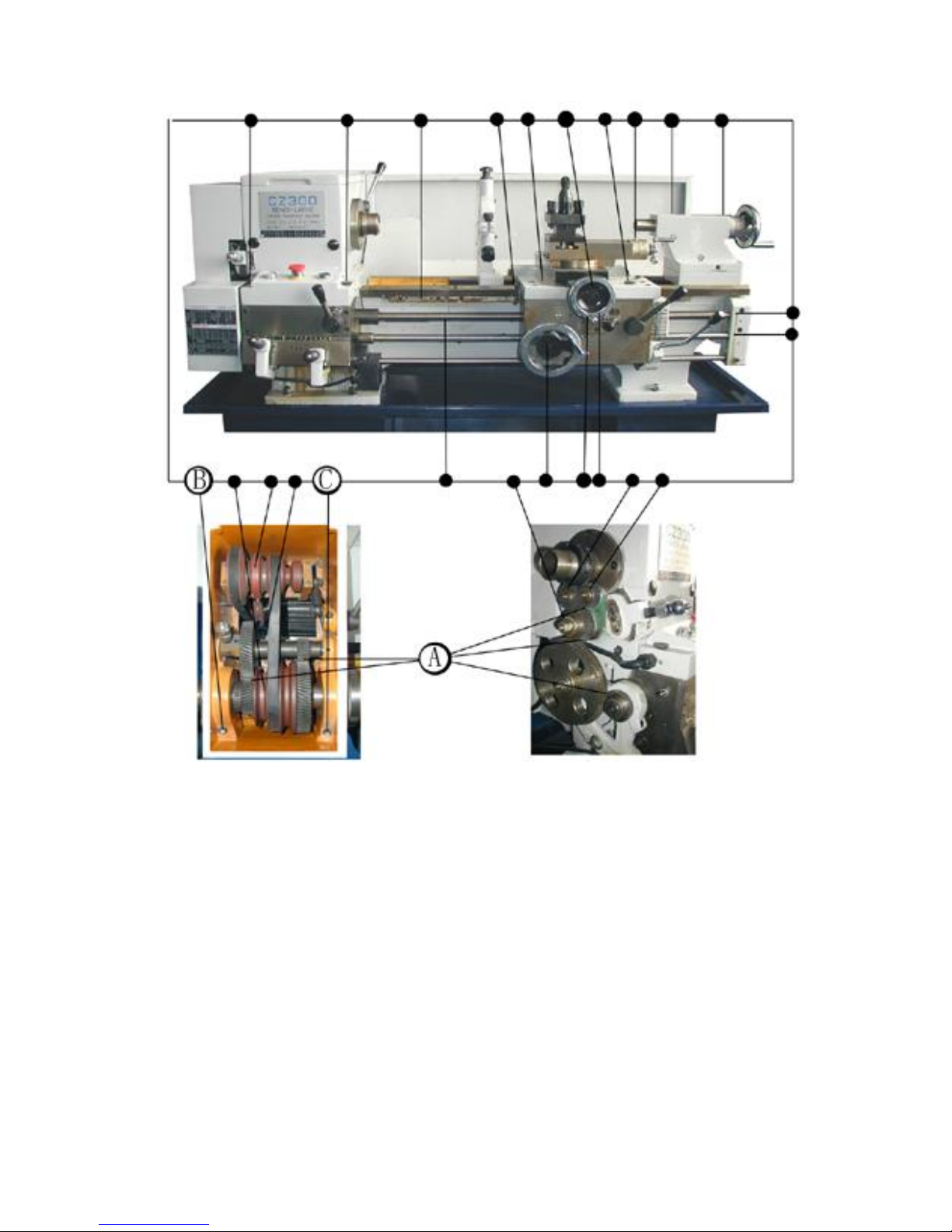
10.2 HEADSTOCK
Lift the cover can observe the headstock structure.
The headstock is equipped with 2 belts (1) (2), the tension of the belts has been adjusted. It
is advisable to check the tension before starting the machine. The belts shoul d depress about 1/2
inch by normal finger pressure. Too tight belts will damage the bearings, too loose belts will
lead belts to slide and speed the belt wear and tear. If necessary, adjust the tension of belts. See
the following figure, the link mechanism is provided for adjusting the tension of belts. If the belt

14
is loosen bolt (3) and turn out the screw rod (4) until the desired tension is set, then tighten the
hexagon bolt (3) in position.
The spindle and bearing are lubricated by the oil from two oil r eservoirs (5) which located
at each side of the headstock.
CAUTION: WHENEVER, THE SUFFICIENT OIL IN OIL RESERVOIRS MUST BE
MAINTAINED, IF NOT, PLEASE ADD OILACCORDING TO OIL GAUGE.
10.3 SPINDLE SPEED
There is gear and pulley system in the headstock.
Main spindle can obtain 12 kinds of speeds by
changing the position of belts or gears. In general
condition, light load and small diameter of
work-piece is suitable for high speed. The heavy load
and big diameter of work -piece for low speed.
CAUTION: DON’T CHANGE SPEED WHEN
THE SPINDLE IS RUNNING.
When change the spindle speed.
Please proceed as follows:
1) Move the control lever to middle position,
turn off the motor, make the spindle stop running.
2) Raise the headstock cover and pull the belt
tension lever (1) to the loose position.
3) Move the belt (2) (3) to the desired position as
the speed chart.
4) Push the belt tension lever back to the tightened position.
1——V—belt
2——V—belt
3——Bolt
4——Rod
5——Oil reservoirs
15
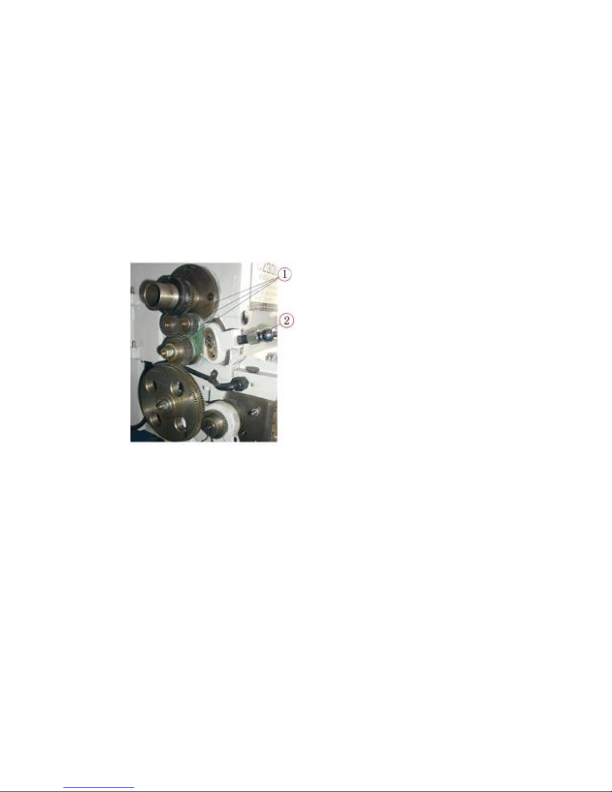
When using the back gears for low speed and heavy cutting, pleas e proceed as follows in
order to obtain the low speeds from 50 to 220 rpm.
a) Moving the control lever to middle state, turning off the motor, the spindle stop running.
b) Pull out the lock pin “A” from the gear “B” make a half turn to set it in the “out” position
as show right picture.
c) Pull the lever (4) and turn back to engage the
gears. If difficulty, slightly running the spindle by hand
and make the gears easy to engage.
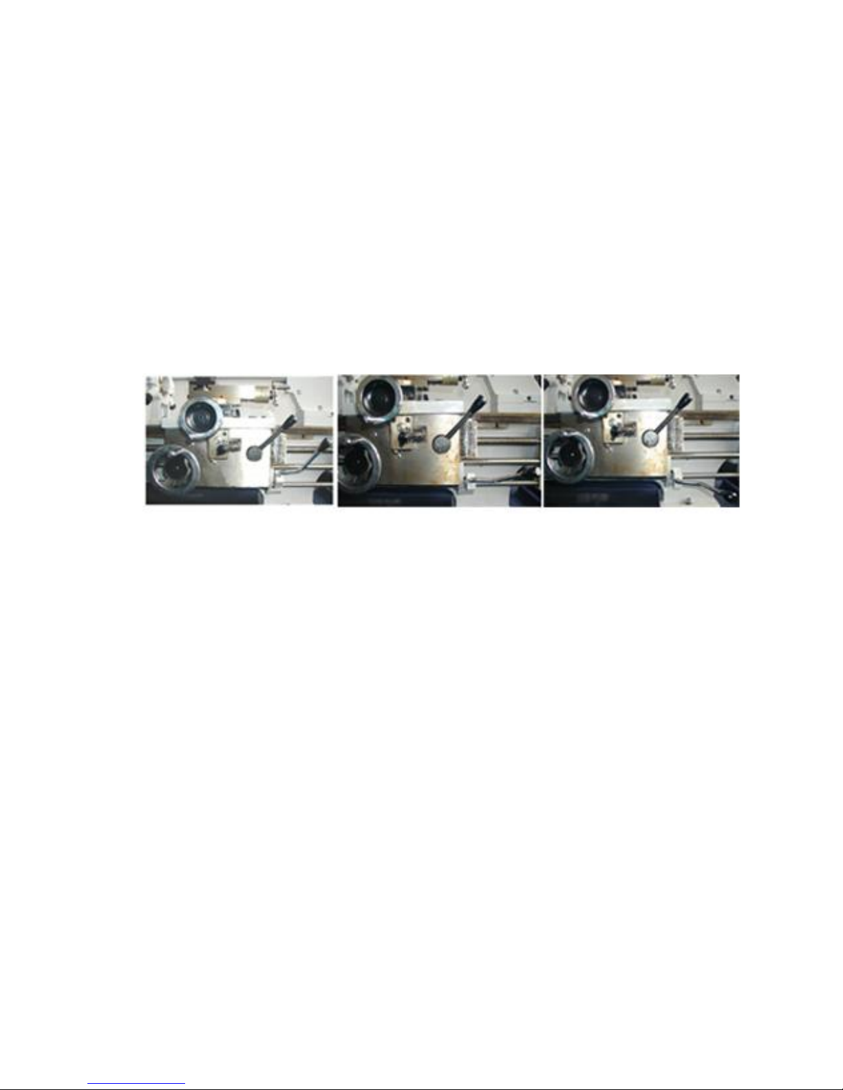
10.4 MAIN SPINDLE ROTATION
Starting, stopping, forward and reverse of spindle can be mad merely by the control lever
(1) , when using the control rod, firstly, pull the lever to headstock direction, then pull it up or
down.
Control rod on the up Control rod on the middle Control rod on the down
See the above picture, moving the control lever down the spindle will be forward rotation,
control lever up the spindle will be reverse rotation. Control lever middle the spindle will stop.
If the motor is one phase and need to change the direction of the spindle. Firstly, please move
the control lever from one side to middle, a little stop till the motor stop then move up or down,
if move control lever from one side directly to another side, the direction of the spindle don’t
change.
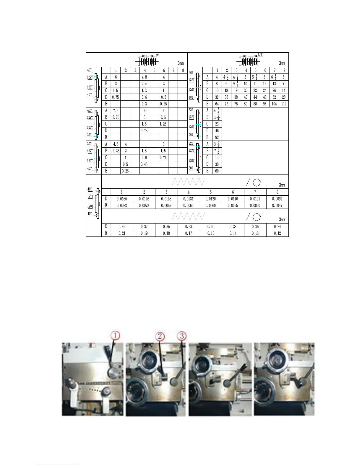
10.5 GEAR BOX
Quick—change gear system design the rate of the spindle to lead screw and feed rod when
it is used to cutting thread, external turning and facing. Quick —change gear box is controlled by
two handles. Handle (1) exists A.B.C.D.E. five positions. Handle (2) has 1. 2. 3. 4. 5. 6. 7. 8.
eight positions.
Handle (3) exists left. Middle and right three positions. Handle to right, lead screw running
and the machine is used to external turning, internal turning and facing. Handle to middle, it is
parking.
This machine can be used to cut metric and inch threads when putting the handle (1),
handle (2) to the proper position. Please change the gear A. B. C. D. when it is necessary.
1. Belt tension lever 2. V-belt 3. V-belt
4. Lever 5. Gear B 6. Pin A

16
1) Gear changing handle 2) Gear changing handle A) Gear B) Gear
3) Feed rod and lead screw changing handle C) Gear D) Gear
Half nut must keep to engaged to lead screw all time when the thread is being cut. When
the cutting is finished e very time, firstly, please make the tool back and reverse the motor, then
make the tool to the original start —cutting position and begin the next process, and working
many times at the same until the thread is finished.
CAUTION: CAN NOT CHANGE THE HANDLE (1) (2) (3) WHEN THE MACHINE
IS RUNNING.
A. THREAD AND FEED TABLE FOR IMPERIAL LEAD SCREW
THREADING THREADING
FEEDING INCHES
mmFEEDING
17
B. THREAD AND FEED TABLE FOR METRIC LEAD SCREW
THREADING
INCHES
THREADING
FEEDING
FEEDING
mm
10.6 CARRIAGE
The function of the carriage is to firml y support the tool post and carry it moving in
longitudinal and cross direction.
10.6.1 POWER FEED
When external turning and facing, please turn the lever (1) on the gear box to left and make
the feed rod rotation.
Need to power feed in longitudinal direct ion, up–engage the cross/longitudinal feed lever (2) .
Need to power feed in cross direction, down –engage the cross/longitudinal feed lever (2).
(1) Feed rod/lead screw changing (2) Cross/longitudinal Feed changing (3) Half nut lever
While the cross /longitudinal feed lever is in the feed position, the half nut lever (3) can not
18
be engaged, the built –in safety interlock mechanism will prevent simultaneous engagement of
(2) and (3).
For threading, put the lever (1) on the gear box to the right and the lead screw rotating,
then make the cross/longitudinal feed lever (2) on the middle and engage the half nut (3), the
result is the lead screw rotating and to make the carriage moving to the right and left.
CAUTION: DO NOT FORCE THE HALF NUT LEVER WHILE ENGAGING WITH
THE LEAD SCREW
When power feed, the direction of spindle rotating, carriage moving and cross –slide
moving nave been designed by mechanism, for example, when the spindle clockwise rotating,
the carriage move to left, conversely to right.
3-star gear system can change the carriage travel direction too, when the spindle clockwise
rotating and the lever (2) on up position, it make the carriage move left, the lever (2) on down
position, carriage move right. The lever (2) on middle, the carriage stop moving.
10.6.2 THREADING DIAL
When the pitch proportion of lead screw and work -piece thread is not integer times and
need to open the half –nut while cutting, it is necessary to use the t hread dial to control tools
and prevent the mixed screw.
The threading dial is located on the right or left side of the apron.
It performs the important function of indicating the proper time to engage the half nut lever
so that the tool will enter the sam e groove of the thread on each successive cut. The dial is
marked with lines numbered 1. 2. 3. 4. and in between are lines with no number. These are half
lines and are called unnumbered lines. The dial when engaged with the lead screw will cause the
rotation of the dial, A single line is marked on the housing of the threading dial ( fixed line ).
The instruction plate riveted on the threading dial shows the selection and sequence of
matching the revolving lines with the fixed line.
For thread cutting, engag e the half –nuts at the appropriate numbers shown on the scale
column of the threading dial plate, 1 - 4 on the scale means the half –nuts can be engaged on any
of the numbered lines 1 - 2 –3–4 . For each successive cuts only numbered lines must be used.
1-3/2 –4 on the scale means the half –nut can be engaged on 1 and 3 or 2 and 4 for successive
cuts, For example, when you engage the half – nut on the numbered line “1” for the first cut,
after that for successive cuts, the half –nut just be engaged on the numbered line “1” or “3” , If
you engage the half – nut on the numbered line “2” for the first cut. After that for successive
(1) 3-star gear
(2) Changing direction lever

19
(1) Compound slide (up)
(2) Cross slide (up
(3) Screw
(4) Tool post clamping lever)
(5) Compound slide (down)
(6) Handle wheel
cuts, the half – nut just be engaged on the numbered line “2”
or “4”. 1- 8 means the half –nuts can be engaged on any line,
numbered or unnumbered.
If half –nut engage with the lead screw all time while
cutting the thread, no need to use threading dial, In this case,
after finished each successive cut, firstly, back the tool and
reverse the motor, then move the tool to the la st start –
cutting position and make the next successive cut.
10.7 FOUR POSITIONS TOOL POST
Main function of tool post is to fix tool, If necessary, tool
post may fix more than one tool ( at most 4 ), Tool thickness
must be less than tool groove, When i nstalling tool again , should confirm tool head direction to
work-piece revolving center line, permitting to use iron spacer to adjust, after adjusting correctly,
please fix the tool. If need to turn the tool post, turn the tool post locking handle counter
clockwise to loosen the locking handle and turn the tool post to the position you needed and
then turn the tool post lock handle clockwise to make tool post lock.
10.8 COMPOUND SLIDE
Using the compound slide can cut taper , When cutting taper, please loosen the screw on the
saddle, round the compound slide, let the graduated line towards the graduation number on the
saddle. Then fix the screw, round the driving hand wheel, the tool post move the tool, now there
is a angle between the traveling line and turning line of spindle, thus you can turn taper.
10.9 TAILSTOCK
The tailstock slides along the bed -ways freely and can be locked in any position by the
clamp lever. There is an end pin to stop the tailstock sliding down. Rot ating the tailstock hand
wheel can slide the quill. The quill can be locked by the quill lock lever. Before leaving the
factory, it will be sure that it is the same line between the tailstock center and spindle center. For
(1) Threading dial
This manual suits for next models
1
Table of contents


