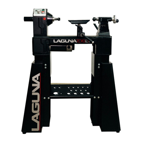
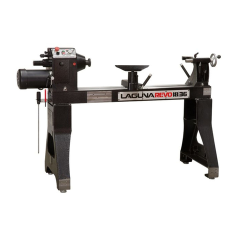
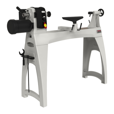
Laguna Tools REVO 24-36 User manual

1
Original Instructions

EC DECLARATION OF CONFORMITY
We
(Manufacturer)
Laguna Tools Inc.
2072 Alton Parkway, Irvine, California 92606, USA
Declare that the product name: Wood Lathe
Model Name :
REVO12│16, REVO 15│24, REVO 18│36, REVO 24│36
Conform with the essential safety requirements of the relevant European Directive:
-Machinery Directive 2006/42/EC
-Electromagnetic Compatibility Directive 2014/30/EU
The person who compile technical file established within the EU:
Name:
IGM nastroje a stroje s.r.o.
Address:
Tel.:
Email:
Ke Kopanine 560, Tuchomerice , CZ-252 67
+420 220 950 910
sales@igmtools.com
Mounting and connecting instructions defined in catalogues and technical construction files must be respected
by the user.
They are based on the following standards:
EN ISO 12100:2010 Safety of Machinery - General principles for design / Risk Assessment and Risk reduction.
EN 60204-1:2006+AC:2010 Safety of machinery – Electrical equipment of machines, part 1 : General
requirements.
EN 13849-1:2015Safety of machinery – Safety – related parts of control systems Part 1: General principles for
design
EN 50370 -1:2005Electromagnetic compatibility (EMC) – Product family standard for machine tools – Part 1:
Emission.
EN 50370 -2:2003 Electromagnetic compatibility (EMC) – Product family standard for machine tools – Part 2:
Immunity.
EN 61000-4-2: 2009 Electrostatic (ESD)
EN 61000-4-4: 2012 Electrical fast transient/burst requirements (EFT/Burst)
EN 61000-4-6: 2014Immunity to conducted disturbances, induced by radio-frequency fields (CS)
Responsible for the documentation: Head Product Management, Laguna Tools Inc.
Name : Torben Helshoj
Responsibility
Authorized Signature
Date : Oct. 15, 2021
Place : Laguna Tools Inc.
2072 Alton Parkway, Irvine, California 92606, USA
Telephone: +1 800 234-1976
Fax: +1 949 474-0150

DECLARATION OF CONFORM ITY
We
(Manufacturer)
Laguna Tools Inc.
2072 Alton Parkway, Irvine, California 92606, USA
Declare that the product name: Wood Lathe
Model Name : REVO 12|16, REVO 15|24, REVO 18|36, REVO 24|36
Fulfils all the relevant provisions of:
- The Supply of Machinery (Safety) Regulations 2008 (as amended)
- The Electromagnetic Compatibility Regulations 2016 (as amended)
Person authorized to compile the technical file:
Name: Charnwood Machinery Ltd
Address: Cedar Court, Walker Road, Hilltop Industrial Estate, Bardon, Leicestershire, LE67 1TU, United Kingdom
The name, address and identification number of the approved body which carried out the type-examination
Name: SGS United Kingdom Limited
Address: Unit 12A & 12B, Bowburn South Industrial Estate, Durham, DH6 5AD, United Kingdom
Type Examination no.: MCA 2652
Approved Body no.: 0120
Mounting and connecting instructions defined in catalogues and technical construction files must be respected by
the user.
They are based on the following standards
EN ISO 12100:2010 Safety of Machinery - General principles for design / Risk Assessment and Risk reduction.
EN 60204-1:2018/ Safety of machinery – Electrical equipment of machines, part 1: General requirements.
EN 13849-1:2015 Safety of machinery – Safety – related parts of control systems Part 1: General principles for
design
EN 50370 -1:2005 Electromagnetic compatibility (EMC) – Product family standard for machine tools – Part 1:
Emission.
EN 50370 -2:2003 Electromagnetic compatibility (EMC) – Product family standard for machine tools – Part 2:
Immunity.
EN 61000-4-2: 2009 Electrostatic (ESD)
EN 61000-4-4: 2012 Electrical fast transient/burst requirements (EFT/Burst)
EN 61000-4-6: 2014 Immunity to conducted disturbances, induced by radio-frequency fields (CS)
The relevant technical documentation has been compiled in accordance with Annex VII, Part B of The Supply of
Machinery (Safety) Regulations 2008(as amended). We undertake, in response to a reasoned request, to supply it
to the market surveillance authorities within a reasonable period.
Name : Torben Helshoj
Responsibility
Authorized Signature
Date : Oct. 15, 2021
Place : Laguna Tools Inc.
2072 Alton Parkway, Irvine, California 92606, USA
Telephone: +1 800 234-1976
Fax: +1 949 474-0150

3
Table of contents.
Page number
Safety Rules
4
Warranty
8
Noise emission
9
Specification sheet
10
Receiving your machine
11
Introduction to your machine
12
Parts of the machine
12
What you will receive with the machine
17
Where to locate your machine
20
Unpacking your machine
20
Assembly and setup
22
Maintenance
34
Troubleshooting
37
Electrical drawing
39
Exploded view drawings
42

SAFETY RULES
1. KEEP GUARDSIN PLACE and in working order.
2. REMOVE ADJUSTING KEYS AND WRENCHES.
Form habit of checking to see that keys and ad-
justing wrenches are removed from tool before
turning it on.
3. KEEP WORK AREA CLEAN. Cluttered areas and
benches invite accidents.
4. DON'T USE IN DANGEROUS ENVIRONMENT.
Don't use power tools in damp or wet locations,
or expose them to rain. Keep work area well
lighted.
5. KEEP CHILDREN AWAY. All visitors should be
kept safe distance from work area.
6. MAKE WORKSHOP CHILD PROOF with padlocks,
masterswitches, or by removingstarter keys.
7. DON'T FORCE TOOL. It will do the job better and
safer at the rate for which it was designed.
8. USE RIGHT TOOL. Don't force tool or attachment
to do a job for which it was not designed.
9. USE PROPER EXTENSION CORD. Make sure
your extension cord is in good condition. When
using an extension cord, be sure to use one
heavy enough to carry the current your product
will draw. An undersized cord will cause a drop
in line voltage resulting in loss of power and
overheating. Table A (on the next page) shows
the correct size to use depending on cord length
and nameplate ampere rating. If in doubt, use
the next heavier gage. The smaller the gage nu-
mber, the heavierthe cord.
10. WEAR PROPER APPAREL. Do not wear loose
clothing, gloves, neckties, rings, bracelets, or
other jewelry which may get caught in moving
parts. Nonslip footwear is recommended. Wear
protective hair covering to contain long hair.
11. ALWAYS USE SAFETY GLASSES. Also use face
or dust mask if cutting operation is dusty. Eve-
ryday eyeglasses only have impact resistant
lenses, they are NOT safety glasses.
12. SECURE WORK. Use clamps or a vise to hold
work when practical. It's safer than using your
hand and it frees both hands to operate tool.
13. DON'T OVERREACH. Keep proper footing and
balance at all times.
14. MAINTAIN TOOLS WITH CARE. Keep tools sharp
and clean for best and safest performance. Fol-
low instructions for lubricating and changing ac-
cessories.
15. DISCONNECT TOOLS before servicing; when
changing accessories, such as blades, bits, cut-
ters, and the like.
16. REDUCE THE RISK OF UNINTENTIONAL STA-
TING. Make sure switch is in off position before
plugging in.
17. USE RECOMMENDED ACCESSORIES. Consult
the owner's manual for recommended acces-
sories. The use of improper accessories may
cause risk of injury to persons.
18. NEVER STAND ON TOOL. Serious injury could
occur if the tool is tipped or if the cutting tool is
unintentionally contacted.
19. CHECK DAMAGED PARTS. Before further use of
the tool, a guard or other part that is damaged
should be carefully checked to determine that
it will operate properly and perform its intended
function - check for alignment of moving parts,
binding of moving parts, breakage of parts,
mounting, and any other conditions that may
affect its operation. A guard or other part that
is damaged should be properly repaired or re-
placed.
20. DIRECTION OF FEED. Feed work into a blade or
cutter against the direction of rotation of the
blade or cutter only.
21. NEVER LEAVE TOOL RUNNING UNATTENDED.
TURN POWER OFF. Don't leave tool until it co-
mes to a complete stop.
Some dust created by power sanding, sawing, grinding, drilling and other construction activities contain chemicals
known to cause cancer, birth defects or other reproductive harm. Some examples of these chemicals are:
•Leadfrom lead based paint.
•Crystallinesilicafrom bricks, cement,and other masonry products.
•Arsenicand chromium from chemically treated lumber.
Your risk of exposure varies, depending on how often you do this type of work. To reduce your exposure to these
chemicals, work in a well-ventilated area and work with approved safety equipment, such as face or dust masks
4
5
Location of warning signs

6
Wood lathe
Wood turning lathes are typically used to shape wood into cylindrical profiles. Objects made
on a wood lathe include such items as furniture legs, lamp posts, baseball bats, bowls and
other ornamental forms. Wood lathe tooling consists of fixturing and securing devices for the
work piece, a moveable tool rest, and hand-held cutting tools in the form of long handled
gouges, skews, scrapers, and parting tools. Specialty tooling is also available for internal
shaping and surface development.

7
Locking the lathe
It is strongly recommended that the lathe is never left unattended in the unlocked condition.
To lock the machine it is recommended that a cover (not supplied) is made to lock the control
panel. We have supplied two concepts for locking the panel (see below). The cover can be
made from wood or plastic, two covers (not supplied) are made to lock the control panels on
both headstock and remote controller. We have supplied four concepts for locking the control
panel (see below).
First, push down the emergency stop. Then lock the cover together by putting padlocks [not
included] on the two handles on the control panel. To safeguard your machine from
unauthorized operation and accidental starting by young children, the use of padlocks is
strongly recommended.
Wooden safety cover
Padlocks
Wooden safety cover
Padlocks
Plastic safety cover
Padlocks
Plastic safety cover
Padlocks

8
Limited Warranty.
New woodworking machines sold by Laguna Tools carry a one-year warranty from the date of
shipping. Laguna Tools guarantees all new machines sold to be free of manufacturer's
defective workmanship, parts, and materials.
We will repair or replace, without charge, any parts determined by Laguna Tools, Inc. to be a
manufacturer's defect. We require the defective item/part to be returned to Laguna Tools. In
the event the item/part is determined to be
damaged due to lack of maintenance, cleaning or misuse/abuse, the customer
will be responsible for the cost to replace the item/part, plus all related shipping charges.
This limited warranty does not apply to natural disasters, acts of
terrorism, normal wear and tear, product failure due to lack of maintenance or cleaning,
damage caused by accident, neglect, lack of or inadequate dust
collection, misuse/abuse or damage caused when repair or alterations have
been made or attempted by others.
Laguna Tools, Inc. is not responsible for additional tools or modifications sold or performed
(other than from/by Laguna Tools, Inc.) on any Laguna Tools, Inc. woodworking machine.
Warranty may be voided upon the addition of such noted tools and/or modifications,
determined on a case-by-case basis.
Normal user alignment, adjustment, tuning and machine settings are not
covered by this warranty. It is the responsibility of the user to understand
basic woodworking machinery settings and procedures and to properly maintain the
equipment in accordance with the standards provided by the manufacturer.
Parts, under warranty, are shipped at Laguna Tools, Inc's cost either by
common carrier, FedEx Ground service or a similar method.
Technical support to install replacement parts is primarily provided by phone, fax, or e-mail.
The labor required to install replacement parts is the responsibility of the user.
Laguna Tools is not responsible for damage or loss caused by a freight company or other
circumstances not in our control.
Only new machines sold to the original owner are covered by this warranty.
For warranty repair information, call 1-800-332-4094.

9
Noise Emission.
Equivalent A-weighted Sound pressure level according to EN ISO 3746: 75.66 dB(A)
Uncertainty, K in decibels: 4.0 dB (A) according to EN ISO 4871
The figure quoted is emission levels and are not necessarily safe working levels.
Whilst there is a correlation between the emission and exposure levels, this cannot
be used reliably to determine whether or not further precautions are required.
Factors that influence the actual level of exposure of the workforce include
characteristics of the work room, the other sources of noise, etc. i.e. the number of
machines and other adjacent processes. Also the permissible exposure level can
vary from country to country, This information, however, will enable the user of the
machine to make a better evaluation of the hazard and risk.

10
Specification sheet.
Motor
Induction,1420RPM, 3 HP 230V 3Ph
Voltage
230v 50hz 1Ph input
Recommended
breaker size
15 amp
Swing over bed
24" (609mm)
Swing over banjo
19.75" (501mm)
Outboard swing
max
38" (965mm)
Distance between
centers
36" (914mm)
Floor to spindle
center
44.5"(1130mm)
Floor to bed height
32.5" with pads (826mm)
Floor space
W60" D26" H52.25"(1524mm, 660mm, 1327mm)
Tool rest
12" (305mm)
Speed range high
135 - 3500 RPM
Speed range low
50 - 1300 RPM
VFD
Delta variable frequency drive
Drive belt
Poly-groove drive belt with easy access
Spindle
M33 x 3.5 right hand thread (M30 x 3.5 for Australia)
Spindle taper
MT 2
Spindle lock
Spring loaded
Spindle index
14 / 36 / 48 positions with lock
Headstock &
tailstock bore
0.375" dia (9.5mm dia)
Tail stock travel
4.5" (114mm)
Tail stock removal
Self- ejecting
Tailstock tapers
MT 2
Face plate
3" diameter (76mm)
Bed material
Steel
Weight (Net / ship)
532/560 lbs (242kg / 255 kg)

11
Receiving your machine.
Note. It is probable that your machine will be delivered by a third party. Before you unpack
your new machine you will need to first inspect the packing, invoice and shipping documents
supplied by the driver.
Insure that there is no visible damage to the packing or the machine. You need to do this prior
to the driver leaving. All damage must be noted on the delivery documents and signed by you
and the delivery driver. You must then contact the seller (Laguna Tools) as soon as practical.
If damage is found after delivery, contact the seller as soon as is practical.
Note. It is probable that you will find sawdust within your machine. This is because the
machine has been tested prior to shipment from the factory and or Laguna Tools.
Laguna Tools endeavours to test machines prior to shipping to customers. As movement can
take place during transportation it must be noted that additional machine movement can take
place between Laguna Tools and the end user and some adjustments may have to be
undertaken by the customer. These adjustments are covered in the various sections of this
manual.

12
Introduction to lathes.
This machine is designed to give you years of safe service. Read this owner's manual in its
entirety before assembly or use.
Parts of the lathe.
The lathe consists of a number of major parts, which are discussed in this manual. Take the
time to read this section and become familiar with the machine.
Head stock Tool rest Tail stock Drive &live center storage
Tool storage Leg Bed Banjo Adjustable feet Leg

13
Identification.
There is a plate at the back of the machine listing all the
manufacturing data, including the serial number, model,
etc.
Lathe Bed.
The bed is a machined heavy steel welded construction.
Underside of lathe bed
Model REVO 24
|
36
Power
1~230V 50Hz 9A P2=2.2kw S1
Specification n0=0 3500 /min SCCR=6k A
M33x3.5 / MT-2 / 10.5mm
Article No. LAGUNA-L-0016 Weight 242kg
Series No. Year
LAGUNA TOOLS 2072 Alton Parkway. Irvine, CA 92606
www.lagunatools.com
M30 x 3.5 Spindle Thread for Australia.

14
Lathe legs.
The Legs are cast iron, and their heavy construction gives the machine a low center of gravity
and ensures that it is very stable. The legs are supplied with adjustable feet to allow the
machine to be leveled.
Legs with adjustable feet assembled
Head stock.
The head stock is cast iron and houses the variable speed control and motor. The
Spindle can be locked in 14 / 36 and 48 positions.

15
Headstock removed from the
bed
Head or remote selection
switch
Tail stock.
The tail stock is of cast iron construction, and the spindle has a travel of 4 1/2 in. It can
accommodate centers and other tools which have a number 2 Morse Taper. The tail stock can
be moved to any position on the lathe bed and locked to suit the job at hand.
Tool rest.
The tool rest can be moved to any position on the lathe bed and locked to suit the job at hand.
The tool rest has a tall profile to allow the bowl turner to turn steep angles. The leading edge
is made from 6mm hardened steel.
Tailstock viewed from the back
Tailstock viewed from the front

16
Electrical system.
220V: The electrical control system (VFD) is housed at the back of the head stock, The VFD
converts single phase 220v to three phase. There is a speed readout at the front of the lathe
with controls to fine adjust the RPM of the spindle. . A power cord with 220V plug is provided.
There are two electrical sockets to the side of the VFD..
Tool rest assembled to the bed
Tool rest
VFD with cover open
Power sockets

17
Tool storage.
A tool storage bracket which can be mounted on either leg.
What you will receive with the lathe.
Tool storage bracket

18
Head stock Tool rest Tail stock Drive &live center storage
Tool storage Leg Bed Banjo Adjustable feet Leg
Remote controller
Face plate Tool rack Rotating center Adjustable feet Tail stock bracket

19
Removal tool Drive center Knock out rod Head stock bracket
Tail stock knob Tool rest comes fitted to banjo
Remote brackets and hardware
Table of contents
Other Laguna Tools Lathe manuals

Laguna Tools
Laguna Tools MTP105 User manual

Laguna Tools
Laguna Tools CL1200 User manual

Laguna Tools
Laguna Tools MLA0230-175 User manual

Laguna Tools
Laguna Tools Revo 10x16 Mini User manual

Laguna Tools
Laguna Tools REVO 10 User manual

Laguna Tools
Laguna Tools REVO 1216 User manual

Laguna Tools
Laguna Tools REVO 1216 User manual

Laguna Tools
Laguna Tools Platinum 18/47 Series User manual

Laguna Tools
Laguna Tools REVO 18 User manual