Other manuals for Mark-V FT-1000MP
9
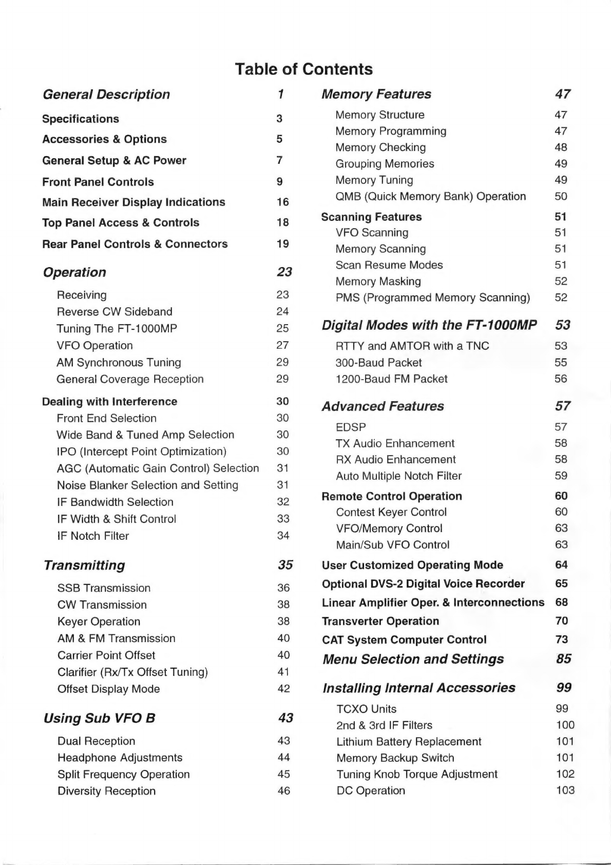
Table of contents
Other Yaesu Transceiver manuals
Yaesu
Yaesu FT-2000 - MENU MODE LIST User manual
Yaesu VX-8DR User manual
Yaesu FT-897 Manual
Yaesu FTDX 1200 Series Product guide
Yaesu FT-857D User manual
Yaesu VX-2500V User manual
Yaesu FT-2800M Manual
Yaesu FTM-350R - SOFTWARE UPDATE PROCEDURE 7110 Manual
Yaesu FT-950 Technical manual
Yaesu FT-817 - Manual
Yaesu FT-847 Manual
Yaesu FT-901DM User manual
Yaesu FT-727R User manual
Yaesu FTM-100DR User manual
Yaesu FT-8900R User manual
Yaesu FTDX101MP User manual
Yaesu FT-270R User manual
Yaesu FT-857 series Manual
Yaesu FT-100 Micro Mobile User manual
Yaesu FT-707 User manual
Yaesu FT-847 User manual
Yaesu FT-991 Manual
Kenwood
Kenwood ProTalk TK-3201 instruction manual
Mizuho
Mizuho MX-2 Operating & assembly instruction
Kenwood TK-3180 Manuale di istruzioni
Blitz
Blitz MJ-398U instruction manual
Utilicom
Utilicom LongRanger 2050 Operator's manual
Standart
Standart HX290UKA Service manual
Altronix
Altronix Pace1PTM installation guide
Kirisun
Kirisun PT2208 instruction manual
ELECRAFT
ELECRAFT KX2 manual
Zodiac
Zodiac K3 user manual
Assa Abloy
Assa Abloy SecureComm HKC GSM-WIFI U manual
Kenwood TK-2217 Service manual
Siemens
Siemens PSO 4000 Quick reference guide
Kenwood TS-590SG instruction manual
Midland
Midland G8E-BT Instruction guide
ComNav
ComNav Mariner X2 installation manual
Uniden
Uniden UH820 Series owner's manual
Standard Horizon
Standard Horizon HX320E owner's manual