Chore-Time 108 FLEX-AUGER User manual
FLEX-AUGER®Feed Delivery System
Installation Instruction
for
Model 108 F LEX-AUGER®Feed Delivery Systems
For additional parts and information, contact your nearest Chore-Time distributor or representative.
Find your nearest distributor at: www.choretime.com/contacts
CTB, Inc.
PO Box 2000
Milford, Indiana 46542-2000 USA
Phone (574) 658-4101 Fax (877) 730-8825
Email: choretime@choretime.com
Internet: www.choretime.com
MA1032FMay 2020
Installation and Operators Manual
Installation and Operators Manual

Contents
Topic Page
MA1032F 2
Limited Warranty. . . . . . . . . . . . . . . . . . . . . . . . . . . . . . . . . . . . . . . . . . . . . . . . . . . . . . . . . . . . . . . . 4
Safety and General Information . . . . . . . . . . . . . . . . . . . . . . . . . . . . . . . . . . . . . . . . . . . . . . . . . . . . 5
Follow Safety Instructions . . . . . . . . . . . . . . . . . . . . . . . . . . . . . . . . . . . . . . . . . . . . . . . . . . . . . . . . . . . . . . 5
Decal Descriptions . . . . . . . . . . . . . . . . . . . . . . . . . . . . . . . . . . . . . . . . . . . . . . . . . . . . . . . . . . . . . . . . . . . . 5
DANGER: Moving Auger. . . . . . . . . . . . . . . . . . . . . . . . . . . . . . . . . . . . . . . . . . . . . . . . . . . . . . . . . . . 5
DANGER: Electrical Hazard . . . . . . . . . . . . . . . . . . . . . . . . . . . . . . . . . . . . . . . . . . . . . . . . . . . . . . . . 5
DANGER: Springing Auger . . . . . . . . . . . . . . . . . . . . . . . . . . . . . . . . . . . . . . . . . . . . . . . . . . . . . . . . . 5
General Information. . . . . . . . . . . . . . . . . . . . . . . . . . . . . . . . . . . . . . . . . . . . . . . . . . . . . . . . . . . . . . 6
Tools Needed to install your model 108 System include: . . . . . . . . . . . . . . . . . . . . . . . . . . . . . . . . . . . . . . 6
Capacities and Specifications of the Model 108 Feed Delivery System . . . . . . . . . . . . . . . . . . . . . . . . . . . 7
Glossary of Terms. . . . . . . . . . . . . . . . . . . . . . . . . . . . . . . . . . . . . . . . . . . . . . . . . . . . . . . . . . . . . . . . . . . . . 8
Planning the Model 108 Feed Delivery System . . . . . . . . . . . . . . . . . . . . . . . . . . . . . . . . . . . . . . . . . . . . . . 9
Planning. . . . . . . . . . . . . . . . . . . . . . . . . . . . . . . . . . . . . . . . . . . . . . . . . . . . . . . . . . . . . . . . . . . . . . . 11
Systems Not Allowed . . . . . . . . . . . . . . . . . . . . . . . . . . . . . . . . . . . . . . . . . . . . . . . . . . . . . . . . . . . . . . . . . .13
Model 108 Bin Placement Chart. . . . . . . . . . . . . . . . . . . . . . . . . . . . . . . . . . . . . . . . . . . . . . . . . . . . . . . . . .14
Model 108 Bin Placement Chart (with In-Line or Rotated Screeners). . . . . . . . . . . . . . . . . . . . . . . . . . . . .15
30° or Straight-Out Bin Boot with Feed Screener Boot Rotated 90° . . . . . . . . . . . . . . . . . . . . . . . . . . . . . .16
30° Bin Boot with Feed Screener . . . . . . . . . . . . . . . . . . . . . . . . . . . . . . . . . . . . . . . . . . . . . . . . . . . . . . . . .16
Straight-Out Bin Boot with Feed Screener . . . . . . . . . . . . . . . . . . . . . . . . . . . . . . . . . . . . . . . . . . . . . . . . . .17
Installation. . . . . . . . . . . . . . . . . . . . . . . . . . . . . . . . . . . . . . . . . . . . . . . . . . . . . . . . . . . . . . . . . . . . . 18
Bin Location . . . . . . . . . . . . . . . . . . . . . . . . . . . . . . . . . . . . . . . . . . . . . . . . . . . . . . . . . . . . . . . . . . . . . . . . .18
Boot Installation . . . . . . . . . . . . . . . . . . . . . . . . . . . . . . . . . . . . . . . . . . . . . . . . . . . . . . . . . . . . . . . . . . . . . .18
Auger Tube Installation . . . . . . . . . . . . . . . . . . . . . . . . . . . . . . . . . . . . . . . . . . . . . . . . . . . . . . . . . . . . . . . .19
Outlet Drop Installation . . . . . . . . . . . . . . . . . . . . . . . . . . . . . . . . . . . . . . . . . . . . . . . . . . . . . . . . . . . . . . . .20
Supporting the System Inside the Building . . . . . . . . . . . . . . . . . . . . . . . . . . . . . . . . . . . . . . . . . . . . . . . . .22
Supporting the System Outside the Building . . . . . . . . . . . . . . . . . . . . . . . . . . . . . . . . . . . . . . . . . . . . . . . .23
Screeners . . . . . . . . . . . . . . . . . . . . . . . . . . . . . . . . . . . . . . . . . . . . . . . . . . . . . . . . . . . . . . . . . . . . . . . .23
High Rise Auger Tube Support . . . . . . . . . . . . . . . . . . . . . . . . . . . . . . . . . . . . . . . . . . . . . . . . . . . . . . .23
Long Elevated Systems . . . . . . . . . . . . . . . . . . . . . . . . . . . . . . . . . . . . . . . . . . . . . . . . . . . . . . . . . . . . .24
Bin to Bin Support Systems. . . . . . . . . . . . . . . . . . . . . . . . . . . . . . . . . . . . . . . . . . . . . . . . . . . . . . . . . .24
Straight-Through Tandem Systems . . . . . . . . . . . . . . . . . . . . . . . . . . . . . . . . . . . . . . . . . . . . . . . . . . . .24
Control Unit & Power Unit Installation . . . . . . . . . . . . . . . . . . . . . . . . . . . . . . . . . . . . . . . . . . . . . . . .25
Belt Drive Control Unit Installation . . . . . . . . . . . . . . . . . . . . . . . . . . . . . . . . . . . . . . . . . . . . . . . . . . . . . . .26
Auger Installation . . . . . . . . . . . . . . . . . . . . . . . . . . . . . . . . . . . . . . . . . . . . . . . . . . . . . . . . . . . . . . . . . . . . .26
Cover Plate Installation. . . . . . . . . . . . . . . . . . . . . . . . . . . . . . . . . . . . . . . . . . . . . . . . . . . . . . . . . . . . . . . . .28
Auger Brazing. . . . . . . . . . . . . . . . . . . . . . . . . . . . . . . . . . . . . . . . . . . . . . . . . . . . . . . . . . . . . . . . . . . . . . . .28
Restrictor Adjustment . . . . . . . . . . . . . . . . . . . . . . . . . . . . . . . . . . . . . . . . . . . . . . . . . . . . . . . . . . . . . . . . . .29
Feed Level Control Installation . . . . . . . . . . . . . . . . . . . . . . . . . . . . . . . . . . . . . . . . . . . . . . . . . . . . . . . . . .30
Types of Boot Installations . . . . . . . . . . . . . . . . . . . . . . . . . . . . . . . . . . . . . . . . . . . . . . . . . . . . . . . . . . . . . .30
Straight-Through Tandem Boot Installation. . . . . . . . . . . . . . . . . . . . . . . . . . . . . . . . . . . . . . . . . . . . . . . . .30
PVC Straight-Through Tandem. . . . . . . . . . . . . . . . . . . . . . . . . . . . . . . . . . . . . . . . . . . . . . . . . . . . . . .30
Steel Straight-Through Tandem . . . . . . . . . . . . . . . . . . . . . . . . . . . . . . . . . . . . . . . . . . . . . . . . . . . . . .31
Wiring . . . . . . . . . . . . . . . . . . . . . . . . . . . . . . . . . . . . . . . . . . . . . . . . . . . . . . . . . . . . . . . . . . . . . . . . 32
Electrical Component Location Diagrams . . . . . . . . . . . . . . . . . . . . . . . . . . . . . . . . . . . . . . . . . . . . . . . . . .32
Single Boot Systems using a Hopper Level Control . . . . . . . . . . . . . . . . . . . . . . . . . . . . . . . . . . . . . . .32
Model 108 Systems using a Hopper Level Control Switch. . . . . . . . . . . . . . . . . . . . . . . . . . . . . . . . . .32
Model 108 Systems using a Hopper Level Control. . . . . . . . . . . . . . . . . . . . . . . . . . . . . . . . . . . . . . . .33
Model 108 Systems using a Hopper Level Control (Three Phase) . . . . . . . . . . . . . . . . . . . . . . . . . . . .33
Operating Recommendations . . . . . . . . . . . . . . . . . . . . . . . . . . . . . . . . . . . . . . . . . . . . . . . . . . . . . 34

FLEX-AUGER® Feed Delivery System
3
MA1032F
Start-Up Procedure for New Systems . . . . . . . . . . . . . . . . . . . . . . . . . . . . . . . . . . . . . . . . . . . . . . .35
Parts Listing . . . . . . . . . . . . . . . . . . . . . . . . . . . . . . . . . . . . . . . . . . . . . . . . . . . . . . . . . . . . . . . . . . . . 36
Miscellaneous Line Components . . . . . . . . . . . . . . . . . . . . . . . . . . . . . . . . . . . . . . . . . . . . . . . . . . . . . . . . . 36
Model 108 Drop Kit (Part No. 34358) . . . . . . . . . . . . . . . . . . . . . . . . . . . . . . . . . . . . . . . . . . . . . . . . . . . . . 36
Power Units . . . . . . . . . . . . . . . . . . . . . . . . . . . . . . . . . . . . . . . . . . . . . . . . . . . . . . . . . . . . . . . . . . . . . . . . . 37
Single Phase Direct Drive Control Unit (Part No. 6500-22) . . . . . . . . . . . . . . . . . . . . . . . . . . . . . . . . . . . .38
Single Phase Belt Drive Control Unit (Part No. 6500-21) . . . . . . . . . . . . . . . . . . . . . . . . . . . . . . . . . . . . . . 39
Three Phase Direct Drive Control Unit (Part No. 25770-6). . . . . . . . . . . . . . . . . . . . . . . . . . . . . . . . . . . . .41
Model 108 Boot Components. . . . . . . . . . . . . . . . . . . . . . . . . . . . . . . . . . . . . . . . . . . . . . . . . . . . . . . . . . . . 42
Model 108 Boot Components. . . . . . . . . . . . . . . . . . . . . . . . . . . . . . . . . . . . . . . . . . . . . . . . . . . . . . . . . . . . 43
Model 108 Boot Components (continued) . . . . . . . . . . . . . . . . . . . . . . . . . . . . . . . . . . . . . . . . . . . . . . . . . . 44
Troubleshooting . . . . . . . . . . . . . . . . . . . . . . . . . . . . . . . . . . . . . . . . . . . . . . . . . . . . . . . . . . . . . . . . .45
Maintenance . . . . . . . . . . . . . . . . . . . . . . . . . . . . . . . . . . . . . . . . . . . . . . . . . . . . . . . . . . . . . . . . . . . .47
Proximity Switch Adjustment Procedures: . . . . . . . . . . . . . . . . . . . . . . . . . . . . . . . . . . . . . . . . . . . . . . . . . 48
Cementing the PVC Auger Tube . . . . . . . . . . . . . . . . . . . . . . . . . . . . . . . . . . . . . . . . . . . . . . . . . . . . . . . . . 49
Livestock and Poultry Feed Consumption . . . . . . . . . . . . . . . . . . . . . . . . . . . . . . . . . . . . . . . . . . . 49
Poultry . . . . . . . . . . . . . . . . . . . . . . . . . . . . . . . . . . . . . . . . . . . . . . . . . . . . . . . . . . . . . . . . . . . . . . . . . . . . . 49
Hogs . . . . . . . . . . . . . . . . . . . . . . . . . . . . . . . . . . . . . . . . . . . . . . . . . . . . . . . . . . . . . . . . . . . . . . . . . . . . . . . 49
Dairy . . . . . . . . . . . . . . . . . . . . . . . . . . . . . . . . . . . . . . . . . . . . . . . . . . . . . . . . . . . . . . . . . . . . . . . . . . . . . . . 49
Cementing the PVC Auger Tube . . . . . . . . . . . . . . . . . . . . . . . . . . . . . . . . . . . . . . . . . . . . . . . . . . . . . . . . . 50
Livestock and Poultry Feed Consumption . . . . . . . . . . . . . . . . . . . . . . . . . . . . . . . . . . . . . . . . . . . 50
Poultry . . . . . . . . . . . . . . . . . . . . . . . . . . . . . . . . . . . . . . . . . . . . . . . . . . . . . . . . . . . . . . . . . . . . . . . . . . . . . 50
Hogs . . . . . . . . . . . . . . . . . . . . . . . . . . . . . . . . . . . . . . . . . . . . . . . . . . . . . . . . . . . . . . . . . . . . . . . . . . . . . . . 50
Dairy . . . . . . . . . . . . . . . . . . . . . . . . . . . . . . . . . . . . . . . . . . . . . . . . . . . . . . . . . . . . . . . . . . . . . . . . . . . . . . . 50

Limited Warranty FLEX-AUGER® Feed Delivery System
4MA1032F
LIMITED WARRANTY
Chore-Time Group, a division of CTB, Inc. (“Chore-Time”) warrants new CHORE-TIME CHORE-TIME FLEX-AUGER
System Parts and Components manufactured by Chore-Time to be free from defects in material or workmanship under
normal usage and conditions, for One (1) year from the date of installation by the original purchaser (“Warranty”). Chore-
Time provides for an extension of the aforementioned Warranty period (“Extended Warranty Period”) with respect to
certain Product parts. If such a defect is determined by Chore-Time to exist within the applicable period, Chore-Time will, at
its option, (a) repair the Product or Component Part free of charge, F.O.B. the factory of manufacture or (b) replace the
Product or Component Part free of charge, F.O.B. the factory of manufacture. This Warranty is not transferable, and applies
only to the original purchaser of the Product.
CONDITIONS AND LIMITATIONS
THIS WARRANTY CONSTITUTES CHORE-TIME’S ENTIRE AND SOLE WARRANTY AND CHORE-TIME
EXPRESSLY DISCLAIMS ANY AND ALL OTHER WARRANTIES, INCLUDING, BUT NOT LIMITED TO,
EXPRESS AND IMPLIED WARRANTIES, INCLUDING, WITHOUT LIMITATION, WARRANTIES AS TO
MERCHANTABILITY OR FITNESS FOR PARTICULAR PURPOSES. CHORE-TIME shall not be liable for any direct,
indirect, incidental, consequential or special damages which any purchaser may suffer or claim to suffer as a result of any
defect in the Product. Consequential or Special Damages as used herein include, but are not limited to, lost or damaged
products or goods, costs of transportation, lost sales, lost orders, lost income, increased overhead, labor and incidental costs,
and operational inefficiencies. Some jurisdictions prohibit limitations on implied warranties and/or the exclusion or
limitation of such damages, so these limitations and exclusions may not apply to you. This warranty gives the original
purchaser specific legal rights. You may also have other rights based upon your specific jurisdiction.
Compliance with federal, state and local rules which apply to the location, installation and use of the Product are the
responsibility of the original purchaser, and CHORE-TIME shall not be liable for any damages which may result from non-
compliance with such rules.
The following circumstances shall render this Warranty void:
· Modifications made to the Product not specifically delineated in the Product manual.
· Product not installed and/or operated in accordance with the instructions published by the CHORE-TIME.
· All components of the Product are not original equipment supplied by CHORE-TIME.
· Product was not purchased from and/or installed by a CHORE-TIME authorized distributor or certified
representative.
· Product experienced malfunction or failure resulting from misuse, abuse, mismanagement, negligence, alteration,
accident, or lack of proper maintenance, or from lightning strikes, electrical power surges or interruption of
electricity.
· Product experienced corrosion, material deterioration and/or equipment malfunction caused by or consistent with
the application of chemicals, minerals, sediments or other foreign elements.
· Product was used for any purpose other than for the care of poultry and livestock.
·
The Warranty and Extended Warranty may only be modified in writing by an officer of CHORE-TIME. CHORE-TIME
shall have no obligation or responsibility for any representations or warranties made by or on behalf of any distributor,
dealer, agent or certified representative.
Limited Warranty
Effective: April 2014
FLEX-AUGER® Feed Delivery System Safety and General Information
5
MA1032F
Caution, Warning and Danger Decals have been placed on the equipment to warn of potentially dangerous situations. Care
should be taken to keep this information intact and easy to read at all times. Replace missing or damaged safety decals
immediately.
Safety–Alert Symbol
This is a safety–alert symbol. When you see this symbol on your equipment, be alert to the potential for
personal injury. This equipment is designed to be installed and operated as safely as possible...however,
hazards do exist.
Understanding Signal Words
Signal words are used in conjunction with the safety–alert symbol to identify the severity of the warning.
DANGER indicates an imminently hazardous situation which, if not avoided, WILL result in death or serious
injury.
WARNING indicates a potentially hazardous situation which, if not avoided, COULD result in death or serious
injury.
CAUTION indicates a hazardous situation which, if not avoided, MAY result in minor or moderate injury.
Follow Safety Instructions
Carefully read all safety messages in this manual and on your equipment safety signs. Follow recommended precautions and
safe operating practices.
Keep safety signs in good condition. Replace missing or damaged safety signs.
Decal Descriptions
DANGER: Moving Auger
This decal is placed on the End Cap Weldment and Clean-out cover. Severe
personal injury will result, if the electrical power is not disconnected, prior to
servicing the equipment.
DANGER: Electrical Hazard
Disconnect electrical power before inspecting or servicing equipment unless
maintenance instructions specifically state otherwise.
Ground all electrical equipment for safety.
All electrical wiring must be done by a qualified electrician in accordance with local and
national electric codes.
Ground all non-current carrying metal parts to guard against electrical shock.
Electrical disconnects and over current protection are not supplied with the equipment.
DANGER: Springing Auger
Use caution when working with Auger. Springing Auger may cause personal injury.
Attention: Read the Manual
See the manual for detailed installation instructions.
Safety and General Information
Manboot 3/98

General Information FLEX-AUGER® Feed Delivery System
6MA1032F
The CHORE-TIME FLEX-AUGER®Feeding System is designed to convey livestock feed types. Using this
equipment for any other purpose or in a way not within the operating recommendations specified in this manual
will void the warranty and may cause personal injury and/or death.
This manual is designed to provide comprehensive planning, installation,
wiring, and parts listing information. The Table of Contents provides a
convenient overview of the information in this manual. The Table of Contents
also specifies which pages contain information for the sales personal, installer,
and consumer (end user).
IMPORTANT: CE stands for certified Europe. It is a standard which equipment
must meet or exceed in order to be sold in Europe. CE provides a benchmark for
safety and manufacturing issues. CE is required only on equipment sold in
Europe.
CHORE-TIME Equipment recognizes CE Mark and pursues compliance in all
applicable products. Any alterations to the products will violate the CE compliance, will void the warranty, and
may cause personal injury and/or death.
Please include the names and address of your CHORE-TIME Distributor.
General Information
Please fill in the following information about your Chore-Time FLEX-AUGER®Feeding System.
Keep this manual in a clean, dry place for future reference.
Distributor’s Name____________________________________________________
Distributor’s Address__________________________________________________
Distributor’s Phone______________________ Date of Purchase_______________
Installer’s Name_______________________________________________________
Installer’s Address_____________________________________________________
Installer’s Phone_____________________ Date of Installation
System Specifications__________________________________________________
Feed Delivery System Supplying

FLEX-AUGER® Feed Delivery System General Information
7
MA1032F
Tools Needed to install your model 108 System include:
Capacities and Specifications of the Model 108 Feed Delivery System
The Model 108 FLEX-AUGER Feed Delivery System is available with either PVC or steel auger tubes. PVC and
steel tubes should not be mixed in a system.
DO NOT USE PVC AUGER TUBING WITH FEEDS CONTAINING CALCIUM. The steel auger tubes should
be used for feeds with calcium.
The Model 108 FLEX-AUGER Feed Delivery System has an approximate conveying capacity* of 220 pounds
per minute (100 kg per minute), or 13,200 pounds per hour (6,000 kg per hour). A high capacity Model 108 system
may be ordered for applications requiring up to 250 pounds per minute (113 kg per minute). The maximum
recommended running time per day is 4 hours.
*Carrying capacities are based on feed density of 40 pounds per cubic foot or 640 kg per cubic meter.
The Model 108 is designed to carry feeds such as mash, crumbles, shelled corn, high moisture corn, or pellets up
to approximately 3/16” x 1/2" (4.7 x 12.7 mm) in size. Applications other than conveying poultry and livestock
rations will void the warranty.
Adequate support must be provided to prevent the tubes from sagging and support the weight of the Control Unit.
The auger, tubes, and feed weigh approximately 8 lbs/ft. (12 kg/m). The Control Unit weighs approximately 100
lbs. (45 kg).
MAXIMUM MOISTURE CONTENT OF CORN FOR THE MODEL 108 FLEX-AUGER IS 27%.
MAXIMUM MOLASSES CONTENT IS 2%.
1. Regular Screwdriver
2. Allen Wrenches
3. Box-End Wrenches
4. Drive Ratchet and Sockets
5. Locking Pliers
6. File
7. Saw to cut PVC Tubes
8. 3.5" Hole Saw or Sabre Saw
9. Screw-Hook Driver
10. Bolt Cutters or Hack Saw
11. PVC Cleaning Solvent
12. Wire Cutters
13. Wire Strippers
14. Adequate Size and Quantity of Electrical Wire
15. Electrical Drill and Drill Bits
16. Abrasive Cut-off Saw (for steel systems only)
17. Oxy-Acetylene Torch and Brazing Rod
18. Another person to help!!

General Information FLEX-AUGER® Feed Delivery System
8MA1032F
Glossary of Terms
The fill system may
be controlled by the
Drop Tube Switch
(left) or the Proxim-
ity Level Switch
(right). Both
switches are optional
and must be ordered
separately.
An Extension Boot (optional) may be used to provide addi-
tional length to a system. Multiple Extension Boots may be
used on very long systems.
An Outlet Drop is located at each outlet
opening along the FLEX-AUGER auger line.
very long systems.
The Control Unit
(right) is located at
the end of the fill
system. A Power
Unit (left) is secured
to the Control Unit
to turn the auger.
The Lower Boot Com-
ponents, located under
the feed bin, include a
bearing and feed
restrictor.
The 30 Degree Boot (left) is the standard boot used in single
bin applications.
The Straight-Out Boot (right) may be used in multiple bin
applications, elevated bins, and systems with less free flowing
feed stuffs.
The Auger Timer (optional)
is used to control the length
of auger run-time. It may be
used as a safety backup to
prevent excessive run time.
The 30 Degree Two
Motor Tandem Boot
(optional) is used when a
cross auger is required
under two feed bins. This
allows the feed bins to be
set at a 90 degree angle to
the FLEX-AUGER feeder
line.
The Hopper Level
Control is used to
control the feed level
in the hoppers.

FLEX-AUGER® Feed Delivery System General Information
9
MA1032F
Planning the Model 108 Feed Delivery System
Carefully plan the Model 108 Fill System installation. Make sure the system will not interfere with other
equipment, doors, windows, etc.
The charts below provide power unit recommendations and maximum system line lengths. The top chart applies
to standard 348 RPM systems. The lower chart applies to (optional) High Capacity 425 RPM systems.
*Maximum line lengths should be reduced for elevations over 8’ (2.4 m) and/or inclines steeper than 45 degrees.
Maximum lengths for 108 systems include use of two PVC elbows. If additional elbows are used, decrease line
length by 30 ft. (9 m) per elbow. Length of extension systems do not include elbows. Decrease maximum
extension system lengths by 30 ft. (9 m) per elbow if used in the system.
Horsepower requirements are based on length of the Model 108 FLEX-AUGER system and type of system
installed--i.e. number of turns.
See “Model 108 Bin Placement Chart” on page 14 through page 18 for typical bin to building placement using
various elevations, boots, and screener options.
1.For the easiest installation and most trouble-free operation, locate the feed bin in a direct line with the FLEX-
AUGER Feed Delivery System. The layout charts “Model 108 Bin Placement Chart” on page 14 and
“Model 108 Bin Placement Chart (with In-Line or Rotated Screeners)” on page 15 provide some points
of reference for bin placement according to the height at which the FLEX-AUGER tube enters the building.
Remember, these are only examples. The layouts can be modified by changing the elbows, the tube sections,
and/or the distance from the bin to the building.
FLEX-AUGER Feed Delivery Systems operate best at an angle of no more than 60 degrees from horizontal
to the entry of the building at the desired height. Chore-Time considers a 45 degree elevation to be standard.
The lower the angle, the more reliable the system.
2.Lay out the system as straight as possible. Avoid extra elbows and curves by locating the feed bin in line with
the feeders. One horizontal 90 degree turn is permissible inside the building. 180 degree turns are not
recommended under any conditions.
If additional turns or elbows are required, use an Extension Boot. Remember: one 90 degree elbow requires
the same power as 30’ (9.1 m) of straight line.
3.Plan the system so that the auger tubes are directly over the feeders or hoppers to be filled, if possible. The
drop tubes may be angled to a maximum of 45 degrees from the vertical if necessary. At angles greater than
45 degrees, bridging in the drop tubes may occur.
Maximum Line Lengths* for standard 348 RPM Systems
Motor Power Unit Standard Extended
HP Part No. System System
3/4 3259-52 50 Ft. (15.2 m) 75 Ft. (22.8 m)
1 3259-49 100 Ft. (30.5 m) 135 Ft. (41.1 m)
1-1/2 3259-66 150 Ft. (45.7 m) 185 Ft . (56.4 m)
Maximum Line Lengths* for High Capacity 425 RPM Systems
Motor Power Unit Standard Extended
HP Part No. System System
1 3259-79 50 Ft. (15.2 m) 75 Ft. (22.8 m)
1-1/2 3259-80 100 Ft. (30.5 m) 135 Ft. (41.1 m)
2 3259-121 150 Ft. (45.7 m) 185 Ft . (56.4 m)

General Information FLEX-AUGER® Feed Delivery System
10 MA1032F
4.The control unit must be located over a feeder or hopper that will require as much or more feed than any of
the other feeders or hoppers. If frequent filling is desired, mount the drop tube switch or hopper level switch
low so that this feeder or hopper will have a low feed level. This allows the feeder to call for feed more often,
the system will restart, and the other feeders will be refilled sooner.
5.Do not locate outlet drops on or just before an elbow. Install the drop after the elbow so feed will cushion the
auger through the curve. If there is some reason why the outlet drop cannot be moved, it must have some
"feed bypass" to cushion the auger through the elbow.
6.Avoid horizontal left-hand turns if possible. The elbow in a left-hand turn is not cushioned by the feed and
will wear faster. On systems with a 90 degree horizontal left-hand turn, reduce the stretch to reduce wear.
A rule of thumb for left-hand turns is to reduce stretch to 6" per 50’ (150 mm per 15 m) of auger on
initial installation. After the system has been broken in, it may be necessary to increase the auger
stretch to prevent auger surging.
7.On any Extended Length System, balance the power requirements between the power unit that takes feed
from the bin and the power unit on the Extended Length System.
To do this, determine the total length of the system and divide by two. Subtract 20’ (6.1 m) from the standard
system and add 20’ (6.1 m) to the extended system.
Example: On a 240’ (73 m) system, the center of the system would be 120’ (36.5 m). Subtract 20’ (6.1 m)
from standard system, and add it to the extended length system. The first power unit should be located
approximately 100’ (30 m) down the system. Locate the second power unit approximately 140’ (42.7 m)
from the first power unit.
Note:

FLEX-AUGER® Feed Delivery System Planning
11
MA1032F
The FLEX-AUGER Delivery Systems may be readily adapted to most feed delivery applications. The systems
illustrated on the following pages show the most common types of FLEX-AUGER installations. These diagrams
provide guidelines for laying out your system.
See “Systems Not Allowed” on page 13 to see four systems that are NOT recommended. Possible alternate
systems are provided with each non-recommended system.
System A represents a typical straight-line system with optional tandem bin set-up. If this were a long system with
many outlet drops, some feed bypass should be provided by increasing the size of the outlet holes, from small at
the bin end, to the large at the control end of the line.
System B represents an extended length system. Equalize the power requirements of each part of the system.
Optional equipment required.
System C represents a twin boot system with the feed bin centered at one end of the building.
Planning
Planning FLEX-AUGER® Feed Delivery System
12 MA1032F
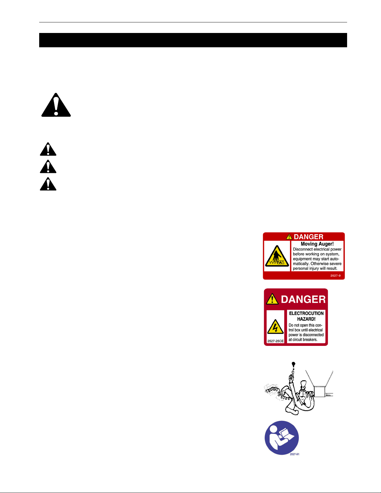
System D utilizes right-hand 90 degree turns. The elevations should be accomplished within the outside elbows.
This system would be recommended over system E since it eliminates additional elbows and left hand turns.
System E uses one additional 90 degree elbow after entering the building. Note that the elbows are left-hand turns.
This system would be improved if the feed bin was moved to the opposite side of the building to provide right-
hand turns instead.
System G represents an extended length system with one additional 90 degree elbow. This is acceptable, but
Systems C or D would be recommended (to reduce excessive run time). Optional equipment required.
FLEX-AUGER® Feed Delivery System Planning
13
MA1032F
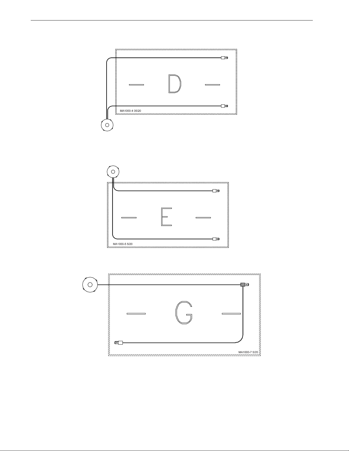
Systems Not Allowed
NOT ALLOWED. System H is not recommended, due to
180 degree, left-hand turns. Erratic auger operation would be
expected. The feed bin should be relocated or an Extension
Hopper should be utilized as in System G.
NOT ALLOWED. System I is not recommended, due to
180 degree, left-hand turns. Excessive elbow wear and
erratic auger operation would be expected. Systems D, E, or
G would be recommended.
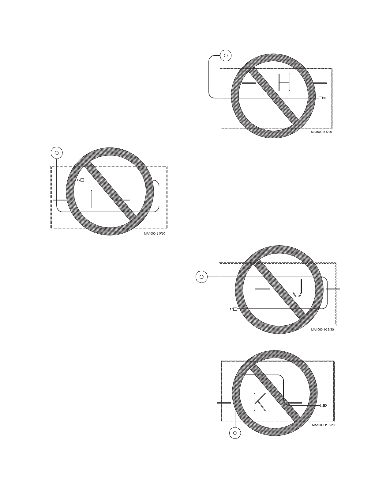
NOT ALLOWED. This system uses 180 degree elbows
and would be subject to premature elbow wear due to
outlet drop placement before an elbow. System C would
be recommended.
NOT ALLOWED. Too many elbows. The result would
be auger vibration, motor stall, and excessive elbow wear.
A twin system, such as C, D, or E, would be
recommended; or an Extension Hopper could be utilized
as in System G.
Planning FLEX-AUGER® Feed Delivery System
14 MA1032F
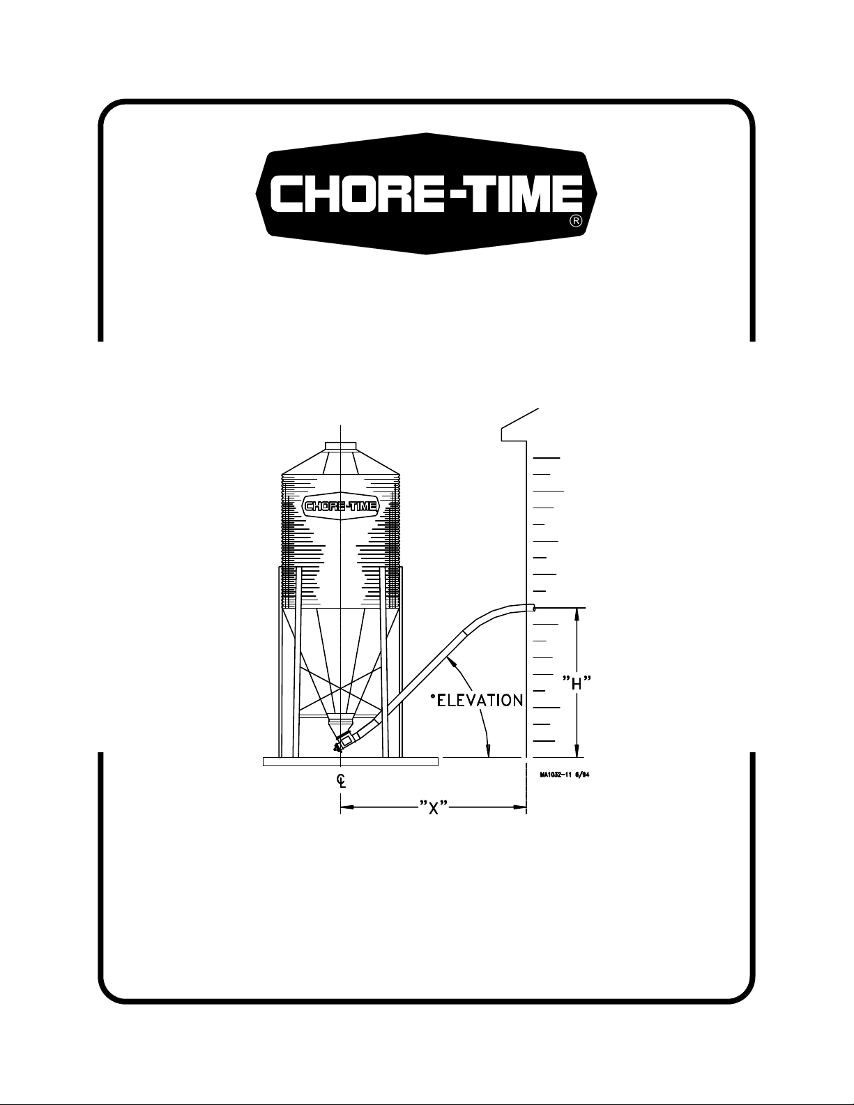
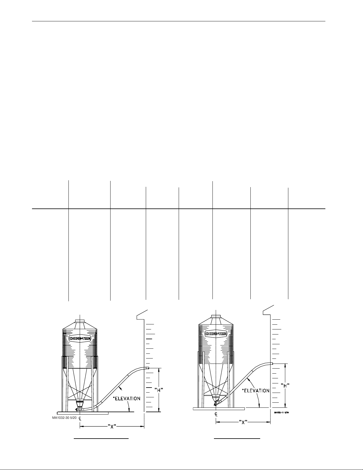
Model 108 Bin Placement Chart
Use this chart to determine the distance from building to center of bin ("X") at the various entrance heights ("H")
and degrees of elevations listed below.
Degree of elevation = Angle at which the system is installed, including the 30 degree or straight-out Upper Boot.
These layout charts are for planning and reference purposes only. A combination of elbows and straight tube may
be required for your installation, depending on the distance from the bin to the building and the height at which
the auger tubes are to enter the building. The elbows may be easily cut to any angle required.
PAY PARTICULAR ATTENTION TO THE MINIMUM DISTANCE BETWEEN THE BIN AND THE
BUILDING.
Many installation and operational difficulties can be avoided if the bin is located farther from the building. If in
doubt, it is BETTER TO BE TOO FAR AWAY THAN TOO CLOSE.
The maximum recommended angle of elevation above the horizontal is 60 degrees. The maximum elevation is 30
feet (9.1 m) . . . if the angle of elevation is no more that 45 degrees.
All systems require adequate support of the auger tubes to prevent sagging and/or excessive forces being
transmitted to the bin boot.
System Model Entrance Height 30 Degree Upper Bin Boot (part no. 4347) Straight-Out Upper Bin Boot (part no. 6093)
"H" 30 Degree 45 Degree 60 Degree 30 Degree 45 Degree 60 Degree
5’ (1.5 m) 9’ (2.7 m) - - - - - - - - - - - - 11.5’ (3.5 m) 10’ (3 m) - - - - - -
6’ (1.8 m) 11’ (3.4 m) 8.5’ (2.6 m) 8’ (2.4 m) 13.5’ (4.1 m) 11’ (3.4 m) 10’ (3 m)
7’ (2.1 m) 12.5’ (3.8 m) 9.5’ (2.9 m) 8.5’ (2.6 m) 15’ (4.6 m) 12’ (3.7 m) 11’ (3.4 m)
8’ (2.4 m) 14.5’ (4.4 m) 10.5’ (3.2 m) 9’ (2.7 m) 17’ (5.2 m) 13’ (4 m) 11.5’ (3.5 m)
9’ (2.7 m) 16’ (4.9 m) 11.5 (3.5 m) 9.5’ (2.9 m) 18.5’ (5.6 m) 14’ (4.3 m) 12’ (3.7 m)
10’ (3 m) 17.5’ (5.3 m) 12.5’ (3.8 m) 10’ (3 m) 20’ (6.1 m) 15’ (4.6 m) 12.5’ (3.8 m)
11’ (3.4 m) 19.5’ (5.9 m) 13.5’ (4.1 m) 10.5’ (3.2 m) 22’ (6.7 m) 16’ (4.9 m) 13’ (4 m)
12’ (3.7 m) 21’ (6.4 m) 14.5’ (4.4 m) 11.5’ (3.5 m) 23.5’ (7.2 m) 17’ (5.2 m) 13.5’ (4.1 m)
13’ (4 m) 23’ (7 m) 15.5’ (4.7 m) 12’ (3.7 m) 25.5’ (7.8 m) 18’ (5.5 m) 14’ (4.3 m)
14’ (4.3 m) 24.5’ (7.5 m) 16.5’ (5 m) 12.5’ (3.8 m) 27’ (8.2 m) 19’ (5.8 m) 15’ (4.6 m)
15’ (4.6 m) 26.5’ (8.1 m) 17.5’ (5.3 m) 13’ (4 m) 29’ (8.8 m) 20’ (6.1 m) 15.5’ (4.7 m)
16’ (4.9 m) 28’ (8.5 m) 18.5’ (5.6 m) 13.5’ (4.1 m) 30.5’ (9.3 m) 21’ (6.4 m) 16’ (4.9 m)
17’ (5.2 m) 30’ (9.1 m) 19.5’ (5.9 m) 14’ (4.3 m) 32.5’ (9.9 m) 22’ (6.7 m) 16.5’ (5 m)
18’ (5.5 m) 31.5’ (9.6 m) 20.5’ (6.2 m) 14.5’ (4.4 m) 34’ (10.4 m) 23’ (7 m) 17’ (5.2 m)
19’ (5.8 m) 33.5’ (10.2 m) 21.5’ (6.5 m) 15.5’ (4.7 m) 36’ (11 m) 24’ (7.3 m) 17.5’ (5.3 m)
20’ (6.1 m) 35’ (10.7 m) 22.5’ (6.8 m) 16’ (4.9 m) 37.5’ (11.4 m) 25’ (7.6 m) 18.5’ (5.6 m)
Distance from center of the bin to the building
Model 108
Straight-Out Boot 30 Degree Boot
FLEX-AUGER® Feed Delivery System Planning
15
MA1032F
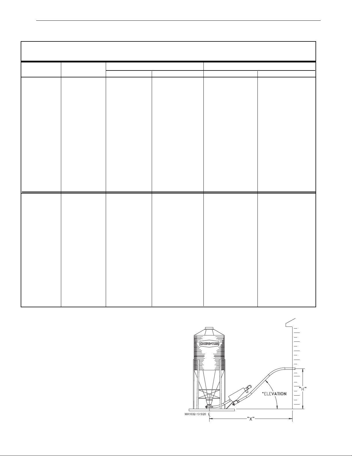
Model 108 Bin Placement Chart (with In-Line or Rotated Screeners)
Chart for minimum distances ("X") from building to center of bin using the various entrance heights ("H"), upper boots and
elevations listed below.
System Model Entrance Height 30 Degree Upper Bin Boot (part no. 4347) Straight-Out Upper Bin Boot (part no. 6093)
"H" 30 Degree 45 Degree 30 Degree 45 Degree
5’ (1.5 m) 12.5’ (3.8 m) 11.5’ (3.5 m) 15’ (4.6 m) 14’ (4.3 m)
6’ (1.8 m) 14’ (4.3 m) 12.5’ (3.8 m) 16.5’ (5 m) 15’ (4.6 m)
7’ (2.1 m) 16’ (4.9 m) 13.5’ (4.1 m) 18.5’ (5.6 m) 16’ (4.9 m)
8’ (2.4 m) 17.5’ (5.3 m) 14.5’ (4.4 m) 20’ (6.1 m) 17’ (5.2 m)
9’ (2.7 m) 19.5’ (5.9 m) 15.5’ (4.7 m) 22’ (6.7 m) 18’ (5.5 m)
10’ (3 m) 21’ (6.4 m) 16.5’ (5 m) 23.5’ (7.2 m) 19’ (5.8 m)
11’ (3.4 m) 23’ (7 m) 17.5’ (5.3 m) 25.5’ (7.8 m) 20’ (6.1 m)
12’ (3.7 m) 24.5’ (7.5 m) 18.5’ (5.6 m) 27’ (8.2 m) 21’ (6.4 m)
13’ (4 m) 26.5’ (8.1 m) 19.5’ (5.9 m) 29’ (8.8 m) 22’ (6.7 m)
14’ (4.3 m) 28’ (8.5 m) 20.5’ (6.2 m) 30.5’ (9.3 m) 23’ (7 m)
15’ (4.6 m) 29.5’ (9 m) 21.5’ (6.5 m) 32.5’ (9.9 m) 24’ (7.3 m)
16’ (4.9 m) 31.5’ (9.6 m) 22.5’ (6.8 m) 34’ (10.4 m) 25’ (7.6 m)
17’ (5.2 m) 33’ (10 m) 23.5’ (7.2 m) 35.5’ (10.8 m) 26’ (7.9 m)
18’ (5.5 m) 35’ (10.7 m) 24.5’ (7.5 m) 37.5’ (11.4 m) 27’ (8.2 m)
19’ (5.8 m) 36.5’ (11.1 m) 25.5’ (7.8 m) 39’ (11.9 m) 28’ (8.5 m)
20’ (6.1 m) 38.5’ (11.7 m) 26.5’ (8.1 m) 41’ (12.5 m) 29’ (8.8 m)
5’ (1.5 m) 11’ (3.4 m) 9.5’ (2.9 m) 11’ (3.4 m) 9.5’ (2.9 m)
6’ (1.8 m) 13’ (4 m) 10.5’ (3.2 m) 13’ (4 m) 10.5’ (3.2 m)
7’ (2.1 m) 14.5’ (4.4 m) 11.5 (3.5 m) 14.5’ (4.4 m) 11.5’ (3.5 m)
8’ (2.4 m) 16’ (4.9 m) 12.5’ (3.8 m) 16’ (4.9 m) 12.5’ (3.8 m
9’ (2.7 m) 18’ (5.5 m) 13.5’ (4.1 m) 18’ (5.5 m) 13.5’ (4.1 m)
10’ (3 m) 19.5’ (5.9 m) 14.5’ (4.4 m) 19.5’ (5.9 m) 14.5’ (4.4 m)
11’ (3.4 m) 21.5’ (6.5 m) 15.5’ (4.7 m) 21.5’ (6.5 m) 15.5’ (4.7 m)
12’ (3.7 m) 23’ (7 m) 16.5’ (5 m) 23’ (7 m) 16.5’ (5 m)
13’ (4 m) 25’ (7.6 m) 17.5’ (5.3 m) 25’ (7.6 m) 17.5’ (5.3 m)
14’ (4.3 m) 26.5’ (8.1 m) 18.5’ (5.6 m) 26.5’ (8.1 m) 18.5’ (5.6 m)
15’ (4.6 m) 28.5’ (8.7 m) 19.5’ (5.9 m) 28.5’ (8.7 m) 19.5’ (5.9 m)
16’ (4.9 m) 30’ (9.1 m) 20.5’ (6.2 m) 30’ (9.1 m) 20.5’ (6.2 m)
17’ (5.2 m) 32’ (9.8 m) 21.5’ (6.5 m) 32’ (9.8 m) 21.5’ (6.5 m)
18’ (5.5 m) 33.5’ (10.2 m) 22.5’ (6.8 m) 33.5’ (10.2 m) 22.5’ (6.8 m)
19’ (5.8 m) 35.5’ (10.8 m) 23.5’ (7.1 m) 35.5’ (10.8 m) 23.5’ (7.2 m)
20’ (6.1 m) 37’ (11.3 m) 24.5’ (7.4 m) 37’ (11.3 m) 24.5’ (7.5 m)
Model 108 using
screener.
Screener Boot is in-
line with system.
Model 108 using
screener.
Screener Boot is
rotated 90 degrees
to system.
Use this diagram and chart to determine proper
feed bin placement when using screener.
"X" = distance from center of bin to where fill system
enters the building.
"H" = height from top of bin pad to where fill system
enters the building.
Degree of elevation = Angle at which the system is
installed (from horizontal).
System shown with screener boot installed in-line; sys-
tem may also be installed with the screener boot
rotated 90 degrees.


Installation FLEX-AUGER® Feed Delivery System
18 MA1032F
Bin Location
For easiest installation and most trouble-free operation, locate the feed bin directly in line with the FLEX-AUGER
System. The layout charts on Page 14 and Page 17 provide some points of reference for bin placement according
to the height at which the system enters the building. The 30 degree or straight-out boots combined with various
elbow hookups offer a wide range of possibilities. The charts are only for reference. Modify and adjust elbows
and tube sections as needed.
NOTE: Two 45 degree PVC elbows are standard with Model 108 FLEX-AUGER Delivery Systems. If additional
elbows are required they must be ordered separately.
The bin collar is installed during bin assembly. Chore-Time bins have a welded collar. Bin Adapter Kits are
available to modify existing bins so that the welded collar can be used. In addition, a Universal Adapter Plate is
available to allow the FLEX-AUGER boot to be installed to other manufacturers’ bins.
Tighten all bin-seal bolts from the nut side. This prevents cutting and "spinning out" of the plastic washer.
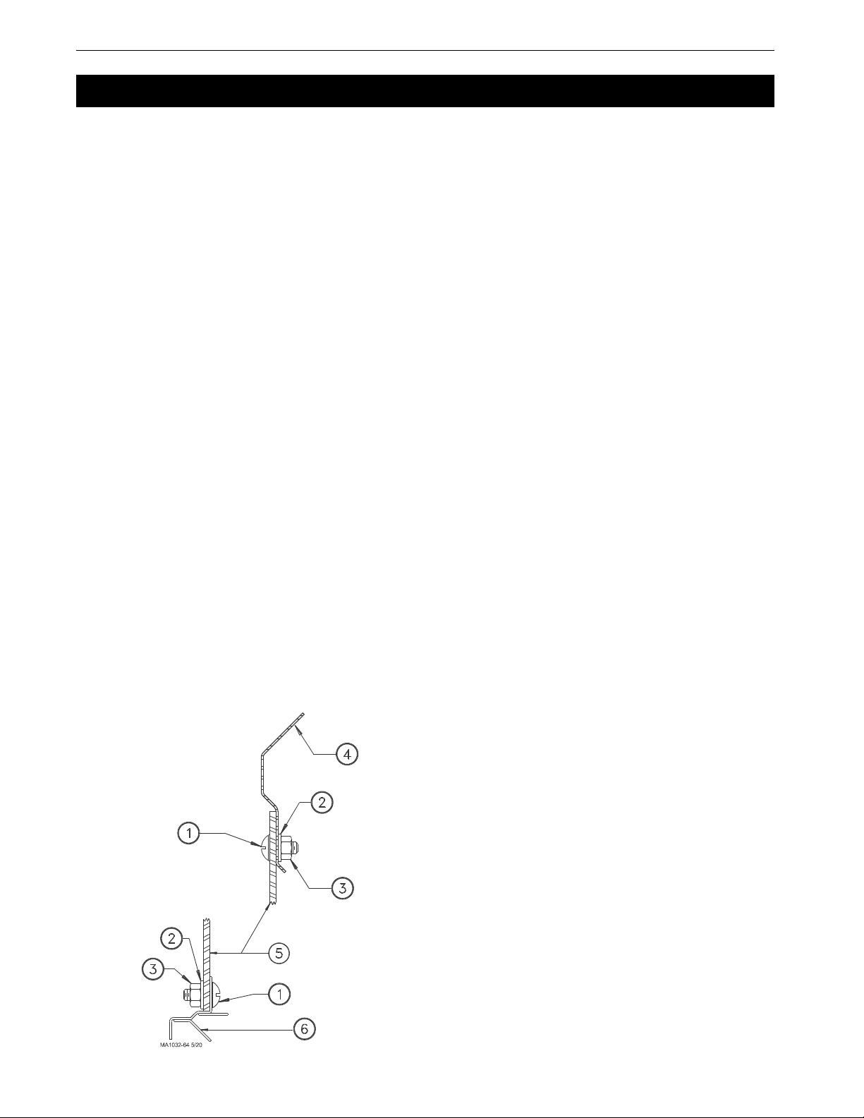
Boot Installation
1.Insert the upper boot into the bin collar and turn it to line up with the direction that the auger line will go. The
boot must be as far up into the opening as it will go. Use the holes in the ring for drilling guides and drill 11/
32" (8.8 mm) holes in the upper rim of the boot. Attach the boot to the bin collar with the hardware provided.
(See Figure 1.)
IMPORTANT: Failure to install the hardware as shown in Figure 1 may cause breakage of the red
boot body.
2.Attach the transfer plate to the upper boot. Use truss head bin-seal bolts installed from the inside of the plate,
with flat washers placed under the nuts.
3.Insert the slide into the transfer plate slot so that it is in its operating position before bolting the slide shield in
place. Remove the paper backing from the sealing strip before fastening the slide shield to the transfer plate.
Use two 5/16-18 x 3/4" hex head machine screws to secure the shield.
4.Bolt the lower boot to the transfer plate using four 5/16-18x3/4" hex head machine screws.
5.After the auger tubes and auger have been installed, attach the 6197 Clean-Out Cover Plate or the optional
Proximity Boot Switch to the lower boot.
Installation
KEY DESCRIPTION PART NO.
1 5/16-18 X 3/4" Truss Hd. MS 7943-1
2 5/16" Nylon Washer 7946
3 5/16-18 Nylon Hex Nut 7945
4 Hopper Collar -
5 Boot Body -
6 Transfer Plate -
Figure 1.Boot Installation Diagram
FLEX-AUGER® Feed Delivery System Installation
19
MA1032F
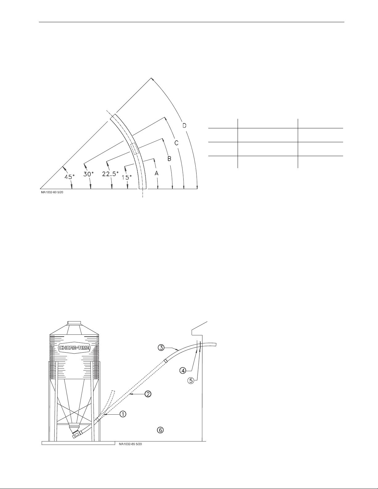
Auger Tube Installation
The FLEX-AUGER Delivery System includes two 45 degree elbows as standard equipment. These elbows are
used to make up the sloping portion of the auger line at the feed bin, and elsewhere in the system if necessary. If
additional elbows are required they should be ordered separately. Figure 2 shows how the elbow can be cut into
shorter sections.
1.Determine where the entrance hole for the auger tube must be located on the building and cut it.
2.If necessary, cut the elbow used where the auger enters the building. Slide the seal ring and neoprene seal
over the straight end of the elbow and place it in the hole cut in the building, with the belled end outside the
building. (See Figure 3.) Clamp the belled end of the second elbow on the outlet end of the boot on the feed
bin.
3.Place the straight end of a tube section inside the belled end of the elbow in the building. Hold the straight
section of auger tube so that it touches the elbow on the boot. Mark the spot where the tube touches the boot
elbow and cut the elbow at that point.
4.Place the belled end of the auger tube over the end of the elbow just cut, and hold the tube against the top
elbow. Mark and cut the straight auger tube so that it will fit between the two elbows.
Remember to cut the auger tube long enough to fit inside the belled end of the elbow in the building.
Figure 2.PVC Elbow Cutting Guidelines
Dimension PVC Steel
"A" 16.8" (43 cm) 16.3" (41 cm)
"B" 25.2" (64 cm) 24.4" (62 cm)
"C" 33.6" (85 cm) 32.5" (83 cm)
"D" 50.3" (128 cm) 48.8" (124 cm)
Note: All measurements are along the outside edge of the elbow.
Note: PVC elbows are belled. Dimensions shown do not include bell.
Figure 3.Elbow Installation outside the building
Key Description
1 45° Elbow
2 Auger Tube
3 45° Elbow
4SealRing
5 Neoprene Seal
6 Note: Belled end of
elbows and auger
tubes should be
towards boot.
Installation FLEX-AUGER® Feed Delivery System
20 MA1032F
Note: In some installations it may be possible to eliminate the elbow on the boot, using only a straight
auger tube and one elbow where the auger tube enters the building.
5.Dry-fit all parts. When satisfied that elbows and tubes fit together smoothly, glue with PVC cement
according to the instructions on cement container and/or on Page 49 of this manual.
6.ALL TUBE JOINTS EXPOSED TO MOISTURE AND WEATHER MUST BE SEALED OR CAULKED
TO WATERPROOF THEM IN ADDITION TO CEMENTING OR CLAMPING THE JOINT.
7.If there are more than 15 feet (4.5 meters) of auger tube between the boot and the building, provide
additional support for the tubes so that the boot does not carry the weight of the auger. Extra support can be
achieved with cables or chain fastened to the bin legs and the auger tube.
8.Locate and cut the outlet holes as required and specified in the instructions on Page 20.
9.Slide (2) Outlet Insert Rings onto the pipe at each outlet hole location.
Each Outlet Assembly is shipped with Insert Rings for both steel and PVC pipes.
The 3/8" (10 mm) thick rings are for steel tube systems. The 1/4" (6 mm) thick rings are for PVC tube
systems. Be sure to use the appropriate Insert Rings for your system.
10.Install the remaining tubes in the system.
The PVC auger tubes should be fastened together using PVC cement.
Model 108 Tube connectors should be used to connect steel auger tubes.
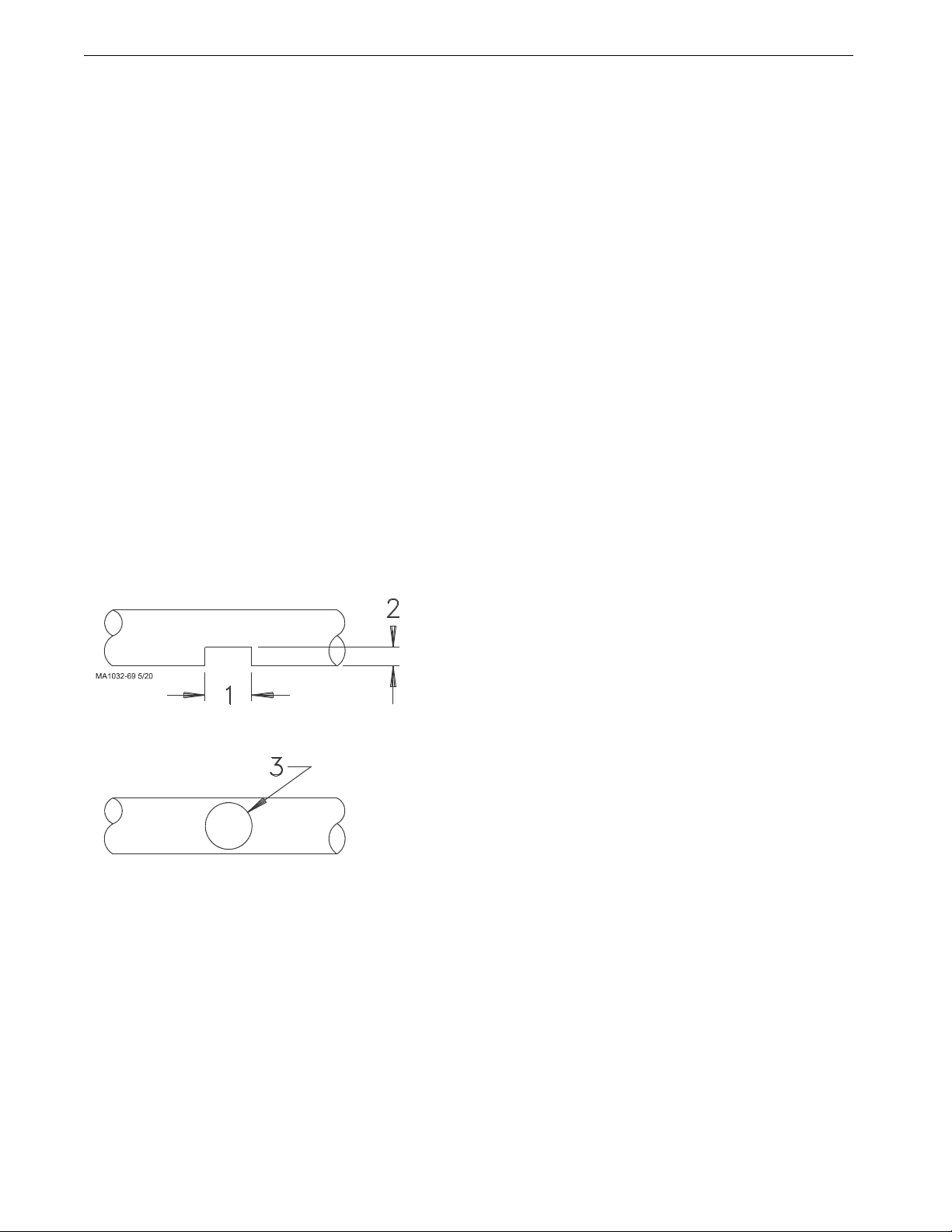
Outlet Drop Installation
Cut the outlet hole in the auger tube. A sabre saw or hacksaw is handy for making the cuts when total feed dropout
is desired. (See Figure 4.) Use a file to remove burrs from opening.
Note: For total feed drop out, outlet holes should be 5-3/8" (137 mm). If some feed carry over is required, outlet
holes should be 3-1/2" (90 mm).
Key Description
1 5-3/8" (137 mm)
2 2" (50 mm)
3 3-1/2" (90 mm)
Figure 4.Outlet Holes provide total or partial feed dropout
Other manuals for 108 FLEX-AUGER
6
Table of contents
Other Chore-Time Industrial Equipment manuals


Popular Industrial Equipment manuals by other brands

Weldability
Weldability ProtectoSmart operating instructions

ProMinent
ProMinent Dulcodes R operating instructions

Leroy-Somer
Leroy-Somer LSA VS 40 Installation and Maintenance

ABB
ABB HT579522 Operation manual

Festo
Festo YSR Series operating instructions

ASTEC
ASTEC JCI LS Series Operation and Service Manual and Parts Book


