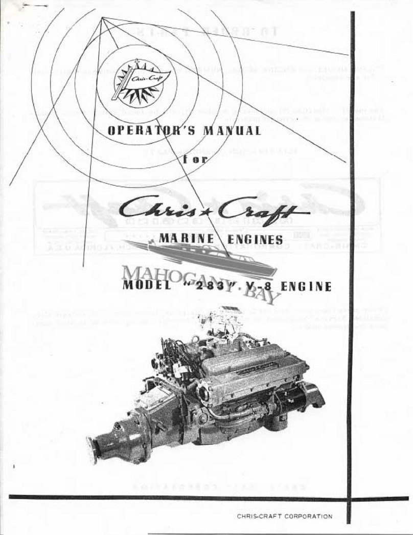
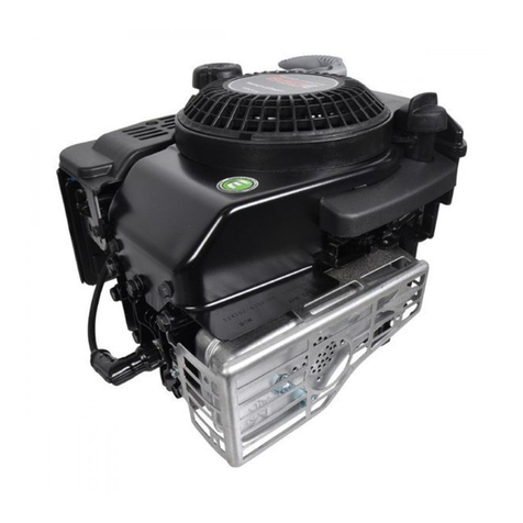
Chris-Craft 283 V-8 User manual

R
eprint
6
September
1
1962
ENGINES
CHRIS
CRAFT
CORPORATION
P O
M
P A N O B E A C H
FL
OR
I
O A
MODEL
283
V
8
ENGINE

TABLE
OF
CONTENTS
TABLE
OF
CONTENTS
1
ENGINE
SPECIFICA
TIONS
2
T
O
OR
DER PAR
TS
3
Adjustment
and
Assembly
Information
3
YOUR
NEW
GHRIS
CRAFT
MARINE
ENGINE
4
Identification
4
Use
Genuine
Factory
Replacement
Parts
4
To
Start
Engine
5
LUBRICATION
SYSTEM
5
Oil
Pressure
Oil
Recommendation
5
To
Change
Engine
Oil
5
Oil
Filter
6
ELEGTRIGAL
SYSTEM
6
Ignition Timing
Ignition
Gircuit
6
Battery
7
Alternator
7
Starting
Motor
7
FUEL
SYSTEM
7
Fuel
R
ecommendation
7
Garburetor
7
Fuel
Pump
g
GOOLING
SYSTEM
g
Water
Temperature
9
Water
Pump
y
VALVES
VALVE TAPPETS
9
REVERSE
GEAR
9
Paragon
Manual
R
everse
Gear
9
10
Manual
Reverse
Gear
Cross
Sectional
View
11
Hydraulic
Reverse
Gear
Cross
Sectional
View
iL
Paragon
Hydraulic
Reverse
Gear
13
ANNUAL
LAY
UP
1314
ANNUAL
FITTING
OUT
MAINTENANCE
SGHEDULE
15
ENGINE
INSTALLATIOI
T
R
ECOMMENDATIONS
16
Mounting
16
Alignment
16
Exhaust
16
R
ecommended
Exhaust
Size
17
Gooling
Water
Intake
17
Engine
Controls
17
Instruments
17
INFORMATION
AYAILABLE
ROTATION
DIAGRAM
18
WIRINC
DIAC
RAM
19
MAJOR
PARTS
OF
GHRIS
CRAFT
V
8
ENGINE
DIAGRAM
20
Page
1

Page 2
MODEL
11283
ENGINE
MODEL
11283
ONLY
ENGINE
SPECLFICATIONS
Horsepower
185
at
4000
RPM
Maximuni
Torque
261
ft
lbs
at
3000
RPM
Carburetion
Single
four
barrel
downdraft
carburetor
MODEL
283M
ONLY
Horsepower
150
at
4000
RPM
Maximum
Torque
228
ft
lbs
at
2600
RPM
Carburetion
Single
two barrel
downdraft
carburetor
COMMON
TO
MODELS
283
AND
283M
Type
4
Cycle
Valve
in
Head
V8
Bore
378
inches
Str
oke
3
inche
s
Piston
Displacement
283
cubic
inches
Revolutions
Sustained
speed
in
excessof
4000
RPM
will
void the
factory
warranty
A
top
cruising
speed
not
in
excess
of
3600
RPM
is
recommended
Weight
Without
Oil
and
Water
283
665
lbs
Approximate
11283
R
15
717
lbs
Approximate
11283
R20
7341bs
Approximate
283
R25
7341bs
Approximate
Nominal
Compression
Ratio
8
01
By
Volume
Minimum
Recommended
Idle
Speed
500
RPM
Oil
Pressure
18
lbs
at
Idle
Approximate
35
to 45
lbs
Maximum
S
peed
hot
Oil
Pan
Capacity
Approximately
5
or
6
qts
Direct
Drive
Capacity
will
vary
with
running
angle
Reverse
Gear
Lubrication
ManualReverseGearlubricatedincommon
with
engine
oil
Hydraulic
Reverse
Gear
lubricated
by
separate
self
contained
Tachometer
Drive
Alternator
Charging
Rate
Gylinder
Numbering
Port
system
SAE
Heavy
for
engines
turning
at
and located
on
top
ward
end
1L
Volt
System
40
R
egulator
Control
Std
or
Opp
Rotation
onehalf
engine speed
of
engine
block
at
for
Amps
Max
Negative
Ground
With
PIo
8
piston
on
Top
Dead
Center
in
firing
position
following
valves
may
be
Stb
d
adjusted
Exhaust
8651
Intake
8742
Crank
engine
one
complete
revolution
with
No
3
pis
on
in
firing
position
and
following
valves
may
be
adjusted
E
chaust
7432
Intake
6531
Firing
Order
Standard
Rotation
15634278
Opposite
Rotation
18724365
Reverse
Gear
End
Std
R
ot
Distributor
Shown
Flywheel
End

Page
3
TO
0
RDER
PAR
T
5
ACNGINE
MODEL
and
ENGINE
SERIAL
NUMBER
must
be
furnished when
repiacement
jSarts
are
required
The
model
designation
and
serial
number
will
be
found
stamped
into
a
plate
fastened
on
top
of
the
exhaust
manifold
ILLUSTRATION
OF
ENGINE
PLATE
DU
ZQs
G3
R1
@
C
00
G
Q
WMEN
OFDERtNG
PARTS
FIRING
ORDER
USE
ONLY
HIGH
GRADI
SPECIFY
MOOEL
AND
OOE
EN61NE
N0
HEAVY
DUTY
MARINE
ENGINE
NUMBER
ENGINE
OIL
5
1E
30
GH
RIS
CRAFT
CORPORA
TIQN
POMPANO
BEACH
FLORIDA
USA
Order
parts
from
your
nearest
Chris
Craft
dealer
or
direct
from
Chris
Craft
Car
poration
Service
Parts
Department
Algonac
Michigan
being
sure
to
furnish
num
jZers
mentioned
above
For
the
best
performance
from
your
engine
INSIST
ON
GENUINE
CHRIS
CRAFT
PAR
TS
ADJUSTMENT
AND
ASSEMBLY
INFORMATION
Dimensions
given
in
inches
Valve
Lash
Engirie
Hot
Intake
Valve
010
Exhaust Valve
020
Distributor
Point
Gap
for
Auto
Lite
Distributor
017
for
Delco
R
emy
Distributor
016
Spark
Plug
Champion
UJ
6
Gap
028
TORQUE
SPECIFIGATIONS
Cylinder
Head
65
ft
lbs
oiled
threads
Connecting
Rod
33
ft
lbs
Main
Bearings
65
ft
lbs
Flywheel
60
ft
lbs
Manifold
30
ft
lbs
Spark
Plug
23
ft
lbs

Page
4
YOUR
MEW
CHRIS
CRAFT
MARINE
ENG1NE
Your
Chris
Craft
Marine
Engine
has
been
delivered
to you
after
a
great
aeal
of
skillful
engineering
careful
manufacture
and
exhaustive
testing
Chris
Craft
s
years
of
practical
experience
in
the
marine
field
are
packed
into
every
engine
leaving
our
plant
With
reasonable
care
during
operation
and
a
minimum
amount
of
maintenance
this
engine
will
deliver
a
maximum
amount
of
dependable
economical
performance
and
long
life
IDENTIFICATION
On
every
engine
there
is
a
plate
on
top
of
the
manifold
giving
the
model
and
s
erial
num
ber
This
information
is
important
and
should
be
included
inall
parts
orders
and
cor
respondence relating
to
the
engine
USE
GENUINE
FACTORY
REPLACEMENT
PARTS
All
Chris
Craft
Marine
Engines
have
special
parts
designed
to
give
the
best
perfor
mance
under
conditions
found
only
in
marine
use
To
insure
long
life
and
dependable
performance
we
strongly
recommend
that
only
factory
replacement
parts
be
uaed
These
may
be
obtained
from your
nearby
Chris
Craft
Dealer
BR
EAK
IN
it
is
very
important
that
the
engine
be
broken
in
properly
All
moving
parts
in
th
engine
are
new
and
have
only
been
run
for
a
few
hours
while
the
engine
had
its
final
test
Engines
must
be
run
carefully
in
the
beginning
until
all
parts
are
worn
in
and
the
engine
becomes
limber
Only
then
will
it
be
safe
to
run
the
engine
fast for
sus
tained
periods
of
time
Running
new
engines
or
engines
after
a
major
overhaul
at
excessively
low
RPM
for
long
periods
should
be
avoided
because
it
will
tend
to
prolong
the
break
in
period
and
delay
proper
seating
of
piston
rings
During
the
first
hour
of
operation
do
not
exceed
2500
RPM
During
the
next
five
hours
operation
do
not
exceed
3200
RPM
During
the
first
six
hours
of
oPeration
running
the
engine
in
excess
of
these
speeds
for
a
minute
at
a
time
to
check
engine
perfor
mance
is
recommended
and
wi21
aid
in
seating
the
piston
rings
An
abnormal
rise
in
engine
temperature
will
indicate
that
the
engine
is
being
run
a
little
too
fast
We
do
not
recommend
a
continuous
speedin
excess
of
3600
RPM
Use
in
excess
of
4000
RPM
voids
the
factory
warranty
During
the
entire
life
of
the
engine
always
run
the
engine
at
medium
speeds
to
allow
the
oil to
warm
up
before
running
at
sustained
high
speeds
When
coming
tothe
dock
after
a
run
always
allow
the
engine
to
run
at
moderate
speed
for
three
to
five
minutes
before
turning
off
the
ignition
This
can
be
done
by
slowing
down
several
hundred
yards
before
you
get
to
the
dock
and
coming
in
slow
or
letting
the
engine
idle
after
you
have
come
into
the
dock
This
is
to allow
the
valves
to
cool
down
while
the
water
is
still
cir
culating
in
the
engine
This
will
help
prevent
warped
valves
TO
START
ENGIIVE
Before
starting
the
new
engine
check
the
oillevel
in
the
crankcase
check
fuel in
tank
and
ventilate
engine
compartment
thoroughly
Shift
the
reverse
gear
to neutral
posi
tion
Open
the
throttle
slightly
approximately
18
open

Page
5
With
ignition
key
turn on
switch
and
engage
the
starter
Do
not
engage
the
starter
for
prolonged
periods
If
the
engine
does
not
start
immediately
investigate
the
cause
of
trouble
As
soon
as
the
engine
starts
release
the
starter
Check
to
make
sure
that
oil
pressure
is
present
and
that
cooling
water
is
circulating
This
engine
is
equipped
with
an
automatic
choke
If
the
engine
does
not
start
due
to
flooding
the
throttle
should
be
opened
fully
which
will
reduce
the
choking
action
The
starter
should
be
engaged
with
throttle
opened
fully
As
soon
as
engine
starts
close
the
throttle
Before
engaging
or
disengaging
the
reverse
gear
it
is
advisable
to
slow
the
engine
down
to
1000
RPM
or
less
Shifting
at
higher
RPM
will
shorten
the
life
of
the
reverse
gear
and
may
cause
damage
LU
BRtCAT10N
SYST
EM
OIL
PR
ESS
UR
E
Form the
habit
of
watching
the
oil
pressure
gauge
Advance
notice
of
serious
trouble
is
nearly
always
indicated
by
the
oil
gauge
Oil
pressure
should
be
approximately
18
lbs
at
idle
speed
and
35
to
45
lbs
at
maxi
mum
speed
with
the
engine
hot
ENGINE
OIL
REGOMMENDATION
Chris
Craft
Marine
Engines
should
be
serviced
with oil of
good
quality
to
insure
smooth
operation
freedom
from trouble
and
best
engine
performance
obtainable
A
Marine
Engine
works
at
maximum
capacity
90 of
the
tizne
while
an
automobile
engine
rarely
works
at
its
maximum
even
10
15
percent
of the
time
Therefore
the
requirements
for
a
good
lubricating
oil
are
far
greater
in a
Marine
Engine
Wz
recommend
the
use
of
S
A
E
430
lubricating
oil
containing
detergents
and
addi
tives
conforming
to
API
designation
MS
or
DG
U
S
MilitarySpec
I
v1IL
L
2104
A
or
supplement
1
or
I
C
E
I
designation
A
or
B
It
is
not
recommended
that
different
brands
of
oiI
be
mixed
Always
replenish
with
the
same
make
and
type
of
oit
that
is
in
the
crankcase
If
it
is
necessary
to
change
the
make
of
oil
always
drain
the
crankcase
as
completeiy
as
possible
before
refilling
TO
CHANGE
OIL
The
new
eng
ine
when
shipped
is
filled
with
S
A
E
10
break
in
oil
After
fifteen
to
twenty
hours
of
running
replace
with
S
A
E
30
motor
oil
and
also
replace
the
filter
element
Subsequent
oil
changes
should
be
made
every
fifty
to
one
hundred
hours
de
pending
on
the
type
of
servi
ce
to
which
the
engine
is
subjected
An
engine
used
for
short
runs
only
will
r
equire
an
oil
change
more
often
than
an
engine
used
for
long
runs
During
the
longer
run
the
oil
attains
the
proper
operating
temperature
thereby
re
ducing
the
po
s
sibility
of c
ontamination
The
best
method
for
removing
crankcase
oil
is
with
a
suction
pump
The
easiest
me
thod
is
to
insert
the
suction
hose
through
the
dip
stick
or
throughthe
14
plugged
hole
on
the
side
of
the
oil
pan
next
to
the
test
rod
hole
Most
marine
service
stations
are
equipped
with
special
pumps
for
removing
oil
or
a
suitable
puznp
may
be
purchased
from
your
Chris
Craft
Dealer
Direct
drive
Model
11283
engines
hold
approximately
five
or
si
c
quarts
of oiL
The
amount
of oil
will
vary
since
engines
are
installed
at
different
angles
in
different
boat
models

Page
6
Manual
Reverse
Gears
are
lubricated
incommon
with
the
engine
and
should
therefore
be
pumped
out
wlien
the
engine
oil
is
removed
To
do
so
remove
the
top
cover
from
the
gear
In
engines
with
Reduction
Gears
one
to
one
and
one
half
quarts
of
oil
will
r
emain
in
the
R
eduction
Gear
after
the
pumping
operation
Hydraulic
Reverse
Gears
have
an
oil
supply
thatis
separatefrom
the
engine
oilsupply
and
therefore
require
individual
checking
and
replacing
We
recommend
the
use
o
Type
A
Hydraulic
Transmission
Fluid
which
should
be
changed
in
the
new
engine
when
the
break
in
oil
is
removed
after
fifteen to
twenty
hours
running
and
thereafter
every
100
hours
or
once
each
season
whichever
comes
first
OIL
FILTER
The
oil
filter
element
should
be
replaced
in
the
new
engine
when
the
break
in
oil
is
removed
after
fifteen
to
twenty
hours
running
Thereafter
replace
the
oil
filter
ele
ment
every
100
running
hours
If
oil
pressure
fluctuates
due
to
a
clogged
oil
filter
reduce
speed
and
cha
nge
the
oil
filter
element
immediately
This
is
a
full
flow
filtPr
which
can
restrict
oil
flow
if
ciogged
with
dirt
even
though
an
oil
bypass
is
incorporated
in
its
design
ELECTRICAL
SYSTEM
The
electrical
equipment
on
the
engine
is
of
Auto
Lite
or
Delco
Rem
inanufa
cture
and
is
guaranteedand
serviced
bythe
manufacturer
Bothmanufacturers
have
official
ser
vice
stations
located
in
important
cities
throughout
the
world
A
directory
of
Auto
Lite
service
stations
may
beobtained
bywriting
directly
to the
Parts
and
Service
Division
Electric
Auto
Lite
Co
Toledo
Ohio
DelcoRemy
service
is
obtained
at
any
United
Motors
Service
establishment
It
is
important
that
all
electrical
connections
be
periodically
inspected
to
make
cer
tain
that
the
condition
of
the
insulation
on
wires
is
good
all
mechanical
connections
are
tight
and
all
connections
are
free
from
corrosion
In
boats
operated
in
salt
water
it
is
especially important
that
all
connections
be
inspected
two
or
three
times
each
year
If
necessary
each
connection
should
be
taken
apart
cleaned
with
fine
sand
paper
given
a
light
coating
of
vaseline
to retard corrosion
and
tightly
reconnected
Battery
terminals
should
be
cleaned
often
with
water
and
baking
soda
coated
with
vas
eline
and
reconnected
High
tension
leads
must
be
in
good
condition
Even
a
small
crack
in
the
insulation
might
permit
oil
or
moisture
to
cause
a
partial
groundrequir
ing
replacement
of the lead
IGNITION
TIMING
To
set
the
ignition
timing
use
a
timing
light
The
flywheel
is
provided
with
a
timing
mark
on
its
rim
and
an
ignition
timing
indicator
is
positioned
over
the
flywheel
ring
gear
With
the
timing light
connected
to
the
battery
and
No
1
spark
plug
port
side
at
flywheel
end
and
the
engine
run
at
idle
500
RPM
set
the
distributor
so
tha
t
the
timing
light
shows
the
flywheel
timing
mark
directly
in
line
with
the
ignition
timing
indicator
Recheck
ignition
timing
after
tightening
the
distributor
to
be
sure
that
it
is
properly
s
et
IGNITION
CiR
CUIT
The
distributor
should
be
inspected
every
100
operating
hours
or
not
less
than
every
six
months
Make
sure
the
vent
hole
in
the
bottom
of
the
distributor
housing
is
kept
open
After
removing
the
distributor
cap
inspect
the
breaker
contacts
If
the
con
tacts
are
grayish
in
color
and
are
not
more
than
slightly
pitted
they
need
not
be
re
placed
We
recommend
that
new
breaker
contacts
be
installed when
required
rather
than
attempting
to
reface
the
old
contacts
h

Page
7
Breaker
contacts
ahould be
set
with
a
gap
of
017
inch
for
Auto
Litc
distributors
and
016
inch
for
DelcoRemy
distributors
The
ignition
timing
should
always
be
reset
using
a
timing
light
Inspect
all
wires
and connections
and
clean
up
any
corrosion
at
connections
if
present
Sparlc
pluge
should
be
cleaned
and
regapped
periodically
Make
certain
there
are
no
cracke
in
the
porcelain
and
that
the
terminals
are
clean
and
tight
Any
spark
plug
which
is
found
to
have
burned
or
badly
worn
electrodes
should
be
replaced
For
model
283
Chris
Craft
Marine
Engines
we
recommcnd
Champion
UJ
6
spark
plugs
and
the
correct
gap
is
028
inch
BATTERY
The
battery
should
be
kept
near
full
charge
To
check
the
condition
of
the
battery
specific
gravity
readings
should
be
taken
For
further
detail
concerning
batteries
consult
your
Boat
Owners
Manual
Also
keep
the
battery
filled
with
pure
water
to the
proper
level
distilled
water
is
best
Never
let
the
level
go
below
the
top
of
the
plates
in
the
battery
ALTERNATOR
GENERATOR
AND
VOLTAGE REGULATIOR
On
generators
make
sure
generator
is
mounted
securely
and
the
generator
belt
is
tightened
so
that
approximately
12
deflection
is
present
The
alternator
or
generator
and
voltage
regulator
should
always
be
of
the
same
make
and
should
only
be
adjusted
and
repaired
by
Auto
Lite
or
Delco
Remy
United
Motors
Service
stations
which
have
instruments
and
information
necessary
to
correctly
re
pair
these
units
On
alternators
check
drive
belt
tension
and
alignxnent
carefully
particularly
after
installation
of
new
belts
Retightening
new
belts is
very
often
necessary
after
a
few
hour
s
NOTE
If
the
alternator
fan
can
be
rotated
by
pulling
on
a
fan
blade
with
one
finger
the belt
is
too
loose
and
must
be
tightened
STARTING
MOTOR
Make
certain
the
starting
motoris
mounted
securelyand
the
Bendixdrive
is
freefrom
dirt If
the
Bendix
drive
accumulates
gummy
deposits
these
should
be
cleanedusing
kerosene
and
a
brush
After
cleaning
apply
10
engine
oil
sparingly
to
thearmature
shaft
and
screw
threads
The
starting
solenoid
should
be
clean connected
securely
and
operating
properly
FU
E
L
SYSTEM
CAUTION
F
UEL
R
EQUIR
EMENT
The
gasoline
recommended
for
Chris
Craft
Marine
Engines
is
a
Marine
leaded
fuel
but
must
have
a
minimum
octane
rating
of at
least
92
research
method
When
Marine
white
gasoline
is used
the
same
above
octane
rating
is
recommended
and
it
is
also
recommended
to
occasionally
use
marine
leaded
fuel
particularly
in
new
engines
or
after
overhaul
CARBURETOR
The carburetor
is
guaranteed
and
serviced
by
the
manufacturer
and
his
distributors
Check
the
carburetor
name
plate
for
manufacturer

Page
8
It
is
important
that
all
fuel
connections
be
kept
tight
and
that
dirt
be
kept
out
of
the
carburetor
Periodically
clean
the
carburetor
flame
arrestor
and
empty
any
deposit
out
of
the
fuel
filter
sediment
bowl
The
carburetors
are
equipped
with
non
adjustable
high
speed
jets
which
require
no
attention
The
idle
adjusting
needles
should
be
turned
to the
position
in
which
the
engine
idles
smoothest
FUEL
PUMP
V
The
fuel
pump
mechanical
or
electrical
with
which
your
engine
is
equipped
is
war
ranted
by
the
manufacturer
who
produced
it
l
Electric
fuei
pumps
will
often
click
or
buzz
when
the
ignition
switch
is
turned
on
This
is
inherent
in
their
operation
COOLING
SYSTEM
The
model
283
engine
is
equipped
with
a
dual
water
pump
The
two
sections
of
the
pump
direct
water
equally
to
each
bank
of
cylinders
insuring
proper
cooling
water
di
stribution
Cooling
water
is
pumped
first
into
the
exhaust
manifolds
where
it
is
preheated
to
re
duce
rapid
temperature
change
and
possible
condensationafter
beingrouted
to
thecyl
inder
block
The
cooling
water
after
traveling
the
full
length
of
the
exhaust
mani
folds
and
back
again
is
routed
into
the
rear
end
of the
cylinder
block
The
water
flows up
around
the
cylinder
bor
es
and
into
the
cylinder
heads
After
cooling
the
valve
areas
in
the
cylinder
heads
the
water
passes
out
of
the
front of the
heads
and
is
con
ducted
to the
after
end
of
the
engine
through
separate
overflow
passages
in
the
mani
folds
It
leaves
the
engine
traveling
through
the
exhaust
tube
where
it
helps
keep
the
exhaust
tube
cool
and
helps
to
muffle
engine
noise
OVER80ARD
rn
x
rn
xr
r
Z
N
C
O
D
r
z
D
O
v
r
OVERBOARD
v
DUAL
WATER
PUMP
OIL
COOLER
HYDRAULIC
ONLY
MODEL
283
WATER
INLET
SCOOP
STRAINER
WATER
COOLING
SYSTEM

Page 9
WATER
TEMPERATURE
A
water
temperature
gauge
when
installed
offers
immediate
assurance
that
the
water
passages
are
free
of
obstructions
and
the
water
pump
is
operating
properly
Since
the
two
banks
of
the
engine
have
separate
cooling
systems
it
is
necessaryto
have
two
gauges
or
warning
devices
for
each
engine
Normal
water
temperature
readings
will
range
between
115
to
150
depending
on
the
temperatur
eof
the
water
entering
the
engine
WATER
PUMP
Ear1y
model
283
engines
were
equipped
with
a
rubber
impeller
pumP
A
bronze
gear
pump
identified
by
grease
cup
on
housing
is
currently
used
Both
type
pumps
are
equipped
with
a
water
seal
which
is
automatic
in
action
If
leak
occurs
around
shaft
this seal
should
be
replaced
A
rubber
impeller
pump
can
often
be
repaired
by
replacing
the
rubber
impellers
Re
pair
can
be
made
by
rexnoving
and
dismantling
pump
The
bronze
gear
pumP
with
grease
cup
requires
little
lubrication
Turn
the cup
one
revolution
each
time
oil
is
changed
In
an
emergency
a
worn
pump
can
be
primed
by
turning
the
cup all the
way
down
forcing
grease
around
the
pump
gears
A
worn
pumP
can
often
be
repaired
with
new
parts
however
if
the
housing
is
worn
a
new
pump
should
be
obtained
Cooling
water
hoses
should
always
be
kept
tight
If
seasonal
inspection
shows
them
to
be
soft
or
deteriorated
they
should
be
replaced
YALVES
AND
VALVE
TAPPETS
Good
valve
action
is
very
important
to
the
efficiency
and
smoothness
of the
engine
The
need
for
valve
grinding
will
irst
be
indicated
by
loss
of
engine
speed
increased
fuel
consumption
and
rough
idling
A
check
of
the
compression
in
each
cylinder
is
a
reliable
check
of
valve
condition
Engines
operated
with
proper
care
will
require
a
minimum
amount
of
valve
vaintenance
In
the
new
engine
check
valve
clearance
after
ten
to
twenty
hours
of
operati
on
Valves
should
be
checked
every
100
hours
of
operation
and
anytime
thehead
is
removedor
the
head
bolts
are
adjusted
Clearance
adjustments
should
be
made
while
the
errgine
is
hot
Intake
valve
clearance
should
be
4L0
L
and
exhausfi
valve
clearance
should
be
02011
REVERSE
GEAR
PARAGON
MANUAL
REVERSE
GEAR
OPERATION
The
reverse
gear
is
very
simple
to
operate
With
the
control
lever
ahead
forward
drive
will
be
engaged
and
with
the
lever
in
the
middle
the
gear
will
be
in
neutral

Page
12
HF
2
HYDitAULIC
REVERSE
GEAR
i
HF
7
HYDRAULIC
REVERSE
GEAR
95 30 29
37
3
41
39
75 69
71
4
66
68
I
81
83
72
74 70
4
21
102
22
10
pp
25
105
40
10
I
20
15
20
16
63
t
115
35
v
18
g
62
94
LL34
96 33
97
61
101
99
98
g
secna
14
3
4
I
8
I
9
7
11 1
17
24
60

Page
13
PARAGON
HYDRAliLIC
REVERSE GEAR
The
actual
operation
of
the
hydraulic
reverse
gear
is
nearly
the
same
as
the
manual
reverse
gear
except
that
hydr
ulic
pressure
does
the
work
in
shifting
gears
The
hydraulic
section
of
the
reverse
gear
is
completely
contained
within
the
reverse
gear
housing
For
the
forward
drive
no
adjustment
is
needed
For
the
reverse
drive
there
is
an
ad
justment
on
the
outside
of
the
starboard
side
of
the
reverse
gear
housing
If
the
gear
slips
in
reverse
drive
remove
the
long
acorn
nut
covering
the
adjustment
screw
Loosen
the
locknut
and
with the
reverse
gear
in
neutral
position
and
the
engineidling
tighten
the
adjustmen
t
screw
until
the
propeller
shaft
just
begins
to
turn
Then
loosen
the
adjustment
screw
14
turn
tighten
the
locknut
and
replace
the
long
acorn
nut
The
Hydraulic
Reverse
Gear
has
an
oil
supply
separate
from
the
engine
and
must
be
checked
and
replaced
individually
Hydraulic
fluid
should
be
changed
once
each
sea
son
or
every
100
operating
hours
whichever
is
first
The
level of the
hydraulic
fluid
sh
uld
reach
the
full
mark
on
the Reverse
Gear
dip
stick
When
adding
or
replacing
fluid
always
use
Type
A
Automatic
Transmission
Fluid
wNNUa
Y
uP
In
areas
where
freezing
is
a
problem
preparing
the
engine
becomes
a
major
consil
eration
because
of the
potential
damage
from
freezing
This does
not
infer
that
lay
ups
in
more
temperate
climates
are
less
important
and
therefore
less
exacting
A
thorough
lay
up
operation
will
include
the
following
steps
1
Drain
the
engine
oilandrefill
the
crankcase
Add
Ghris
Craft
Crankcase
Oil
Supplement
catalog
number
56
00
20630
in
the
proportion
of
16
ozs
for
every
four
to
six
quarts
of
oil
2
Before
lifting
the
boat
from
the
water
add
Chris
Craft
Fuel
Conditioner
and
Valve
Lubricant
partnumber
56
00
20629
to
the
gasoline
supply
in
the
proportion
of
6
oz
to
each
7
gallons
of
gasoline
W
e
suggest
running
the
fuelsupplylow
atthe
end
of
the
season
therebyreducing
the
required
amount
of Fuel
Conditioner
If
preferred
the
treated fuel
may
be
fed
from
anauxiliary
tank
An
outboardmotor
gasoline
tankwould
serve
very
well for this
purpose
Run
the
engine
for at
least
fifteen
minutes
to
dis
perse
the
Conditioner
throughout
the
engine
The
conditioning
properties
lie
in
the
residue
resulting
from
the combustion
of
the
Fuel
Conditioner
therefore
it
is
very
important
to
run
the
engine
as
directed
During
this
final
running
close
the
fuel
valves
at
the
tanks
and
run
the
engines
un
til
they
stall
3
R
emove
and
clean
the
sediment bowls
and
replace
them
4
Drain
the
entire
cooling
system
and
flush with
fresh
water
This
is
es
pecially
important
for
boats
operated
in
salt
water
Drain
plugs
painted
red
and
other
critical
drainage
spots
are
located
as
follows

Pag
e
14
a
On
each
side
of
the
block
just
above
the
oil
pan
and
midway
from
front
to
back
These
openings
are
sometimes
blocked
with
sediment
and
mayre
quire
probing
with
awire
to
d17slodge
the
obstruction
b
In
the
bottom
of
the
water
pump
body
After
removing
this
plug
and
dis
connecting
the
pump
inlet
operate
the
starter
momentarily
thereby
re
volving
the
pump
rotor
and
emptying
each
water
pocket
c
In the
bottom
of
each
exhaust
adapter
which
is
located
in
the
aft
end
of
the
exhaust
manifold
d
Disconnect
the
water
lines
at
the
water
pump
outlet
e
Drain
the
lines
running
from the
through
hull
water
intake
to
the
water
pump
inlet
In
some
installations
these
lines
become
a
water
trap
f
On
283
engines
if
equipped
with
a
hydraulic
reverse
gear
remove
or
disconnect
the
water
lines
between
the
water
pump
and
the oil
cooler
and
remove
the
plug
in
the
bottom
of
the
oil
cooler
g
In the
bottom
of
the
generator
housing
at
the
commutator
end
5
Pull
the
boat
out
of
the
water
bow
first
to
insure
complete
drainage
of
the
exhaust
pipe
and
the
muffler
If
the
boat
is
lifted
vertically
the
same
re
sult
can
be
accomplished
by
keeping
the
bow
higher
than
the
stern
6
Remove
the
battery
or
batteries
and
arrange
to
have
them
chargedperiod
ically
throughout
the
inactive
period
An
uncharged
battery
will
become
damaged
Wash
the
exterior
of
each
battery
with
a
baking
soda
solution
to
remove
all
traces
of
corrosion
and
acid
7
Plug
or
tape
the
exhaust
pipes
to
prevent
moisture
from
entering
valve
cham
bers
during
storage
8
Seal
the
flame
arrestor
against
dirt
and
moisture
This
can
be
done
by
placing
masking
tape
on
the
top
faces
or
by
using
an
airtight
plastic
bag
in
which
to
enclose
the
entire
carburetor
9
Cover
the
fuel
tank
thr
ough
hull
vent
and
the
gascap
vent
making
them
air
tight
10
Repaint
blemished
areas
with
Chris
Craft
blue
engine
enamel
which
is
available
in
handy
Spray
On
cans
11
Apply
a
film
of
Chris
Craft
Oil
Supplement
on
all
exposed
unpainted
metal
surfac
es
12
Remove
the
distributor
cap
and
oil
the
advance
mechanism
Apply
a
light
coating
of
Chris
Craft
Oil
Supplement
to
the
distributor
points
and
the
cam
Replace
the
distributor
cap

Page
15
ANNUAL
FfTTING
OUT
1
Replace
all
drain
plugs
and
re
connect
all
hoses
loosened
during
the
lay
up
cycle
2
Replace
and
re
connect
the
battery
or
batteries
making
certain
they
are
adequately
charged
and
filled
with
water
3
R
emove
plugs
from
the
exhaust
pipes
4
Remove
covering
from
carburetor
or
flame
arrestor
5
Uncover
fuel
tank
vent
and
gas
cap
vent
6
Remove
excess
oil
from
internal
distributor
parts
7
Do
not
run
engine
before
launching
Rubber
impeller
blades
in
water
pump
will
be
damaged
8
Start
the
engine
See
Page
4
for
starting
instructions
MAINTENANCE
SCHEDULE
The
following
maintenance
schedule
is
offered
as
a
suggestion
only
Maintenance
requirements
will
vary
according
to
the
engine
usage
Each
time
the
engine
is
run
Measure
oil
level
in
engine
and
in
reverse
gear
if it
is
the
hydraulic
type
Check
fuel
level
Make
sure
cooling
water
is
circulating
after
starting
engine
Battery
water
should
be
brought
up
to
level
every
one
or
two weeks
Every
50
hours
running
Change
oil
every
50
to
100
hours
depending
on
type
of
service
Clean
carburetor
flame
arrestor
Clean
any
dirt
out of fuel
filter
bowl
Clean
ventilating
valve
located
near
carburetor
each
time oil is
changed
Distributor
3
to
5
drops
medium
engine
oil
in
oiler
at
side
of
base
Correct
any
general
fuel
or
water
leaks
Every
100
hours
running
or
not
less
than
every
6
months
Change
Hydraulic
Reverse
Gear
oil
if
engine
is
so
equipped
Clean
and
tightly
re
connect
all
dirty
electrical
connections

Page
16
Replace
deteriorated
rubber
hoses
Replace
oil
filter
element
every
100
running
hours
Remove
distributor
cap
and
distributor
rotor
Put
5
drops
medium
engine
oil
on
felt
at
top
of
center
shaft
under
rotor
Put
1
drop
of
light
engine
oil
on
breaker
arm
pivot
pin
Wipe
off
excess
Put
light
film
of
grease
on
breaker
cam
Wipe
off
excess
Examine
condition
of
ignition
breaker
con
tacts
and
set
gap
to
proper
dimensions
Exarnine
spark
plugs
Clean
or
replace
plugs
which
are
dirty
or
show
evi
denc
eof
burning
Set
ignition
timing
using
a
timing
light
Align
engine
using
feeler
gauge
at
engine
coupling
Readjust
valve
clearance
to
compensate
for
normal
wear
Adjust
reverse
gear
Examine
condition
of
engine
paint
Aerosol
Spray
Paint
of
blue
engine
enamel
is
available
for
touchup
E1alCIr
IE
INSTALLATION
RECOAARAENDATIAIVS
MOUNTING
A
rigid
bed
should
be
prepared
for
mounting
the
engine
Heavy
wood
engine
string
ers
running
fore
and
aft
in
the
boat
with
proper
cutouts
for
mounting
the
engine
sup
ports
are
usually
used
ALIGNMENT
Proper
alignment
with
the
propeller
shaft
is
important
for
engine
efficiency
and
smoothness
The
two
coupling
faces
one
on
engine
and
one
on
shaft
must
be
paral
lel
Use
a
feeler
gauge
or
piece
of shim
stock
not
more
than
003
inch
in
thickness
When
coupling
faces
are
brought
together
by
hand
not
bolted
the
003
feeler
should
be
tightly
gripped
at all
points
around
the
edges
of
the
couplings
Alignment
must
be
correct
when
couplings
are
viewed
from
the
side
as
well
as
when
seen
from
the
top
It
is
necessary
to
lift
lightly
on
the
shaft
and
coupling
to
compensate
for
the
weight
of
those
two items
but
be
very
careful
that
only
the
weight
is
lifted
and
the
shaft
is
not
sprung
To
adjust
any
misalignment
the
corners
of
the
engine
may
be
raised
or
lowered
by
using
tapered
cast
iron
wedges
In
addition
the
rear
engine
mounts
are
designed
to
permit
lateral
alignment
EXHAUST
The
cooling
water
overflow
is
routed
into
the
exhaust
tube
directly
out
of
the
exhaust
manifold
The
flow of
water
through
the
exhaust
tube
will
cool
the
exhaust
and
in
ad
dition
will
help
to
quiet
the
exhaust
noise
We
recommend
that
copper
tubing
exhaust
hose
or
iron
pipe
of
proper
diameter
be
used
for
the
exhaust
pipe
Copper
tubing
can
be
bent
as
needed
to
fit
a
particular

Page
17
installation
or
can
be
welded
giving
the
required
angles
Be
sure
to
use
correct
diameter
exhaust
pipe
and
keep
bends
to
a
minimum
to
insure
least
amount
of
ex
haust
restriction
possible
RECOMMENDED
EXHAUST
SIZ
ES
Model
283
dual
exhaust
21
2
I
D
each
Model
283
single
exha
ust
31
2
I
D
each
If
both
a
muffler
and
an
exhaust
deflector at
the
end
of
the
tube
are
used
4
exhaust
size
will
be
required
We
strongly
recommend
the
use
of
standard
Chris
Craft
exhaust
elbows
for
connec
ting
from
the
exhaust
manifold
to
copper
tube
or
exhaust
hose
water
cooled
exhaust
systems
The
exhaust
elbows
are
designed
to
give
minimum
back
pressure
and
are
easy
to
install
COOLING
WATER
INTAKE
The
dual
water
pump
requires
two
inlet
hoses
34I
D
hose
which
will
not
col
lapse
easily
should
be
used
Dual
34
intake
thru
hull
fittings
may
be
used
or
a
neat
installation
can
be
made
using
a
single
Ghris
Craft
04
11
23093
intake
scoop
and
a
Chris
Craft
04
11
68912
Y
fitting
dual
hose
adapter
ENGINE
CONTROLS
Various controls
will
have
to
be
connected
to
the
engine
All
linkages
should
be
made
strong
enough
to
withstand
any
strain
to
which
they
will
be
subjected
and
di
rect
positive
action
is
necessary
in
all
connections
Keep
play
at
a
minimum
With
manual
reverse
gears
a
hand
lever
may
be
mounted
directly
on
the
reverse
gear
cross
shaft
or
a
remote
control
can
be
linked
through
suitable
bell
cranks
and
pipe
connections
to
the
engine
With
hydraulic
reverse
gears
suitable
push
pull
controls
may
be
installed
Full
travel
through
the
control
lever
range
must
be
present
at
the
engine
Suitable
throttle
controls
skiould
be
installed
and
connected
to
the
proper
carburetor
arms
Make
sure
that
the
throttle
on
the
carburetor
will
open
andclose
all
theway
All
switches
should
be
resistant
to
rust
and
corrosion
for marine
use
They
shoiild
be
connected
as
shown
in
the
wiring
diagram
INSTRUMENTS
An
oil
pressure
gauge
tachometer
arid
ammeter
should
be
installed
A
fitting
is
provided
an
each
engine
at
top
front for
an
oil
pressure
gauge
In
the
same
local
ity
a
fitting
is
provided
for
the
attachment
of
a
tachometer
drive
cable
The
cable
is
driven at
one
half
engine
speed
and
a
suitable
tachometer should
be
used
Some
tachometer
cable
installations
will
require
a
90
angle
adapter
at
the
enKine
The
ammeter
should
be
wired
into
the
electrical
circuit
as
detailed
on
the
engine
wiring
diagram
If
desired
temperature
gauges
or
warning
indicators
mayalso
be
installed
There
are
threaded
holes
suitable
for
the
insertion
of
temperature
gauge
senders
on
both
sides
of
the
engine
iri
the
Y
s
between
the
manifolc
anc
c
lincic
r
head

Page
18
ItVFORMATION
AVAILABLE
We
are
in
a
position
to
offer
engineering
assistance
to
all
who
are
operating
Chris
Graft boats
or
who
are
making
Ghris
Craft
engine
installations
If
you
wish
gener
al
data
or
information
concerning
an
individual
problem
send
us
full
deta
ils
We
will
be
happy
to
give
a
propeller
size
suggestionbased
on
our
experience
to
improve
present
performance
or
for
a
new
insta
llation
R
QTATION
DIAGRAM
Standard
ChrisCraft
En9in
Installation
SINGLE
SGREW
TWIN
SCREW
Flywheel
Turns
Counter
Clockwise
when
viewed
from
Forward
End
Flywheel
ond
FZing
Gear
Formerly
Marked
S
Now
Marked
L
Flywheel
Turns
Clockwise
when
viewed
from
Forward
End
ywheel
and
9Zing
Gear
was
Formerly
1Jarked
C
Now
Marked
R
Standard
R
ota
i
on
Engine
Tranaom
RIGHT
HAND
PROP
WHEEL
Opposite
I I
Standard
Rotation
Rotation
Engine
Engine
Transom
A1
V
01
LEFT
HAND
RIGHT
HAND
PROP
WHEEL
PROP
WHEEL

NOTE4
1
DO
NOT
eCAL
W011K
TO
DIMGISIOW
3
LIMIT9
ON
ALL
IRACTION
I
DIM
N
IONS
4
OO
UNLY
O
OTX
RWIH
CIII6O
LIMITI
ON
ALL
DCGIMAL
DIM6H6IONS
OO
UNLlJY
OTHlR
W
I6SPGI
IID
4
AvoIo
vewswL
wrtwucrioMS
e
nerzw
ro
M
iwL
ePccincwnoN
sHerr
IR IN
DOUBT
ABOUT
MATil1iAL
8PlCIIILG
e
werowr
enrtowe
wHO
ir
iH
oouar
CON6U
T
HN01NL6flIN0
06
ARTM
NT
TH19
PRINTlUF
PII
OA
ALLlRINT
PqCV
10U6TO
LAT
8T
ALT
NATION
DAT
FLYWHEEL
END
FLYwHEEL
END
5
1
STROKE
AS
SHOWN
CONNECTN
l
HIGH
TEIVSION
TERMINAL
RED
BOOT
D
STRIBUTOR
W
TH
NQl
SPARK
PLUG
THEN
ROTATE
CLOGKW
FROM
N
l
TERM
NAL
ON
DISTRIBUTOR
AND
CONNECT
EACH
HIGH
TENSION
W
RE
TO
THE
RESPECTII
E
SP
4RK
PLUG
DEPEND
NG
ON
THE
FlRING
ORDER
ALTERN
aTOR
GIRCU
T
2f
Z
ro
ioFr
86A
10Fr
ro
20F
6GA
2Or
7O
30Fr
4ca
30F7
To
45
Fr
2GA
45f7
TO
6SF7
I
GA
TO
E
VGI
uE
ALTERNATOR
DISTRIBUTOR
CO
L
BATTERY
SPECIF
CAT
ONS
FOR
STARTING
AND
ORERATIN
ENGINE
ONLY
SAE
2SH
EXTRA
COLD
CAPACITY
60AMP
HOUR
11
PL
4
TE
b
w
uc
co
icN
swrrcH
OPT
O
V
4L
CIRCU
T
FOR
USE
OF
SEP
4RATE
STARTER
AND
lGIV
OPPOS
TE
ROTAT
ON
STANDARD
ROTAT
ON
F
R
VG
ORDER
18724365
F
R
NG
ORDER
15634Z78

Page20
TYPICAL
ENGI
IVE
SHOWItdG
NIAJOR
PARTS
COMPANION
F
ELBOW
ADAPT
THR
E
ARRESTOR
iAUST
MANIFOLD
Iv11NG
INDICATOR
ADJUSTABLE
R
UBBER MOUNT
FRONT
COVER
OIL
FIL
TER
AUTOM4TSC
GHOKE
LACFiOIviETER
GABLE
COtiNECTICiN
bIZ
STARTING
OTOR
FLYWHEEL
FUEL
FILTER
n
LIFTING
RING
PROP
SHAFT
GOUPLING

V
r
y
c
s
v
Q
I
ijW
rl
V
P
QMP
XNp
g
E
ACH
N
CHR15
CRAFT
CQRPoRA
ZVroILDE
W
RS
O
MOTOR
AI
DIs
LARGEST
B
fLORtDA
BppTS
Other manuals for 283 V-8
1
This manual suits for next models
1
Table of contents
Other Chris-Craft Engine manuals
Popular Engine manuals by other brands

VOLTRIUM
VOLTRIUM Offroader Series owner's manual

Graco
Graco XL 10000 Instructions and parts
Grizzly
Grizzly H5377 Wiring diagram
Yamaha
Yamaha MX360 Service manual

Siemens
Siemens MASTERDRIVES MC 1FK7 Configuration manual

Briggs & Stratton
Briggs & Stratton 290000 Series Operating & maintenance instruction manual
