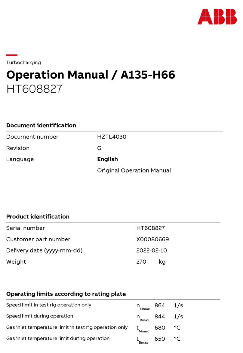
Chris-Craft 307-Q User manual


are
required.
The
modef
designation
('%)
and
serial
number
(':')
will
be
found
stamped
into
a
plate
fastened
ontop
of
the
exhaust
manifold.
k
5E
0lJL.Y
HtGH
GRAD1
WHEN
ORDERING
PARTS
FIRING
QROER
EAVY
DUTY
MARINE
SPECIFY
MODEL
AN0
*
*
*
*
..--..--
ENGINE
NUMBER
CHRIS
-
CRAFT
CORPORBaTCO
Order
prts
from
your
nearest Chris
-
Craft
dealer
or
direct
from
Chris
-
Craft Corporation,
Service
Parts
Department,
Algonac,
Michigan
being
sure
to
furnish
numbers
mentioned
above.
For
the
besf
perfurmance
from
your
e~gh
-
INSIST
ON
GENUINE
CHRIS
-
CRAFT
PARTS
Instructions,
specifa'cations
land
illustrations
shown
are
in
accordance
with
experience and
producf
information
as
developed
a#
time
of
publi-
cation.Tbe
rigb#
is
reserved
to
make
changes
at
any
time
witbout
notice.
SERV1CE
YOU
AFT
SERVICE
A
-
@

I.
.
29
...
7
.*.
3
Mounts
n
.
I
*
*
.
.
=
*
‘
.
.
BELT,
~~~~~~~~~~
Bearings
......
Block,
Cylinder
...
......
......
......
OtLCO&ZLER.
.........
.*.
6
.
.
D
22
*
. .
13
.
‘
E
13
‘
. .
22
...
7
‘
.
.
38
fAPJ.OfL
...........
Pistons
.............
Plugs
.
”
.
s,
II
,
*
’.
.
”
0
Points
.............
Pump,
Circulating
........
Purnp,Fuei
...........
Pump,QiI
. .
=
.
*
*
.
*
,
Purnp,Seawater
.........
CAMSHAFT
.
.
I
Cap.
.......
Carburetor
.....
Condensor
I
*
.
.
Crankshaft
.
I
.
coil..
......
CQUplings
.
= =
.
......
.r.,.r
.I..*.
......
***..I
..L.*.
~A~~~~~~~V~
.
Dipstick
. .
,
.
,
Distributor
.
=
.
.
.*.ld.
......
......
RfSERS
............
Rods,
Connecting ........
STARTER’
...........
Shunt..
...........
.
s
.21
s..
3
...
1
ELBOWS,
EXHAUST
Engine
Assembly
.
.
Engine
Specifications
.
......
......
5..<.r
TACHOMETERDRIVE
......
T
herm
ostat
...........
Timing Chain
Cower
.....
..
...
19
c..13
*.
.
*
2
I..
7
...
8
I
.36,37
FILTER,FUEL
. .
Filter,
Oil.
.....
Firing Order.
.
I
.
.i
Frywheel
......
Flywheel Cover
...
Fresh
Water
Cooling.
.
*.-.*.
......
V
-
DRIVES.
..........
Valves
.............
Vent
Valve
...........
Voltage
R
egu
fator
........
......
......
......
..
4,
38
...
38
..
r
4
GASKETSETS
.
.
Gear,
Reverse
....
Ground,
Electrical
.
I
.
.
I
*“.
......
......
WIRING
............
.
*
I15
HEA5,CYLIMDER
I
.

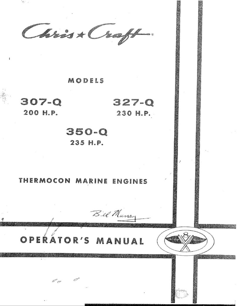
307Q
Series
327Q
Series
4
Cycle
-
v
-
8
E
N
I
N
'
Displacement
307
327
350
1~
Horsepower
200
230
235
__
~ ~
-
COMPRESSION
150
psi
SPARK
PLUG
AC
Mf?
43
T
Champion
UJ
-
6
AC
MR
43
T
GAP
.028"
l[d
Point
Dwell
28
li
Point
Gap
.02Of'
i
Arm
Spring
Tension
19
-
23
ounces
ld
Condenser
.18-.23
microfarad
P
0
Timing
10
.~
MAXIMUM
TORQUE
297
@
3000
RPM
328
@
3200
RPM
323
@
3200
RPM
STROKE
3
%"
3.48
"
NOMINAL
COMPRESSfON
RATIO
8.0:
I
8.8:l
8.5:
1
IDLE
SPEED
500
RPM
OIL
PRESSURE
10
Ibs.
@
Idle
OIL
CAPACITY
6
to
7
qts.
FIRING
ORDER
RH
1-5-6-3-4-2-7-8
FIRING
ORDER
LH
1-8-7-2-43-6-5

6
3
0
adjustment
is
made
by
backing
off
the adjusting nut (rocker arm stud
nut) until there
is
play
in
the
valve
push
rod
and
then tightened to
just
remove
ail
push rod to
rocker
arm clearance.
This
may
be
determined
by
rotating push
rod with fingers
a5
the nut
is
tightened. When rod does not readily
move
in
relation
to
the rocker arm, the clearance
ha5
been
eliminated.
The
adjusting
nut
should
then
be
tightened an additional
1
turn
to
place the
hydraulic
lifter
plunger
in
the
center
of
its
travel,
No
further adjustment
is
required.
With
the
engine
in
the
number
8
firing
position
as
determined
above,
the
following
valves
may
be
adjusted.
3074-327Q-3504
exhaust
8-6-54
intake
8-7-4-2
I
307QL-327QL-350QL
exhaust
2-4-74!
intake
1-5-6-8
Crarik the engine
one
revolution.
This
is
number
3
firing
position.
With
the
engine inthis position. the
following
valves
may
be
adjusted.
307Q-327Q
-
3504
exhaust
7-4-3-2
intake
6-5-3-1
307Qt-327QL
-350
Qt
exfaa~st
1-3-56
intake
2-3-4-7
Q
I

Code
No.
7
8
9
10
,
Par&
No.
16.1
l-lQ042
16.1
1-lOO57
16.
f
1
-
10032
16.11
-
10033
16-1
1-10049
16.1
1-10053
16.1
1-00438
16.1
1-00439
16.1
1-00462
16.74
-
10000
16.74
-
1000
1
16.1
1-00090
I
f
3
10
1
NO.
Weq'd
Name
ST
1
EngineAssembly
-
Stripped
3074-307QA
R.W.
Rot.
I
EngineAssembly
-
Stripped
307QL-307QL-L.H.
Rot.
1
EngineAssembly
-
Stripped
327Q-327QA
R.H.
Rot.
1
EngineAssembly
-
Stripped
327AL-327QAL
R.H.
Rot.
EngineAssembly
-
Stripped
350Q-350QA
R.H.
Rot.
16.1
I-00318
3
16.58-17982
2
16.58-10016
2
16.47-00007
2
16.1
1
-
00086
2
16.
1
1-00093
2
16.1
1-00092
4
16-
1
1-00086
X
-
Engine Assembly
-
Stripped350QL-350QAL
L.H.
Rot.
NOTE:
Stripped
Engine
Assembly
-
includes
a
complete
cylinder
block
assembly
with
crankshaft, camshaft, connecting
rods,
pistons
and
timing
gears
instailed.
Cylinder Bbck
Assembiy-307Q-307QA
Series
C
I
y
i
n
de
r
B
I
oc
k
Ass
e
rn
b
I
y-3
2
7
Q
-
3
2
7
Q
A
Series
Cylinder
BIock
Assembly-350Q-350QA
Series
NOTE:
Clyinder
Block
Assembly
includes fitted
pistons,
ring
assemblies
and bearings.
Cup
plugs
1%''
Brass
Cup
plugs
3%"
Brass
(rear
of
block
below
LH
water
inlet)
Cup
piugs
%"
(oil
galleries)
Cup
plugs
2%''
(camshaft
front
bearing
hole)
Piug
llhf'Sq.
Socket
(water
jacket)
327
Series
Pipe
Plug
%"
Slotted
Head
(oil
pressure
hole)
Pipe
Plug
Ih"Sq.
Head
(oil
galleries)
Valve
Drain
%/'
Brass
(water drain
-
each side)
Elbow,
St.
45%"
MPT
Dowel Pin
%''.x
78"
(align
timing
chain
cover
to
block)
Dowel
Pin
54"
x
78''
(at
oil
pump
flange)
Dowel Pin
%''
diameter (align front
cover)
Dowel
Pin
5/16"
x
9/16"
(at
cylinder
deck)
Dowel
pin
l/qrP
x
?Gf'
(cylinder
block
to
front
bearing
cap)

Code
No.
1
2
3
4
5
6
7
8
9
10
11
12
13
14
15
16
17
18
19
20
23
21.
22
23
24
25
Pa
t-t
No.
16.44-48419
16.4
1
-
5.0005
I6.36-1QOO9
16.50
-
90095
16.50
-
90096
16.20-05432
16.30-00202
16.42-00007
16.93
-
05808
16.2
1
-06260
16.4
I
-05840
16.3~-OOOQ6
16.30
-
00533
16.42
-
00003
16.42
-
00005
16.20-08363
16.3O-OO202
16.30
-
00222
16.42-OOOO7
1:
6.72-07801
16.93-05808
16.2
1-06260
16.42-05840
1
6.39
-
00006
16.30-00533
16.42-00003
16.4
1-00005
16.70-06358
16.30-0OL
27
I6.4~-OOOQ4
16.36-OUOO
5
No:
Weq'd
k
1.
2
1
1
2
4
4
2
2
2
2
2
2
2
2
2
2
4
2
2
2
2
2
2
2
2
2
2
2
2
Name
CT
Grounding Stud
(leftside
enginesthru
fuel
pump
mounting
flange)
Washer
2%ff
X
'1/16"
l/ns
Nut
W-24
Brass
GASKET
SET
Complete
Gasket
Overhaul
Set
307Q-327Q
(Reduction
Gear
Gaskets
must
be
ordered
separately
when
required)
Complete
Valve
Grind
Gasket
Set
FRONT
ENGINE
MOUNTS
Engine
Mount
Bracket
Capscrew
%"---l4
x
llh"
Engine Mount
-
Rubber
Engine
Mount
Housing
Engine Mount
Retaining
Washer
Locknut
5/8"--11
Capscrew
%6''-18
x
2
"
Lockwasher
%"
Plain
Washer
9/16''
Loc
kwa
she
r
%6'
REAR
ENGINE
MOUNTS
(WITHOUT
V-DRIVE)
Engine Mount Support
Capscrew
7/1df-14
x
flh"
Capscrew
7/r6"-14
x
2Y2"
Lockwa
she
r
Wf
Engine Mount
Stud
Engine Mount
Engine
Mount
Housing
Engine
Mount
Retaining Washer
Locknut
%'f-l
1
Capscrew
%6''---l8
x
2
"
Loc
kwas
her
%d'
Plain
Washer
2!/64'f
NOTE:
The
following
items
are
attached
to
the
rear
engine
supports
Lifting
Ring
Capscrew
Gff-24
i(
Il/S"
Lockwasher
3h"
I~CX
Nut
%"---24

Code
No.
34
35
36
37
38
39
40
41
42
43
44
45
26
27
28
29
30
31
32
33
Pa
rt
No.
16.20
-
00093
16.30-00202
16.30
-
00124
16.20
-
08610
16.44-08267
16.72
-
08268
16.21-08264
16.93-05808
16.57
-
07660
16.4
1-05840
16.39
-
00006
16.30-00546
16.42-OOOI2
16.36
-
07694
16.42-OO012
16.70-06358
16.73-08245
16.73
-
08266
16.3O-OO214
16.42-OUUO7
16.20-086
10
16.30-00
135
No.
Req'd
2
4
2
2
2
2
2
4
2
2
2
2
2
6
4
2
4
2
8
8
2
8
Name
Bracket,
Engine
Support
Screw.
Cap
Hex
Head
%"--I6
x
1"
Bracket
Engine
Mount
Support
Engine
Mount
Adjusting
Stud
Engine
Mount
Retaining
Shaft
Engine Mount
V
-
Drive
Housing
Rubber
Engine
Mount
Engine Mount
Spacer
Washer
Engine
Mount
Retaining
Washer
Engine
Mount
Retaining
Nut
%"-11
Capscrew
%"---16
x
1%''
(Engine Mount
Housing)
Hex
Nit-Adjusting
Stud
Lac
kwas
he
r
Lifting
Ring
(attach
one
to
each
Eng.
Mount
Support
Brkt.)
Screw,
cap
bk?x
Head
%6"-----4
X
1%"
tockwasher
%"
E
~~~~~~
(WITH
%DRIVE)
NOTE:
Should
show
mounts
used
(w/V
drives) before
engine
#307-
Engine
Mount
Support
Spacer
Reverse
Gear
&
V
-
Drive
Support
Capscrew
f/;6"-14
x
2
"
Lockwasher
7/16"
Engine
Mount
Support
Bracket
Capscrew
%"-24
x
1%"
214834W
16.36
-
00005
8
Hex
Nut
%"---24
16.42-OOOO4
8
Loc
kwasher
34''

Page
6
Code
Part
NO.
NO'
1
16.11-00338
16.11
-
00339
2
16.11-00141
3
16.
I1
-00142
4
16.11-00143
6
16.
I
1-00046
7
16.1
~00030
8
16.1
1-OOO45
9
15.11-00086
9(a)
16.11-00207
No.
Req'd
Name
1
1
'I
2
2
I
1
I
1
3
CAMSHAFT
Camshaft
Assembly-307Q,
327Q,
3504
RH
Rot.
Camshaft Assembly-307QL,
327QL,
350QL
LH
Rot.
Camshaft Rear Bearing
Camshaft Front
&
Rear Inter
-
Bearing
Camshaft Front Inter
&
Center Bearing
Camshaft Sprocket-307Q,
327Q,
350Q,
RH Rot.
Camshaft
Gear-307Q. 327Q,
350Q,
LH
Rot.
CamshaftTiming
Chain--307Q,
327Q,
350Q
RH
Rot.
Camshaft
Dowel
Pin
(incl.
in
Camshaft
Assembly)
Camshaft
Gear
or
Sprocket
Bolt
%6"---18
x
3h"
NOTE:
See
end
of front
cover
section
for
Camshaft
thrust screw.
NOTE:
It
is
very important
that
special
camshaft.
lubricant
be
applied
liberally
to prevent
damaging
camshaft
lobes
when
new
camshaft
or
valves
are
installed.
This
lubricant
can
be
ordered from Chris
-
Craft
using
part
number
56.00-20630.

9
I
-
Code
No.
10
3%
12
13
14
15
15
16
17
17
17
17
17
1.7
17
17
17
18
19
20
21
22
23
24
25
26
27
28
Pa&
Ma.
16.1
1
-
00348
16.11-00283
16.11
-
00506
16.14
-
00096
7.6.3.
I
-
00028
f
6.1
1-00334
16.1
1
-
00098
16-51
-
1OO27
16.5
f
-
1
0016
16.31-00389
16.
I.
1-OO327
16.1
1-00390
16.1
l-QO3W
16.
P
1-00392
16.1
f
-
00393
16.11
-
00395
f
6.11-00396
16.11-00397
16.11-00398
16.1
LOO375
16.11-00376
16.1
1
-
08290
€6.1
1-00157
16.11
-
00158
16.20
-
08292
16.30
-
0832
1
f
6.20-083
13
16.47
-
06612
16.30-00078
16.42-00002
16.7
1-07809
16.99
-
08334
16.43-00005
28(a)
16.30-0739.2
No.
Req'd
1
1
f
1
€
1
2
2
2
1
4
1
1
1
P
4
4
4
4
4
6
f
6
6
1
6
I
1
4
4
1.
1
5
5
Name
Cran
kshafl
AssembIy-307Q,
307QA
Series
~~~~~
16.11-00348
is
used
for
engine
before
307-103158
Crankshaft
Assembly---327Q,
3.2748
Series
MOTE:
16.11-00283
is
used
for
engines
before
3274-210153
Crankshaft
Assernbfy---350Q,
35OQA
Series
Flywheel
Dowel
Pin
(incf.
in
Crankshaft)
Crankshaft
Gear---307Qt7
307QAL,
327QL,
327QAL,
350QL,
356QAL
Crankshaft
Sprocket----307Q,
307QA,
327Q,
327QA,
350Q,
35OQA
RH
RQ~.
Crankshaft Gear
or Sprocket
Key
Crankshaft
Front
Bearing
Seal
(RH
Rot.
only)
Crankshaft
Front
Bearing
Seal
(LH
Rat.
only)
16.11-00371
is
used
for
engine
after
307-103157
16.1
1-00372
is
used
for
engines
after
3274-210152
LH
Rot.
Main
BearingSet
-
Rear
(tncl.
Upper
&
Lower)
Main
Bearing Set-AII
except
Rear
(Upper
&
Lower)
Main
Bearing
Set
-
Rear
(Inc.
Upper
&
Cower
.001
US)
Main
Bearing
Set
-
Rear
(Incl.
Upper
&
tower
.002
US)
Main
Bearing
Set
-
Rear
(rncl.
Upper
&
Lower
,010
US>
Main
Bearing Set
-
Rear
(Incl.
Upper
&
Lower
-020
US)
Main
Bearing
Set-AII
except
Rear
(Upper
&
Lower
.UO1
US>
Main
Bearing
Set-Aif
except
Rear (Upper
&
tower
,002
US)
Main
Bearing
Set
-
All except
Rear
(Upper
&
tower
-010
US>
Main
Bearing
Set-AII
except
Rear
(Upper
&
Lower
.02U
US)
Main
Bearing
Cap
Bolt
(2
in
ea.
main
bearingap)
Main
Bearing
Cap
Stud
(front,
inter,
Center
&
Rear)
HIEEL,
PULLEY
84
WATER
PUMP
DRIVE
Flywhee!
&
Ring
Gear
Assembly
Attaching
Bolt
Lockwasher
7/16''
Ext.
Shkprf.
Flywheel
Pulley
Flywheel
&
Pulley
Retaining
Bolt
%"-ZU
x
2%"
Water
Pump
Drive
Putley
Pin
-
Water
Pump
Pulley
to
Flywheel
Pulley
Capscrew
%6"--18
x
I
%''
Water
Pump
to
Flywheel
Pulley
Loc
kwas
her
36"
NOTE:
When
replacrng
the
water
pump
drive
pulley
before
serial
numbers
307Q
(102067)
and
327Q
(210370),
the
16.47-06612 pim
water
pump
pulley
to
flywheel
pulley
must
be
removed.
IVE
~
Damper
Drive
Hub-To
Crankshaft
Drive
Plate
Assembiy
(Y-32554)
Special
Lockwasher
%"
External
Ca
psc
re
w
WORLD'S
LARGEST
BefffDPR
QP

Code
No.
Part
No.
16.20
-
08315
16.30
-
00144
16.30
-
00152
16.42
-
00004
16.47
-
00008
16.58
-
10168
No.
Req'd
Name
FLYWHEEL
COVER
Flywheel Cover
Capscrew
%"-16
x
2?h"
Capscrew
%"-16
x
z3h"
Lockwasher
3/8"
Pin Ignition Timing
Indicator
Pipe
Plug
3h"-14
Brass

4
i
PARTS
LIST
-
MODEL
“307Q,
3274
&
350Q”
ENGINES
Page
9
Code
No.
36
37
38
39
40
41
42
43
44
45
46
47
48
49
50
Part
No.
16.20
-
08263
16.58
-
1
0
164
16.50
-
08254
16.30
-
00028
16.30
-
00020
16.30
-
00004
16.30
-
00124
16.42
-
00001
16.42
-
00004
16.72
-
08298
16.30
-
00078
16.43
-
0001
1
16.99
-
08278
16.72
-
08374
16.50
-
00166
16.72
-
08133
1
42
i4
40
No.
Req’d Name
TIMING
CHAIN
COVER
1
Timing Chain Cover
1
1
2
Capscrew
Jj4”--2O
x
21/4”
4
Capscrew
1/4”-Z0
x
1%”
2
Capscrew
1/4‘’--20
x
3/4“
11
Capscrew
3/8”-16
x
1”
8
Lockwasher
1/4
”
11
Lockwasher
3/8”
Pipe
Plug
Countersunk Head
1/2”-14
Brass
Cylinder Block to TimingChain Cover Gasket
TACHOMETER
DRIVE
ASSEMBLY
1
Fuel Pump Drive Adapter
3
Capscrew
5/16“-18
x
1%”
3
Toothlock Washer
5/16”
1
Tachometer Drive Assembly
1
Tachometer Drive Spacer
2
1
Tachometer Drive Cap
Gasket (Between Spacer
&
Cover)
Q

PARTS
LIST
-
MODEL
"307Q,
327Q
&
35UQ"
ENGINES
Page
10
PISTONS,
KINGS,
COSN
ECTIXG
KOLIS
I
Code
Part
No.
1
1
2
3
4
5
6
6
6
6
6
No.
16.11
-
00359
16.11
-
00533
16.11
-
00531
16.11
-
00383
16.11
-
00384
16.11
-
00385
16.11
-
00356
16.11
-
00235
16.11
-
00387
16.11
-
00388
16.11
-
00300
16.11
-
00303
16.11
-
00304
16.11
-
00509
16.11
-
00510
16.11
-
00380
16.11
-
00381
16.11
-
00382
No.
Req'd
8
8
8
1
1
1
8
1
1
1
8
16
16
16
16
8
8
8
Name
PISTONS
AND
RINGS
~
Piston
&
Pin Assembly Before Engine
307Q
-
102992
Piston
&
PinAssembly
3074
Series After Engine
3074-102991
Piston
&
Pin Assembly
3504
Series
Piston Rings
-
Complete Set
3074, 3504,
STD
Piston Rings
-
Complete Set
3074, 350Q-.020
O.S.
Piston Rings
-
Complete Set
307Q,350Q-.030
O.S.
Piston
&
Pin Assembly
327Q
Series
Piston Rings
-
Complete Set
3274
STD
Piston Rings
-
Complete Set
3274
.020
O.S.
Piston Rings
-
Complete Set
327Q.030
O.S.
CONNECTING
RODS
ConnectingRod Ass'y. (Includes rod, bolts, cap
&
nuts)
Connecting Rod Bolt
Connecting Rod Nut
Connecting Rod Bearing
STD
(Includes upper
&
lower halves)
Connecting Rod Bearing-.001 U.
S.
(includes Upper
&
Lower Halves)
Connecting
Rod
Bearing---.002 U.
S.
(includes Upper
&
Lower Halves)
Connecting
Rod
Bearing-.010
U.
S.
Connecting
Rod
Bearing-.020 U.
S.

I
y
P
i
I
I
I
!
i
I
I
I
I
I
I
I
1
*
-
I
I
I
I
PARTS
L!ST-
MODEL
“367Q, 327Q
&
3504”
ENGINES
Page
11
Code
Part
No.
No.
16.20
-
08208
16.51
-
17639
16.50
-
08230
16.50
-
08231
16.30
-
00008
16.30
-
00020
16.30
-
00078
16.30
-
00086
16.42
-
00001
16.42
-
00002
16.70
-
08234
16.39
-
08394
1
6.95
-
08274
16.70
-
08273
16.95
-
08233
16.95
-
08232
16.57
-
5843
2
16.58
-
Z
0057
16.57
-
08397
1
6.57
-
06494
16.72
-
08236
16.50
-
08510
16.72-08285
16.99
-
00008
16.30
-
00120
16.42
-
00004
16.72
-
08238
16.11
-
00070
16.11
-
00274
16.11
-
00011
No.
Req‘d
Name
1
1
1
1
11
3
2
2
14
4
1
6
1
1
1
1
1
2
1
1
1
2
1
1
1
1
1
1
1
1
Oil
Pan
Oil Pan Seal, Front
Oil Pan Gasket, Left
Oil Pan Gasket, Right
Capscrew
%”-20
x
1”
Capscrew
1/4”-20
x
13h”
Capscrew
%6”---l8
x
13h”
Capscrew
%6”-l8
x
2%’’
Lockwasher
%’’
Lockwasher
5/16”
Oil
Pan
Baffle
Locknut
3/”--16
(Oil Pan Baffle to Main Bearing Cap Studs)
Oil Pick
-
UpAssembly (Consist ofthe followingtwo parts:)
Oil Pick
-
Up Support Bracket
Oil Pick
-
Up Screen
&
Tube
Ass’y.
(Consist
of
the followingtwo parts):
Oil
Pick
-
Up Screen Assembly, only
Oil Pick
-
Up Tube
Elbow
34’’
NPT-Between Oil Pick
-
Up
Tube
&
Oil
Pump
Oil Level Dipstick Tube Ass’y. (Consist of the following
two
parts):
Oil Level Dipstick Tube (Not Stocked)
Oil Level Dipstick Tube Collar (Not Stocked)
“0”
Ring
(with Plug)
Plug, Oil Level Dipstick
Tube
inOpposite Side
from
DipstickAssembly
Dipstick Tube Clamp
Capscrew
%“-16
x
3/4”---Atta~h clamp tocylinder
block
Lockwasher
%’’
Oil
Level Dipstick
OIL
PUMP
&
SCREEN
ASSEMBLY
~~ ~
~~_____
Oil Pump
&
Screen Assembly
Attaching
Bolt
%6’’-14
x
2”
Oil
Pump Shaft Assembly (also drives dist.)
WORLD’S
LAR@€ST BUILDER
OF
MBtQf?
BOAT’S

Fage
12
PARTS
LiST-
MODEL “307Q,
327Q
&
350Q”
ENGlNES
13
6
A
-
@
1

-,
I
,
PARTS
LIST
-
MODEL
-=
“307Q,
3274
&
35OQ”
ENGINES
Page
13
Code
NO.
2
3
4
5
G
7
8
9
10
11
12
13
14
15
16
17
18
19
20
21
22
?3
24
25
26
27
Part
No.
16.20
-
08283
16.99
-
08126
16.58
-
10225
16.58
-
1
01
51
16.50
-
08356
16.50
-
0835
1
16.30
-
00082
16.41
-
00002
16.59
-
10580
16.59
-
10117
16.57
-
58420
16.57
-
58421
16.59
-
10580
16.58
-
10213
16.59
-
17989
16.20
-
08330
16.58
-
1015
1
16.72
-
08127
16.72
-
08128
16.81
-
08130
16.70
-
08418
16.30
-
00120
16.42
-
00004
16.30
-
00
132
16.42
-
00004
16.99
-
00074
16.57
-
08426
NO.
Req’d
1
1
1
2
1
1
2
2
1
1
1
1
1
1
1
1
1
1
1
1
1
2
2
1
1
1
1
Name
OIL FILTER
ASSEMBLY
Oil Filter Adapter
-
To Cylinder Block
By
-
Pass Valve Assembly
Reducer Bushing
3/4”
MPT
x
3/”
FPT
Hex Head Pipe Plug
%”-27
NPT
Oil Filter Adapter Ring Gasket
Oil Filter Adapter toCylinder Block Gasket
Capscrew
%”--18
x
2”
Washer Flat
5/16”
Elbow vz’’-T
x
3/8”
MPT
-
Adapter Out
Connector
%”-T
x
36’’
MPT
-
Adapter
In
Oil Line
-
Adapter to Filter Base
Oil
Line
-
Filter Base to Adapter
Bushing
%”
FPT
x
Ihr’
MPT-Into Filter Base
Elbow,
45%’’
T
x
%”
MPT
-
Filter Base Outlet
Oil Filter Base
Pipe Plug
?4”-27
Nipple1%”--16---Attach Oil Filter To Base
Hex
Nut
%”--l6
Oil Filter Assembly (AC-iYPF-24,WIX--#PC55P)
Bracket
-
OilFilter Base to Intake Manifold
Capscrew
36”---16
x
3/”-Atta~h Filter Base
to
ManifoldBracket
Lockwasher
%”
Capscrew
%”-l6
x
1%’’
Loc
kwasher
%”
Tube Clamp
Spacer
-
Between Clamp
&
Cylinder Block
NOTE:
The last four
(4)
parts support and attach
oil
lines
to
the cylinder
Elbow-1/2”
T
x
34’’
MPT
block.
d
WORLD’S
LARGEST
BUILDER
OF
MOTOR
BOATS

I‘
Fage
14
PARTS
LIST
-
MODEL
“307Q,
327Q
&
350Q”
ENGINES
Code
No.
1
1
2
2
Part
No.
16.11
-
00535
16.11
-
00340
16.11
-
00536
16.11
-
00360
16.11
-
00322
16.11
-
001
53
16.11
-
001
52
1
6.1
1
-
0004
1
16.11
-
00273
16.11
-
00433
No.
Req’d
8
8
8
8
16
16
16
8
8
32
Name
VALVES
Exhaust Valve
(301Q
Series)
MOTE:
16.11
-
00255
isused before engine
3074-102992
Exhaust Valve
(3274
Series)
NOTE:
Oversize stems available:
intake Valve
(3074
Series)
NOTE:
16.11
-
00148
is
used before engine
307Q
-
102992
Intake Valve
(3274
Series)
NOTE:
Oversize stems available
Valve Spring
&
Damper Assembly
Valve Stem Oil Shield
Valve Stem
Oil
Seal
Exhaust Valve Rotator Assembly
Intake Valve Spring Cap
Valve Stem Key
16.11
-
00535
is used after engine
3074-102991
16.11
-
00536
is
used after engine
307Q
-
102991
3
i

PARTS
LIST
CI
MODEL
"3074,
3274
&
350Q".
ENGINES
Page
15
.
-
._
r
*
Code
No.
9
10
11
12
13
14
14
14
14
I
15
16
17
48
19
20
21
22
23
Part
NO.
No.
Req'd
Name
VALVE
LIFTERS
&
ROCKER
ARMS
NOTE:
It
is very important that special camshaft lubricant be appfied
liberally to prevent damaging camshaft lobes,
when
new camshaft
or valve lifters are installed. This lubricant can be ordered from
Chris
-
Craft usingpart number
56.00
-
20630.
16.11
-
00399 16
Valve Lilfter Assembly
-
Hydraulic
16.11
-
00038 16
Push Rod
16.11
-
00014 16
Valve Rocker Arm
16.11
-
00043 16
Nut, Valve Rocker, Ball Combination
16.11
-
00227 16
Rocker Arm Stud
%"--24
x
21/2"-.003
0.S.
16.11
-
00228 16
Rocker Arm Studs
.013
O.S.
CYLINDER
HEAD
16.11
-
00664
2
16.11
-
00316
2
16.11
-
00374
2
16.11
-
00343
2
16.50
-
00147
2
.
16.11
-
00010 14
16.11
-
00022
4
16.11
-
00003 -16
.-
16.58
-
10164 4
Cylinder Head
-
Complete with Valves
(3074
Series)
Cylinder Head
-
With Studs
only
(3074
Series)
Cylinder Head
-
Complete with Valves
(3276
Series)
Cylinder Head
-
With Studs only
(327Q
Series)
Cylinder Head Gasket (Stainless Steel)
Cylinder Head Bolt
-
Long
Cylinder Head Bolt
-
Medium
Pipe, Plug, Countersunk Head
1/2"--14
Brass
Cylinder Head Bol-t-Short
. ,>
-.
16.11
-
00457
16.11
-
00543
16.11
-
00532
16.11
-
00161
16.1
1-00259
.
16.11
-
00358
16.92
-
07761
16.92
-
07601
16.92
-
08280
16.92
-
08239
16.92
-
08434
16.92
-
0843
5
16.92
-
08661
16.92
-
08662
16.92
-
08663
16.92-08664
VALVE
COWER
C?
cap opening towards the
30
e
cover with the opening
towards thefront
on
models
307
1
Valve Cover,
LH
1
Valve Cover,
RH
1
2
Valve Cover Gasket
8
Valve Cover Reinforcement
8
Vatve Caver Bolt
1
Fuel Decal
2
Decal, Engine Rotation
(307QL, 327QL,3SOQL)
2
HP
&
Model Decal
(307Q
-
307QL')
2
HP
&
Model Decal
(327Q
-
327QL)
-
'
HP
&
Model Decal
(307QA
-
307QAL)
2
HP
&
Model Decal
(327QA
-
327
2
HP
&
Model Decal
(350QL)
2
HP
&
Model Decal
(3504)
2
HP
&
Model Decal
(350QAL)
2
HP
&
Model Decal
(350QA)
Oil Filter Cap
(In
LH
Valve Cover)
WORLD'S
LARQES7
BUILDPR
OF
MOTOR
BOATS

Page
16
PARTS LIST
-
MODEL
"307Q' 3274
&
3504"
ENGINES
Code Part
NO.
NO.
1
16.95
-
08609
16:20-08608
06.44
-
06310
06.58
-
1
0
167
06.74
-
10007
2
06.50
-
00176
16.30
-
00128
16.30
-
00148
16.30
-
00130
16.30
-
00
132
16.42
-
00004
1
6.70
-
08424
PI
0.
Req'd
1
1
4
1
3
1
5
2
1
2
12
1
Name
INTAKE
MANIFOLD,
FRONT
LIFTING
RING
&
THROTTLE
BRACKET
Intake Manifold
Ass'y
(Incl. the following
4
parts)
Intake Manifold
Studs
Pipe Plug
3/1'r-14
NPT
(Aft
of Carburetor to drain Manifold)
Cup Plug(One aft
of
liftingring&two
aft
of carburetor)
Intake Manifold Gasket Set
Capscrew
%"-l6
x
llhr'
Capscrew
W-16
x
21/2",
%"-16
x
l3/"
Capscrew
%"-16
x
3%''
Capscrew
3/"-16
x
1%"
(Thru
Oil
Filter Base Bracket)
Loc
kwasher
%"
Throttle Bracket
Q

PARTS
LIST
-
MODEL
“307Q, 3279
&
3504”
ENGINES
Page
17
Code
No.
6
7
8
9
10
11
12
13
14
15
16
17
18
19
20
21
22
23
24
25
26
27
Part
NO.
06.82
-
48688
16.96
-
00087
16.70
-
07852
16.50
-
08352
16.36
-
00003
16.42
-
00002
16.82
-
00036
16.32
-
00128
16.99
-
00073
16.41
-
00027
16.4
1
-
00028
16.39
-
000
13
16.50
-
0836
1
16.44
-
08360
16.39
-
00010
16.72
-
36264
16.95
-
0851
1
16.57
-
97584
16.59
-
10705
16.99
-
08329
16.20
-
08495
16.50-083
17
16.30
-
00066
16.42
-
00002
16.20
-
08496
16.50
-
08333
16.30
-
00004
16.42
-
0000
1
06.42
-
00008
NO.
Req’d
1
1
1
1
4
4
1
1
1
1
1
1
1
1
1
1
1
1
1
1
1
1
2
2
1
1
4
4
1
Name
CARBURETOR ASSEMBLY
8t
FLAME
ARRESTOR
Carburetor Assembly
-
Carter AVS
-
6
1
17s
Carburetor Repa
i
r
Kit
Throttle Lever
Carburetor to Intake Manifold Gasket
Hex Nut
5/16”-24
Loc
kwa
s
her
5/16”
FlameArrestor
-
Consisting of the following five
parts:
Round Head Screw
#6
-
32
x
2”
Tube
&
Bracket Assembly
Washer
l%4“
x
%”
x
1/32”
Washer
%4”
x
3&”
x
.050”
t-!ex Locknut
#6
-
32
FlameArrestor to Carburetor Gasket
Flame Arrestor Stud
Flame Arrestor Stud Locknut
Automatic Choke Heater Stove
Automatic Choke Heater Tube
IA’’
OD
x
12”
Automatic Choke Heater Tube Cover
Nu
t
-
Hea ter Tube
to
Ca
rburetor
THERMOSTAT
&
HOUSING
ASSEMBLY
Thermostat
Thermostat Housing
Thermostat Housingto Intake
Manifold
Gasket
Capscrew
%6’’--18
x
1”
Lock
wa
s
h
e
r
5/16”
Thermostat Housing Cap
Thermostat
Housing
Cap Gasket
Capscrew
‘/4”-20
x
3/’’
Lockwasher
‘A’‘
Lockwasher
%”
x
-171
x
-125”
WORLD’S
LARG€Sf
BUILDER
OF
MdfOR
BOATS
Other manuals for 307-Q
1
This manual suits for next models
5
Table of contents
Other Chris-Craft Engine manuals
Popular Engine manuals by other brands

Oriental motor
Oriental motor US Series operating manual
Oriental motor
Oriental motor PKP Series operating manual

Oriental motor
Oriental motor BMU Series operating manual

Ebmpapst
Ebmpapst BCI-63.55 operating manual
Oriental motor
Oriental motor AlphaStep AR Series operating manual
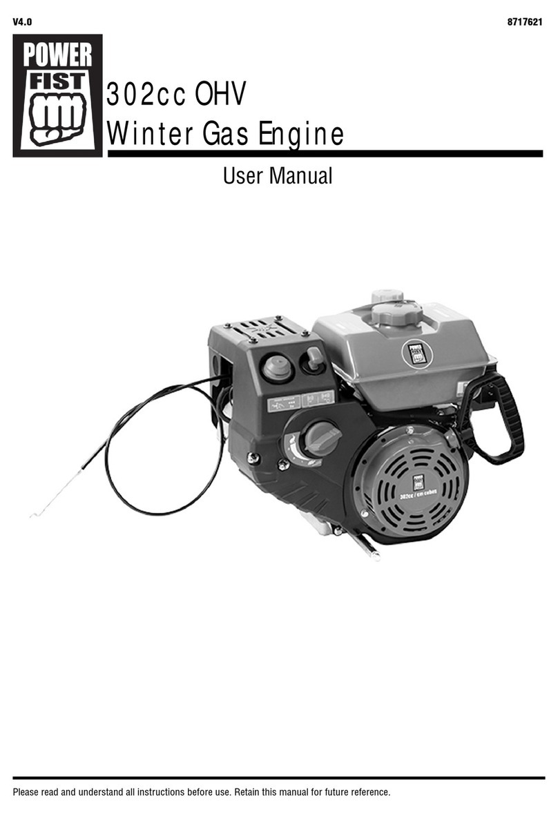
Power Fist
Power Fist 8717621 user manual
WEICHAI
WEICHAI WP4GNA Assembly/disassembly manual

Volvo Penta
Volvo Penta MD 11C/110S Instruction book
Predator Engines
Predator Engines 60340 Owner's manual & safety instructions
LOMBARDINI MARINE
LOMBARDINI MARINE LDW 1404 SD Installation handbook

3W
3W 342i B2 user manual

poclain hydraulics
poclain hydraulics MS 25 manual
