Yamaha MX360 User manual

MX360
SERVICE MANUAL
7HC-F8197-E0
2016_11×2 !
7HC-F8197-E0_cover.indd 1 2016/11/21 14:17:28

7HC-F8197-E0_cover.indd 2 2016/11/21 14:17:28

FOREWORD
This manual was written by the Yamaha Motor
Powered Products Co., Ltd. primarily for use
by Yamaha dealers and their qualified mechan-
ics. It is not possible to put an entire mechan-
ic’s education into one manual, so it is
assumed that persons using this book to per-
form maintenance and repairs on Yamaha
Multi-Purpose Engine have a basic under-
standing of the mechanical precepts and pro-
cedures inherent to Multi-Purpose Engine
repair technology. Without such knowledge,
attempted repairs or service to this model may
render it unfit for use and/or unsafe.
Yamaha Motor Powered Products Co., Ltd. is
continually striving to further improve all mod-
els manufactured by Yamaha. Modifications
and significant changes in specifications or
procedures will be forwarded to all Authorized
Yamaha dealers and will, where applicable,
appear in future editions of this manual.
HOW TO USE THIS MANUAL
PARTICULARLY IMPORTANT
INFORMATION
Particularly important information is distin-
guished in this manual by the following nota-
tions.
This is the safety alert symbol. It is used to
alert you to potential personal injury haz-
ards. Obey all safety messages that follow
this symbol to avoid possible injury or
death.
WARNING
A WARNING indicates a hazardous situa-
tion which, if not avoided, could result in
death or serious injury.
NOTICE
A NOTICE indicates special precautions
that must be taken to avoid damage to the
machine or other property.
TIP
A TIP provides key information to make proce-
dures easier or clearer.
MX360
SERVICE MANUAL
©2016 by Yamaha Motor Powered
Products Co., Ltd.
2nd Edition, November 2016
All rights reserved. Any reprinting or
unauthorized use without the written
permission of Yamaha Motor
Powered Products Co., Ltd.
is expressly prohibited.

HOW TO USE THIS MANUAL
This Service Manual contains general information on service procedure and data for the Multi-
purpose engine. For complete information on service procedure and data, it is necessary to use
this Service Manual together with the Supplementary Service Manual.
Comprehensive explanations of all installation, removal, disassembly, assembly, repair and check
procedures are laid out with the individual steps in sequential order.
9The manual is divided into chapters and each chapter is divided into sections. The current sec-
tion title is shown at the top of each page 1.
9Sub-section titles appear in smaller print than the section title 2.
9To help identify parts and clarify procedure steps, there are exploded diagrams at the start of
each removal and disassembly section 3.
9Numbers are given in the order of the jobs in the exploded diagram. A number indicates a dis-
assembly step 4.
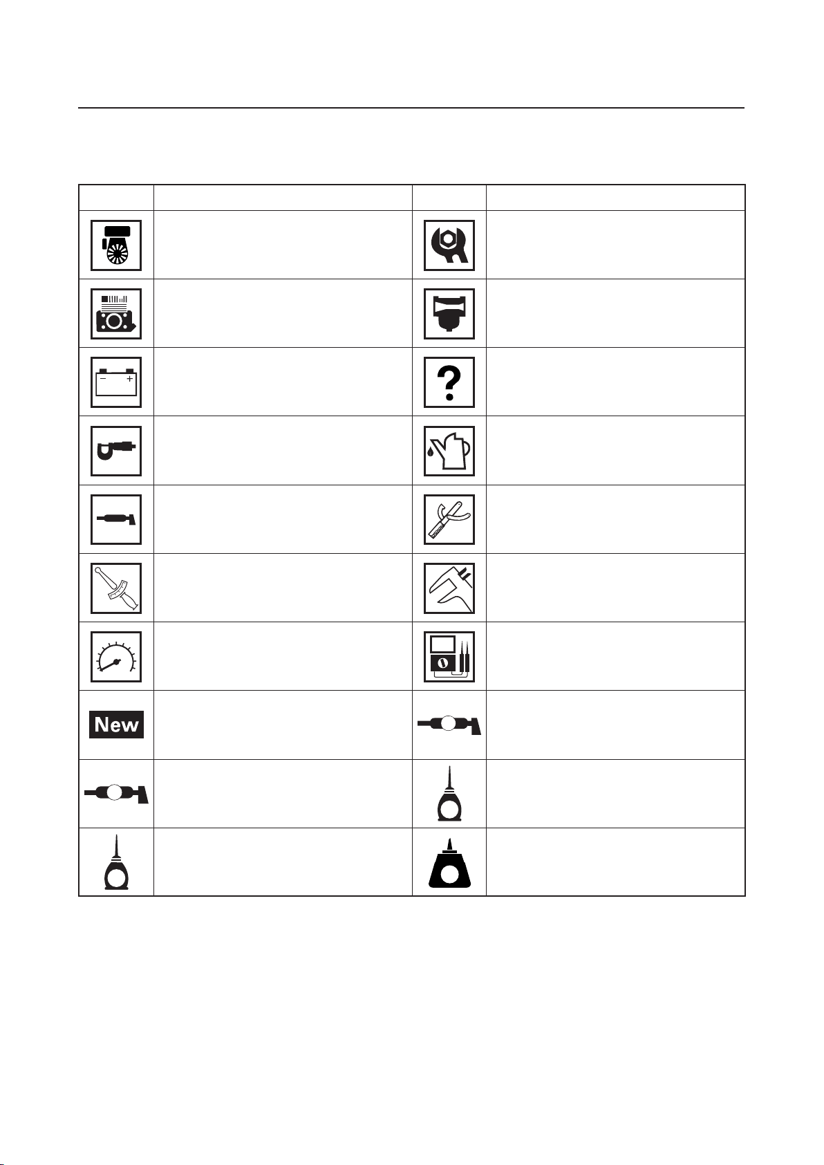
9Symbols indicate parts to be lubricated or replaced 5.
Refer to “ILLUSTRATED SYMBOLS”.
9A job instruction chart accompanies the exploded diagram, providing the order of jobs, names of
parts, notes in jobs, etc. 6. This step explains removal procedure only. For installation, reverse
the steps.
9Jobs requiring more information (such as special tools and technical data) are described
sequentially 7.
9These are general tightening torques for all Multi-purpose engines. Tightening torque specifica-
tions for each model are provided on the Supplementary Service Manual 8.
ENG
3-22
CYLINDER HEAD COVER, CYLINDER HEAD
CHECKING THE PUSH ROD
1. Check:
9 Push rod runout
Runout limit:
Refer to “SPECIFICATIONS” in
the Supplementary service
manual.
Out of specifications → Replace.
CHECKING THE CYLINDER HEAD
1. Check:
9 Cylinder head combustion chamber
Check the combustion chamber for car-
bon deposits.
Any carbon deposits → Eliminate.
TIP
Be sure not to damage the contact surface of
the cylinder.
2. Check:
9 Cylinder head
Cracks/damage around the hole of
spark plug → Replace.
CHECKING THE ROCKER ARM
1. Check:
9 Rocker arm
Wear/damage/cracks → Replace.
1
4
8
3
6
7
2
5
ENG
3-20
CYLINDER HEAD COVER, CYLINDER HEAD
6543
2
78
9
78
11 Nm (1.1 m · kgf, 8.0 ft · lbf)
20 Nm (2.0 m · kgf, 14 ft · lbf)
2.3 Nm (0.23 m · kgf, 1.7 ft · lbf)
12 Nm (1.2 m · kgf, 8.7 ft · lbf)
50 Nm (5.0 m · kgf, 36 ft · lbf)
1st
2nd
7 Nm (0.7 m · kgf, 5.1 ft · lbf)
9
1
Order Job/Parts to remove Q’ty Remarks
Removing the cylinder head cover,
cylinder head
Remove the parts in the order listed.
Fuel tank Refer to “FUEL TANK” on 3-4.
Muffler Refer to “MUFFLER” on 3-6.
Air filter Refer to “AIR FILTER” on 3-3.
Carburetor Refer to “CARBURETOR” on 4-1.
Flywheel cover Refer to “FLYWHEEL” on 3-12.
1 Spark plug cap 1
2 Spark plug 1
3 Air filter case stay 1
4 Cylinder head cover 1
5 Cylinder head cover gasket 1
6 Cylinder air shroud 1
7 Locknut 2
8 Adjuster 2
9 Screw 2
CYLINDER HEAD COVER, CYLINDER HEAD

ILLUSTRATED SYMBOLS
(Refer to the illustration)
SYMBOL DEFINITION SYMBOL DEFINITION
General information Periodic checks and
adjustments
Engine Carburetor
Electrical Troubleshooting
Specifications Filling fluid
Lubricant Special tool
T
R
.
.
Tightening torque Wear limit, clearance
Engine speed Electrical data
Replace the part with a new one. LS Lithium-soap base grease
MMolybdenum disulfide grease
E
Engine oil
M
Molybdenum disulfide oil LT Apply locking agent (LOCTITE®)


INDEX
GENERAL INFORMATION GEN
INFO
PERIODIC CHECKS
AND ADJUSTMENTS CHK
ADJ
ENGINE ENG
CARBURETOR
ELECTRICAL
TROUBLESHOOTING
CARB
ELEC
TRBL
1
2
3
4
5
6

CHAPTER 1.
GENERAL INFORMATION
IMPORTANT INFORMATION ....................1-1
PREPARATION FOR REMOVAL AND
DISASSEMBLY CAUTION ON
SERVICE ..............................................1-1
NOTES ON SERVICE...........................1-1
ALL REPLACEMENT PARTS ...............1-2
GASKETS, OIL SEALS, AND
O-RINGS...............................................1-2
BEARINGS AND OIL SEALS ...............1-2
BASIC SERVICE INFORMATION..............1-3
ELECTRICAL SYSTEM........................1-3
SPECIAL TOOLS AND TESTERS.............1-6
CHAPTER 2.
PERIODIC CHECKS AND
ADJUSTMENTS
INTRODUCTION ........................................2-1
MAINTENANCE INTERVALS CHART ......2-1
PERIODIC MAINTENANCE/
LUBRICATION INTERVALS ......................2-1
PERIODIC MAINTENANCE ......................2-3
SPARK PLUG .......................................2-3
FUEL LEAKAGE ...................................2-5
ENGINE OIL LEAKAGE .......................2-5
ENGINE OIL LEVEL .............................2-5
REPLACING THE ENGINE OIL ...........2-6
AIR FILTER ELEMENT.........................2-7
MUFFLER .............................................2-8
FUEL TANK FILTER..............................2-9
FUEL COCK STRAINER ....................2-10
BREATHER HOSE..............................2-11
CYLINDER HEAD
DECARBONIZATION..........................2-11
ADJUSTING THE VALVE
CLEARANCE ......................................2-12
ENGINE SPEED (WITHOUT
THROTTLE LEVER MODEL) .............2-14
ENGINE SPEED (WITH THROTTLE
LEVER MODEL) .................................2-15
ADJUSTING THE ENGINE SPEED ...2-16
RECOIL STARTER .............................2-17
FITTINGS AND FASTENERS ............2-17
CHAPTER 3.
ENGINE
ENGINE INSPECTION...............................3-1
MEASURING THE COMPRESSION
PRESSURE ..........................................3-1
AIR FILTER ................................................3-3
FUEL TANK................................................3-4
Except for MX360A46A5/
MX360C46A5........................................3-4
MX360A46A5/MX360C46A5 ................3-5
MUFFLER ..................................................3-6
INSTALLING THE MUFFLER ...............3-7
RECOIL STARTER ....................................3-8
DISASSEMBLING THE RECOIL
STARTER..............................................3-9
CHECKING THE RECOIL
STARTER............................................3-10
ASSEMBLING THE RECOIL
STARTER............................................3-10
FLYWHEEL ..............................................3-12
REMOVING THE FLYWHEEL ............3-13
INSTALLING THE FLYWHEEL ...........3-14
INSTALLING THE TCI UNIT ...............3-15
GOVERNOR.............................................3-16
REMOVING THE FLYWEIGHT
SHAFT ASSEMBLY AND
GOVERNOR SHAFT ..........................3-17
DISASSEMBLING THE
FLYWEIGHT SHAFT ASSEMBLY.......3-17
CHECKING THE FLYWEIGHT
SHAFT ASSEMBLY AND
GOVERNOR SHAFT ..........................3-17
ASSEMBLING THE FLYWEIGHT
SHAFT ASSEMBLY ............................3-18
INSTALLING THE FLYWEIGHT
SHAFT ASSEMBLY AND
GOVERNOR SHAFT ..........................3-18

ENGINE SWITCH AND OIL WARNING
UNIT .........................................................3-19
CYLINDER HEAD COVER, CYLINDER
HEAD .......................................................3-20
CHECKING THE ROCKER ARM .......3-22
CHECKING THE PUSH ROD.............3-22
CHECKING THE CYLINDER
HEAD ..................................................3-22
INSTALLING THE CYLINDER
HEAD ASSEMBLY ..............................3-23
VALVE ......................................................3-24
REMOVING THE VALVE AND
VALVE SPRING ..................................3-25
MEASURING THE VALVE AND
VALVE SPRING ..................................3-25
CHECKING THE VALVE SEAT...........3-27
VALVE LAPPING ................................3-29
INSTALLING THE VALVE AND
VALVE SPRING ..................................3-30
PISTON, CAMSHAFT, CRANKCASE,
AND CRANKSHAFT................................3-31
REMOVING THE BALANCER
SHAFT, CAMSHAFT, AND VALVE
LIFTER................................................3-33
CHECKING THE BALANCER
SHAFT ................................................3-33
CHECKING THE CAMSHAFT ............3-33
CHECKING THE VALVE LIFTER........3-35
INSTALLING THE VALVE LIFTER,
BALANCER SHAFT, AND
CAMSHAFT ........................................3-35
CHECKING THE CRANKCASE
COVER ...............................................3-35
INSTALLING THE CRANKCASE
COVER ...............................................3-36
MEASURING THE CYLINDER...........3-36
CHECKING THE CRANKCASE .........3-37
CHECKING THE PISTON AND
PISTON PIN........................................3-38
MEASURING THE PISTON RING......3-40
CHECKING THE CRANKSHAFT .......3-41
CHECKING THE CONNECTING
ROD OIL CLEARANCE ......................3-43
INSTALLING THE PISTON AND
PISTON RING.....................................3-44
INSTALLING THE CRANKSHAFT......3-45
SELECTING THE CRANKSHAFT
SHIM ...................................................3-47
CHAPTER 4.
CARBURETOR
REMOVING THE CARBURETOR..............4-1
DISASSEMBLING THE CARBURETOR ...4-2
CHECKING THE CARBURETOR.........4-3
CHAPTER 5.
ELECTRICAL
ELECTRICAL COMPONENTS..................5-1
SWITCHES.................................................5-2
CHECKING THE SWITCH
CONTINUITY .......................................5-2
IGNITION SYSTEM....................................5-3
TROUBLESHOOTING CHART.............5-3
CHAPTER 6.
TROUBLESHOOTING
ENGINE......................................................6-1

1-1
GEN
INFO
IMPORTANT INFORMATION
SVU1030
SVU1040
SVU1050
SVU1060
SVU1070
SVU1080
SVU1090
SVU1100
GENERAL INFORMATION
IMPORTANT INFORMATION
PREPARATION FOR REMOVAL AND DISASSEMBLY
CAUTION ON SERVICE
1. Fire prevention
When servicing the engine, always keep the engine and your-
self away from fire.
NOTES ON SERVICE
1. Correct tools
Be sure to use the correct special tool for the job to guard
against damage.
2. Oil, grease and seals
Be sure to use genuine Yamaha oils, grease and sealers, or the
equivalents.
3. Expendable parts
Always replace the gaskets, O-rings, cotter pins and circlips with
new parts when servicing engine.
4. Tightening torque
Be sure to follow torque specifications. When tightening bolts,
nuts or screws, start with the largest-diameter fastener and work
from an inner position to an outer position in a crisscross pat-
tern.
5. Notes on disassembly and assembly
a. Parts should be cleaned in solvent and blown dry with com-
pressed air after disassembly.
b. Contact surfaces of moving parts should be oiled when reas-
sembled.
c. Make sure that the parts, move smoothly after each section of
the machine is assembled.
CHAPTER 1.

1-2
GEN
INFO
IMPORTANT INFORMATION
SVU1110
SVU1120
ALL REPLACEMENT PARTS
We recommend the use of genuine Yamaha parts for all replace-
ments. Use oil and/or grease, recommended by Yamaha, for
assembly and adjustment.
GASKETS, OIL SEALS, AND O-RINGS
1. All gaskets, seals, and O-rings should be replaced when an
engine is overhauled. All gaskets surfaces, oil seal lips, and
O-rings must be cleaned.
2. Properly oil all mating parts and bearings during reassembly.
Apply grease to the oil seal lips.
BEARINGS AND OIL SEALS
Install the bearing(s) 1and oil seal(s) 2with their manufacture’s
marks or numbers facing outward. (In other words, the stamped
letters must be on the side exposed to view.) When installing oil
seal(s), apply a light coating of lightweight lithium base grease to
the seal lip(s). Oil the bearings liberally when installing.
NOTICE
Do not use compressed air to spin the bearings dry. This
causes damage to the bearing surfaces.
1

1-3
GEN
INFO
BASIC SERVICE INFORMATION
ELECTRICAL SYSTEM
Checking the electrical system
TIP
Before checking the electrical system, make sure that the battery
voltage is at least 12 V.
NOTICE
Never insert the tester probes into the coupler terminal slots.
Always insert the probes from the opposite end aof the cou-
pler, taking care not to loosen or damage the leads.
a
Checking the connections
Check the leads, couplers, and connectors for stains, rust, mois-
ture, etc.
1. Disconnect:
9Lead
9Coupler
9Connector
NOTICE
9When disconnecting a coupler, release the coupler lock,
hold both sections of the coupler securely, and then dis-
connect the coupler.
9There are many types of coupler locks;
therefore, be sure to check the type of coupler lock before
disconnecting the coupler.
NOTICE
When disconnecting a connector, do not pull the leads. Hold
both sections of the connector securely, and then disconnect
the connector.

1-4
GEN
INFO
BASIC SERVICE INFORMATION
1
2. Check:
9Lead
9Coupler
9Connector
Moisture →Dry with an air blower.
Rust/stains →Connect and disconnect several times.
3. Check:
9All connections
Loose connection →Connect properly.
TIP
9If the pin 1on the terminal is flattened, bend it up.
9After disassembling and assembling a coupler, pull on the leads
to make sure that they are installed securely.
4. Connect:
9Lead
9Coupler
9Connector
TIP
9When connecting a coupler or connector, push both sections of
the coupler or connector together until they are connected
securely.
9Make sure all connections are tight.

1-5
GEN
INFO
5. Check:
9Continuity
(with the pocket tester)
Analog pocket tester:
YU-03112-C
Pocket tester:
90890-03112
TIP
9If there is no continuity, clean the terminals.
9When checking the wire harness, perform steps (1) to (4).
9Make sure to check the connector and coupler of the TCI unit/
CDI unit when replacing the TCI unit/CDI unit.
9As a quick remedy, use a contact revitalizer available at most
part stores.
NOTICE
For waterproof couplers, never insert the tester leads directly
into the coupler. When performing any checks using a water-
proof coupler, use the specified test harness or a suitable
commercially available test harness.
BASIC SERVICE INFORMATION

1-6
GEN
INFO
SPECIAL TOOLS AND TESTERS
The proper special tools are necessary for complete and accurate
tune-up and assembly. Using the correct special tool will help pre-
vent damage caused by the use of improper tools or improvised
techniques.
TIP
9For U.S.A. and Canada, use part number starting with “YM-”,
“YU-”, or “YS-”.
9For others, use part number starting with “90890-”.
2. Feeler gauge set
P/N. YU-26900-9
Thickness gauge
P/N. 90890-03180
This gauge is used to adjust valve clearance, piston clearance
and piston ring end gap.
4. Digital tachometer
P/N. YU-39951-B, 90890-06760
This tool is needed for observing engine r/min.
5. Engine compression tester
P/N. YU-33223
Compression gauge
P/N. 90890-03081
This tool is used for checking engine compression.
ø9ø8 ø10
ø3 ø4
YM-A5970 3. Six piece tappet set
P/N. YM-A5970
Tappet adjusting tool
P/N. 90890-01311
This tool is used to adjust the valve clearances.
90890-01311
3mm
SVU1230
1. Analog pocket tester
P/N. YU-03112-C
Pocket tester
P/N. 90890-03112
This instrument is necessary for checking the electrical system.

1-7
GEN
INFO
SVU1160
SVU1190
10. Cylinder gauge
Commercially obtainable
This instrument is used for checking cylinder bore size and
condition.
11. Dial indicator gauge
P/N. YU-A8428
Dial gauge
P/N. 90890-03097
This instrument is used for checking crankshaft side clearance.
6. Extension
P/N. 90890-04082
This tool is used for checking engine compression.
SPECIAL TOOLS AND TESTERS
7. Primary clutch holder
P/N. YS-01880-A
Sheave holder
P/N. 90890-01701
This tool is necessary for holding the magneto rotor.
SVU1220
8. Heavy duty puller
P/N. YU-33270-B
Flywheel puller
P/N. 90890-01362
This tool is necessary for removing the magneto rotor.
9. Valve spring compressor
P/N. 90890-01253
This tool is used to remove the valve springs.
13. Oppama pet–4000 spark checker
P/N. YM-34487
Ignition checker
90890-06754
This instrument is necessary for checking the ignition system
components.
12. Piston ring compressor
P/N. YM-08037, 90890-05158
This tool is used to compress the piston rings when installing
the piston.

CHK
ADJ
2-1
INTRODUCTION/MAINTENANCE INTERVALS CHART/
PERIODIC MAINTENANCE/LUBRICATION INTERVALS
PERIODIC CHECKS AND ADJUSTMENTS
INTRODUCTION
This chapter includes all information necessary to perform recommended checks and adjustments.
These preventive maintenance procedures, if followed, will ensure more reliable machine opera-
tion and a longer service life. The need for costly overhaul work will be greatly reduced. This infor-
mation applies to machines already in service as well as new machines that are being prepared
for sale. All service technicians should be familiar with this entire chapter.
MAINTENANCE INTERVALS CHART
Proper periodic maintenance is important. Especially important are the maintenance services
related to emissions control. These controls not only function to ensure air filter but are also vital
to proper engine operation and maximum performance.
PERIODIC MAINTENANCE/LUBRICATION INTERVALS
Item Routine
Pre-
operation
check
Initial Every
1 month
or 20 Hrs
3 months
or 50 Hrs
6 months
or 100 Hrs
12 months
or 300 Hrs
Spark plug
• Check condition.
√
• Clean and replace if
necessary.
Fuel • Check fuel level and
leakage. √
Fuel hose
• Check fuel hose for
cracks or damage. √
• Replace if necessary.
Engine oil • Check oil level in engine. √
• Replace. √ √
Air filter
element
• Check condition. √(*1)
• Clean.
Spark arrester
• Check condition.
√
• Clean and replace if
necessary.
Fuel tank filter • Clean and replace if
necessary. √
Fuel strainer • Clean and replace if
necessary. √
Crankcase
breather hose
• Check breather hose for
cracks or damage. √
• Replace if necessary.
Cylinder head
• Decarbonize cylinder
head. After every 500 Hrs ()
• More frequently if
necessary.
Valve
clearance
• Check and adjust when
engine is cold.
Idle speed • Check and adjust idle
speed.
2

CHK
ADJ
2-2
PERIODIC MAINTENANCE/LUBRICATION INTERVALS
Item Routine
Pre-
operation
check
Initial Every
1 month
or 20 Hrs
3 months
or 50 Hrs
6 months
or 100 Hrs
12 months
or 300 Hrs
Recoil starter • Check recoil starter for
damage.
Fittings /
fasteners
• Check all fittings and
fasteners.
• Correct if necessary.
The point where abnormality was
recognized by use. √
*1····· The air filter element needs to be cleaned more frequently when using in unusually wet or
dusty areas.
····· Since these items require special tools, data and technical skills, have a Yamaha dealer per-
form the service.

CHK
ADJ
2-3
PERIODIC MAINTENANCE
SPARK PLUG
WARNING
Check and adjust the areas around the cyl-
inder head after the engine has cooled
down completely.
1. Remove:
9Spark plug cap
9Spark plug
NOTICE
Before removing the spark plug, use com-
pressed air to clean the cylinder head
cover to prevent dirt from falling into the
engine.
2. Check:
9Spark plug type
Not correct →Replace.
Spark plug type:
Refer to “SPECIFICATIONS” in
the Supplementary service
manual.
9Electrode 1
Wear/damage →Replace.
9Insulator color 2
Not normal →Replace.
a1
2
3. Measure:
9Spark plug gap a
Use a wire gauge or thickness gauge.
Out of specification →Regap.
If necessary, clean the spark plug with
a spark plug cleaner.

CHK
ADJ
2-4
PERIODIC MAINTENANCE
4. Install:
9Spark plug
Spark plug:
Refer to “TIGHTENING TORQUES”
in the Supplementary service
manual.
TIP
To prevent threads from being damaged, tem-
porally tighten athe spark plug before tight-
ening it to the specified torque b.
a
b
Feeler gauge set:
YU-26900-9
Thickness gauge:
90890-03180
Spark plug gap:
Refer to “SPECIFICATIONS” in
the Supplementary service
manual.
TIP
Before installing the spark plug, clean the gas-
ket surface and plug surface.
Other manuals for MX360
1
Table of contents
Other Yamaha Engine manuals

Yamaha
Yamaha EH63 User manual

Yamaha
Yamaha 9.9C User manual

Yamaha
Yamaha F60C User manual

Yamaha
Yamaha F25A User manual

Yamaha
Yamaha YSE series User manual

Yamaha
Yamaha YF200 R1 User manual

Yamaha
Yamaha MX175 User manual

Yamaha
Yamaha F8 User manual

Yamaha
Yamaha VF150 User manual

Yamaha
Yamaha MA190 User manual
Popular Engine manuals by other brands

ZIEHL-ABEGG
ZIEHL-ABEGG ZETATOP SM 225.60B operating instructions

Ingersoll-Rand
Ingersoll-Rand MULTI-VANE M004 Series Operation and maintenance manual

Fiamma
Fiamma 07779-01 Installation and usage instructions

TecumsehPower
TecumsehPower LV148EA manual

Lombardini
Lombardini 3LD 450 Workshop manual

Craftsman
Craftsman 143.003508 Operator's manual