Chris King DropSet 1 User manual

Additional Support
Check our web site often for updated technical information produced in an effort to help you, our customers, stay on your bike. Visit: chrisking.com/support.
Additional Questions? Please email us at [email protected] or call the Customer Service Hotline at 800-523-6008.
Limited Warranty
Chris King Precision Components (“CKPC”) warrants this product to be free from defects in materials or workmanship for a period of ten (10) years from the original
date of purchase. If a defect is found and the product is within its warranty period, our entire liability and your sole remedy will be to, at our sole discretion and to the
extent permitted by law, either repair the product using new or refurbished parts, replace your product with a new or refurbished product functionally at least equivalent
to yours, or accept the return of the product in exchange for a refund of the purchase price you paid.
This limited warranty does not cover damage or failure resulting from misuse, abuse, alteration, neglect, normal and reasonable wear and tear, crash or impact, accidents,
failure to perform routine maintenance, improper installation, or use other than that for which the product was intended. This limited warranty does not cover any product
where the serial number has been altered or removed.
THE LIMITED WARRANTY WRITTEN ABOVE IS THE ONLY EXPRESS WARRANTY KING CYCLE PROVIDES FOR THE PRODUCT, AND THE ABOVE REMEDY IS YOUR
SOLE REMEDY. TO THE MAXIMUM EXTENT PERMITTED BY APPLICABLE LAW, KING CYCLE EXPRESSLY DISCLAIMS ALL OTHER WARRANTIES AND CONDITIONS OF
ANY KIND, WHETHER STATUTORY OR IMPLIED, ARISING FROM COURSE OF CONDUCT OR OTHERWISE, REGARDING THE PRODUCT, EXCEPT THAT ANY IMPLIED
WARRANTIES OF MERCHANTABILITY, FITNESS FOR A PARTICULAR PURPOSE, NON-INFRINGEMENT, AND OTHERWISE ARE LIMITED IN DURATION TO THE APPLICABLE
PERIOD OF THE EXPRESS WARRANTY ABOVE. Some states do not allow limitations on how long an implied warranty lasts, so the above limitation may not apply to you.
LIMITATION OF LIABILITY: YOU EXPRESSLY UNDERSTAND AND AGREE THAT, TO THE MAXIMUM EXTENT PERMITTED BY APPLICABLE LAW, CKPC AND ITS SUBSIDIARIES
AND AFFILIATES SHALL NOT BE LIABLE TO YOU UNDER ANY THEORY OF LIABILITY (WHETHER CONTRACT, TORT (INCLUDING NEGLIGENCE), BREACH OR FAILURE
OF ANY WARRANTY OR OTHERWISE) FOR ANY INDIRECT, INCIDENTAL, SPECIAL, CONSEQUENTIAL, PUNITIVE, OR EXEMPLARY DAMAGES THAT MAY BE INCURRED
BY YOU IN CONNECTION WITH THE PRODUCT OR THESE TERMS, WHETHER OR NOT SUCH PARTY OR ITS REPRESENTATIVES HAVE BEEN ADVISED OF OR SHOULD
HAVE BEEN AWARE OF THE POSSIBILITY OF ANY SUCH LOSSES ARISING. YOU EXPRESSLY UNDERSTAND AND AGREE THAT, TO THE MAXIMUM EXTENT PERMITTED
BY APPLICABLE LAW, THE TOTAL LIABILITY IN CONNECTION WITH THE PRODUCT OR THIS LIMITED WARRANTY WILL NOT EXCEED THE AMOUNT YOU ACTUALLY
PAID FOR THE PRODUCT. Some states do not allow the exclusion or limitation of incidental or consequential damages, so the above limitation or exclusion may not
apply to you. This warranty gives you specic legal rights, and you may also have other rights which vary from state to state.
Please see our website www.chrisking.com for specic warranty terms and how to make a warranty claim.
Thank you for your purchase!
Part#10999 Rev. 07/18
Made in the USA
All Chris King Precision Components products are manufactured in the USA using industry leading environmental and quality control standards.
Chris King Precision Components
2801 NW Nela Street, Portland, Oregon 97210
DropSet™ 1
DropSet™
ream depth
upper stack height
bearing seat angle
ream depth
bearing seat angle
Type Bearing Position S.H.I.S. Bearing O.D. Headtube I.D. Fork Steerer Tube O.D. Crown Seat O.D. Bearing Seat Angle Stack Height Ream Depth
Upper IS41/28 45° 41.0mm 41.15mm (+0.05 -0.05) 28.60mm (+0.05 -0.05) NA 45° 9mm 3.1-3.2mm
Lower IS52/40 45° 52.0mm 52.10mm (+0.05 -0.05) NA 39.79-39.85mm 45° 1mm 7.4-7.5mm
Headset Specifications
DropSet™ 1
Stem Cap Bolt Torque = 1.92Nm (17 in.lbs)

Congratulations! You have just purchased what many people regard as the best headset in the world.
Since 1976 Chris King has been supplying cyclists with the best made, most reliable headsets you can
buy. With proper installation and maintenance you can expect to enjoy many years of the legendary
quality and performance built into each and every component we make.
Compatibility
See the DropSet
™
Specications table for required headtube dimensions. Do not attempt to modify a
different style headtube to t this dimension. Contact the bicycle frame manufacturer or an authorized
Chris King dealer to verify frame compatibility.
Installation
We recommend that the headset installation procedure be performed by a professional bicycle mechanic.
Note: It is important that the supplied Chris King DropSet™ bearing cap assembly is used
with the DropSet™ bearings to ensure the longest lasting, and best performing headset.
Preparation of Frame
Check t of bearings into frame. Clean bearing bores in frame to remove any grit or debris. Bearings
should install into the upper and lower bores of the headtube using only light hand pressure, at most. If
the bearings do NOT install easily then consult with Cris King Precision Components. Metal bearing seats
may need to be reamed and faced using appropriate tools.
CAUTION: An improperly reamed headtube may cause frame failure, loss of control of the
bicycle while riding, serious injury or death.
Installation of Bearings into Frame
Install upper bearing by simply tting the bearing into the clean and lightly greased headtube. Please refer
to the orientation diagram for proper orientation of the bearing. Repeat process for the lower headset
bearing.
Preparation of Fork and Installation of Baseplate
Proper preparation of the fork is essential for the best headset performance.
1. See table for crown seat outer diameter (OD) specications. The baseplate press t onto the fork
should have no more than 0.1mm, (0.004”) of interference.
2. Clean the baseplate (crown race) seat area by removing any chips, shavings, and/or cutting oil.
3. Slide the baseplate, conical side up (marked “This Side Up”), onto the fork steer tube. With the
beveled side of the Chris King baseplate installation adapter against the baseplate, use a crown race
setting tool to set the baseplate.
Note: It is important to use the King baseplate (crown race) supplied with the DropSet™
bearings unless the fork has an integrated crown race with a 45 degree bearing seat.
Cutting the Steerer Tube
Use extreme caution when cutting steerer tube to avoid injury.
1. Insert fork, with base plate installed, into frame.
2. Slide GripLock™ cap assembly, then spacers (if needed), and then the stem over steerer tube.
Scribe a line ush with top of stem.
3. Remove items from steerer tube and mark another line 3 mm below the rst line. Cut on the lower
line using a hacksaw and saw guide.
4. Remove all sharp edges from inside and outside of steerer tube. With a le or sandpaper, round
outside edge of tube to avoid shearing GripLock™ cap O-ring upon installation.
Installation of Star Nut
For forks with Carbon steerers please refer to the Fork Manufacturers instructions re-
garding pre-load devices.
1. Thread star nut on to the star nut installation tool.
2. With a soft hammer or mallet, drive star nut straight into steer tube until tool contacts top of steerer
tube. Unscrew tool from star nut.

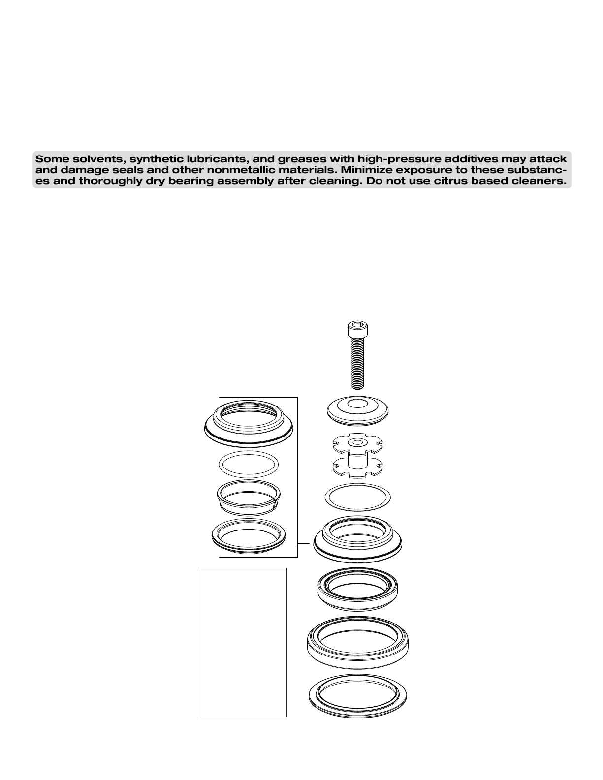
GripLock™ Assembly
The GripLock™ is shipped pre-assembled. If it has been disassembled, then assemble together as shown
in Figure 1. Follow the procedure below.
1. Place thin bearing ring O-ring into outer groove of bearing ring.
2. Place split ring into bearing ring.
3. Snap the bearing ring and split ring into the GripLock™ cap.
4. Feed cap O-ring into the groove created by the assembled parts.
GripLock™ Installation, Final Assembly and Adjustment
1. Remove all sharp edges from inside and outside edges of the cut steerer tube with a le or sand-
paper to avoid shearing the cap O-ring during installation.
2. Apply thin layer of grease onto cap O-ring.
3. Insert fork into frame.
4. Place assembled GripLock™ onto steerer tube. In most cases, the assembly will easily slide onto
steerer. If cap O-ring hangs up on the top edge of the steerer tube, take care not to shear the O-ring.
Gently push the cap O-ring to the side and push the GripLock™ assembly onto the steerer using
steady downward pressure and a slight twisting or rocking motion.
*If you have a carbon steerer tube with expansion plug, loosen the plug prior to bearing
cap installation.
5. Note: If GripLock™ assembly comes apart during installation, go back to “GripLock™ Assembly”
section and then repeat the installation steps.
6. Slide scuff washer, then any spacers and stem on to steerer tube. Thread stem cap screw through
stem cap and into star nut. Tighten to 1.92nm (17 in.lbs.) of torque using 5mm hex wrench. Rotating
the fork in alternating directions while tightening the stem cap will help to optimally seat the bearings.
7. Adjust alignment of stem and then secure stem according to the manufacturer’s specications.
8. Check headset for proper adjustment. When properly adjusted, the fork will rotate smoothly without
play or restriction. Some settling may occur after a few rides; re-adjust as necessary.
New seals will produce some resistance in rotation for the rst 50-100 hours of use. Avoid confusing this
with rubbing or binding that may result from improper installation, poorly cut spacers, or stems that are
not properly faced. We recommend using Chris King Spacers.
Note: It is important to use the King bearing cap and GripLock™ assembly supplied with
the DropSet™ bearings.
Maintenance
Chris King bearings are engineered to provide high performance over a long lifespan – improving over
time. As such, our headsets are designed to be fully serviceable. Occasional adjustment, cleaning, and
re-greasing are all that is required to maintain optimal performance. Riding conditions will dictate how
often service is needed. In wet conditions service may be necessary as often as every 6 months; in dry
conditions, up to every 5 years
To service the headset optimally the bearings will need to be removed from the frame.
GripLock™ Removal
1. Remove stem cap, stem and spacers from steerer tube. Release GripLock™ “lock” by tapping
side of steerer tube with palm of hand or rubber mallet. Do not hit steerer tube from top, as this may
damage the headset bearings.
Servicing the Bearings (Picture tutorial available at chrisking.com)
1. Remove the bearings from the frame.
*Do not attempt to remove the inner, white seal of the headset bearing. This may result
in damage of the seal.
2. Carefully, using a small screwdriver, pick, or penknife, remove the snap ring by gently prying 1.5cm
clockwise from the split in the snap ring. Follow the ring around with the tool until the snap ring is
completely dislodged.
3. Lift and remove exposed rubber seal to access the interior of the bearing.
4. Thoroughly ush the bearing with a light spray lubricant (e.g., WD-40TM) and blow dry.
5. Wipe dirt and other contaminants from the seals and snap rings. Used snap rings and seals can
be reinstalled unless warped, punctured, or otherwise damaged.
Replacement seals and snap rings are available from any authorized Chris King dealers or directly from
Chris King Precision Components.
Some solvents, synthetic lubricants, and greases with high-pressure additives may attack
and damage seals and other nonmetallic materials. Minimize exposure to these substanc-
es and thoroughly dry bearing assembly after cleaning. Do not use citrus based cleaners.
6. Lay a bead of waterproof, synthetic grease around the top of the bearing. Rotate the inner race
to work grease throughout the ball area.
7. Reinstall rubber seal between inner and outer bearing race. Be sure to reinstall seals and snap
ring in their original orientation.
8. Insert the acute edge of snap ring into groove of outer bearing race. Press along entire groove
until snap ring is fully seated; a small gap should be visible between both ends of the snap ring.
9. Turn inner race of bearing by hand to test for binding. If bearings do not run smooth, repeat steps
1-8. Binding is often a result of improperly seated seals and or split rings.
FIGURE 1.
A
B
C
D
E
K
L
M
F
G
H
I
J
A.
B.
C.
D.
E.
F.
G.
H.
I.
J.
K.
L.
M.
stem cap screw
stem cap
star nut
scuff washer
GripLock assembly
GripLock cap
cap O-ring
split ring
bearing ring
bearing ring O-ring
upper bearing
lower bearing
baseplate
Table of contents
Other Chris King Bicycle Accessories manuals


