Christie BC-RAD BL SELECT Series User manual

DIGITAL BRUSHLESS BATTERY TORQUE WRENCH
(BC-RAD BL SELECT INC 900VERSION)
USER GUIDE
W.CHRISTIE (INDUSTRIAL) LTD
CHRISTIE HOUSE, MEADOWBANK ROAD, ROTHERHAM, SOUTH YORKSHIRE, S61 2NF, UK
T: +44(0)1709 550088 F: +44(0)1709 550030 E: INFO:WCHRISTIE.COM W: WWW.WCHRISTIE.COM
Ref: WCOI.112 Date: Feb 19 Issue: 2

Contents
Page Description
- Issue
Introduction
1 Important Safety Notice
BC-RAD Brushless Select System Safety
2 BC-RAD Brushless Select LI-ION Battery Pack Safety
3-4 1.0 –General Information
1.1 –System Components
1.2 - Specifications
4-7 2.0 –Tool System
2.1 –Tool Handle
2.2 –LED Display Interface
2.3 –BC-RAD Brushless Select Li-Ion Battery Pack
2.4 –BC-RAD Brushless Select Battery Charger
8-10 3.0 –LED Display Operation
3.1 –Overview of Interface and Settings
3.2 –Unlock Levels
10 4.0 –Calibration
11-14 5.0 –General Operating Instructions
5.1 –Reaction Arm
5.2 –Torque Operation
14 6.0 –Troubleshooting
15 E.C. Declaration of Conformity
-- Calibration Certificate
16 7.0 –Contact Us
ISSUE
Description
Issue
Date
Initials
First Issue
1
Nov 2018
RA
Second Issue
2
Feb 2019
RA
INTRODUCTION
The BC-RAD Brushless Select Battery Torque Wrench is a handheld, battery driven reversible non-
impacting torque delivery power tool intended to tighten and un-tighten nuts, bolts and threaded fasteners.
The BC-RAD Brushless Select Electrical torque wrench must always be used with the following:-
•Battery Pack Supplied
•Impact Quality Sockets
•Ring and pin fastener system (or similar)
•Reaction Arm
•240V or 110V electrical battery charger (dependant on model purchased)
If the intended use is other than for nuts, bolts and threaded fasteners contact W. Christie (Industrial) LTD
for guidance.
It is the responsibility of the user to consider associated site risks before introducing the equipment into
the work-place.

1
IMPORTANT SAFETY NOTICE
READ ALL SAFETY WARNINGS AND ALL INSTRUCTIONS. FAILURE TO FOLLOW THE
WARNINGS AND INSTRUCTIONS MAY RESULT IN ELECTRIC SHOCK, FIRE, AND/OR
SERIOUS INJURY.
BC-RAD BRUSHLESS SELECT TOOLS ARE SAFE AND RELIABLE. NOT FOLLOWING
PRECAUTIONS AND INSTRUCTIONS OUTLINED HERE CAN RESULT IN DAMAGE TO THE
TOOL, AND INJURY TO THE OPERATOR AND FELLOW WORKERS.
W. CHRISTIE (INDUSTRIAL) LTD IS NOT RESPONSIBLE FOR ANY SUCH INJURY.
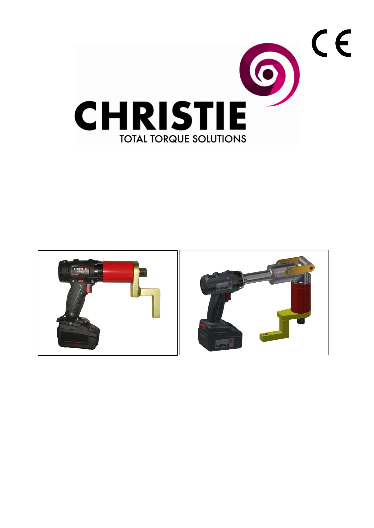
BC-RAD BRUSHLESS SELECT SYSTEM SAFETY
The intended use of the BC-RAD Brushless Select Tool System is for commercial and industrial bolting
applications.
Do not operate the BC-RAD Brushless Select Tool System before reading and understanding this user
manual and noting the Safety Notices displayed on the BC-RAD Brushless Select Tool System and
throughout this manual.
Only qualified personnel with training in the safe operation of torque tooling and the BC-RAD Brushless
Select Tool System should attempt the installation, operation and diagnosis of the BC-RAD Brushless
Select Tool System.
The BC-RAD Brushless Select Tool System is connected to high voltage power and consists of external
rotating parts. Improper training and use can cause serious or fatal injury.
Do not disassemble or attempt to repair the BC-RAD Brushless Select Tool System; doing so will void
warranty. If breakdown, malfunction or damage occurs and the BC-RAD Brushless Select Tool System
fails to operate correctly, contact W. Christie (Industrial) LTD Technical Support (refer to Section 7.0 –
Contact Us).
The BC-RAD Brushless Select Tool System should only be used if environmental storage and operation
specifications have been met. Refer to Section 1.2.3 –Environmental Specifications.
Do not operate the BC-RAD Brushless Select Tool System in explosive atmospheres, including, but not
limited to, the presence of flammable liquids, gases or dust. The BC-RAD Brushless Select Tool System
creates sparks which could ignite these substances.
Do not expose the BC-RAD Brushless Select Tool System to wet conditions. Water in the BC-RAD
Brushless Select Tool System will cause damage to the tool and increase the risk of electric shock.
After long durations of use, the BC-RAD Brushless Select Tool System will become hot. It is
recommended to use the tool in short intervals and allow for cooling between uses to prevent injury to the
operator or damage to the BC-RAD Brushless Select Tool System.
While operating the BC-RAD Brushless Select Tool System, always wear safety goggles and keep all
body parts clear of moving parts and the reaction arm contact point.
Never exceed the Maximum Torque of the BC-RAD Brushless Select Tool System. Failure to comply
will result in void warranty.
The BC-RAD Brushless Select Tool System has been calibrated by a qualified Calibration Technician;
calibration must be done by a qualified Calibration Technician. Improper calibration can cause damage to
the tool and joint.

2
BC-RAD BRUSHLESS SELECT LI-ION BATTERY PACK SAFETY
Only use the BC-RAD Brushless Select Li-Ion Battery Pack with the B-RAD Brushless Select Tool
System. The use of other batteries with the BC-RAD Brushless Select Tool System will cause damage to
the tool.
The BC-RAD Brushless Select Li-Ion Battery Pack should only be charged on the BC-RAD Brushless
Select Battery Charger. If an incompatible charger is used, damage to the BC-RAD Brushless Select
Battery will occur.
Keep the BC-RAD Brushless Select Li-Ion Battery Pack away from any metal objects. If the battery
terminals are connected by a metal object, the battery will short and will cause damage to the battery and
injury to the operator.
Do not expose the BC-RAD Brushless Select Li-Ion Battery Pack to wet conditions. This will cause
damage to the BC-RAD Brushless Select Battery and increase the risk of electric shock.
Do not use faulty or deformed BC-RAD Brushless Select Batteries. Do not attempt to open the BC-RAD
Brushless Select Battery. Do not short circuit the BC-RAD Brushless Select Battery. Failure to comply
will cause damage to the BC-RAD Brushless Select Battery and injury to the operator.
If liquid is ejected from the BC-RAD Brushless Select Battery, avoid contact. If contact with skin occurs,
immediately flush with water. If contact with eyes occurs, immediately flush with water and seek medical
aid. Liquid from the BC-RAD Brushless Select Battery may cause irritation and/or burns.
BC-RAD Brushless Select Li-Ion Battery Packs cannot be disposed of with regular waste. Return BC-
RAD Brushless Select Batteries to W. Christie (Industrial) LTD.
# Ensure battery is changed when the charge level reaches 2 bars. Using the tool at 2 or less bars of
battery power will affect calibration figures #

3
1.0 –GENERAL INFORMATION
1.1 –System Components
The BC-RAD Brushless Select Tool System is supplied with the following parts:
•BC-RAD Brushless Select Tool (Figure 1.1-1)
•Two BC-RAD Brushless Select Li-Ion Battery Packs (Figure 1.1-2)
•BC-RAD Brushless Select Battery Charger (Figure 1.1-3)
•Standard Reaction Arm and Snap Ring (Figure 1.1-4)
•Calibration Certificate
•User Manual
Figure 1.1-1: BC-RAD Brushless Select Figure 1.1-2: BC-RAD Brushless Select Li-Ion Battery Pack
Figure 1.1-3: BC-RAD Brushless Select Battery Charger Figure 1.1-4: Standard Reaction Arm
1.2 –Specifications
1.2.1 –Torque Ranges
The following table outlines the torque ranges, in Newton-Meters, of each BC-RAD Brushless Select
Tool System:
Model
Weight
(Kg)
Max Speed
(RPM)
Torque Range (Nm)
Square
Drive
Minimum
Maximum
BC-RAD 7 BL Select
3.3
21
170
700
3/4"
BC-RAD 14 BL Select
3.5
10
300
1400
3/4"
BC-RAD 14 900BL Select
4.5
71
300
1400
3/4"
BC-RAD 14A BL Select
4.5
71
300
1400
3/4"
BC-RAD 20 BL Select
4.25
5.5
400
2000
1”
BC-RAD 20A BL Select
4.9
19.5
400
2000
1”
BC-RAD 40 BL Select
6.0
2.5
800
4000
1”
BC-RAD 40A BL Select
6.7
20
800
4000
1”
BC-RAD 70 BL Select
8.8
2
1,350
7,000
1-1/2”

4
1.2.2 –Battery Specifications
Ensure that all Battery Specifications are followed when utilising the BC-RAD Brushless Select Tool
System.
Battery Output
Voltage
18 VDC
Current
30 A
Charge Time
60 minutes
Charger Voltage
Input
115 VAC
Output
12 –18 VDC
Charger Output Current
2.5 A
Table 1.2.2: Battery Specifications
1.2.3 –Environmental Specifications
CAUTION Only operate the BC-RAD Brushless Select Tool System if the following environmental
storage and operation specifications have been met.
Temperature Ranges
C
F
Operating Temperature
0 –35
32 –95
Charging Temperature
0 –50
32 –122
Storage Temperature
-25 –70
-13 –158
Humidity
10% to 90% non-condensing
Shock
10G according to DIN IEC 68-2-6/29
Vibration
1G, 10-150Hz according to DIN IEC 68-2-6/29
Required Operating
Conditions
-Non explosive atmosphere
-Dry location
Table 1.2.3: Environmental Specifications
1.2.4 –Cycle of Operation
A Cycle of Operation or a Tool Cycle as used in this manual is defined as:
•5 seconds forward
•10 seconds rest and switch to reverse mode
•5 seconds reverse mode
•20 seconds rest and switch to forward mode
Note: An actual Torque Cycle may vary from the general definition above.
2.0 –TOOL SYSTEM
The following sections give a visual and functional description of the Tool Handle, LED Display
Interface, BC-RAD Brushless Select Li-Ion Battery Pack and BC-RAD Brushless Select Battery Charger.
2.1 Tool Handle
The BC-RAD Brushless Select (Figure 2.1-1) is activated with a Trigger Switch. The Forward/Reverse
Switch controls the direction of rotation. Torque values and tool information are displayed on the 4-digit
LED display. Two buttons are used to enter the desired torque setting. The BC-RAD Brushless Select Li-
Ion Battery Pack is attached to the bottom of the Tool Handle.

5
1. Trigger Switch –tool activation.
2. Forward/Reverse Switch –controls direction
of rotation.
3. LED Display and Up/Down Button Module.
4. BC-RAD Brushless Select Li-Ion Battery
Pack –refer to Section 2.3 –BC-RAD
Brushless Select Li-Ion Battery Pack.
5. Battery Release Button –refer to Section
2.3.1 –Insert/Remove the BC-RAD
Brushless Select Li-Ion Battery Pack.
Figure 2.1-1: BC-RAD Brushless Select and LED Display
2.1.1 –Trigger Lock
The Trigger Lock is useful while transporting or storing the BC-RAD Brushless Select. The Trigger Lock
disables the use of the On/Off Trigger, therefore disabling the tool. It is suggested that while the BC-RAD
Brushless Select is not in use, the Trigger Lock should be enabled.
To enable the Trigger Lock:
•Slide the Forward/Reverse Switch to the Centre Position (neither fully to the right nor fully to the
left).
Note: The On/Off Trigger cannot be depressed.
To disable the Trigger Lock:
•Slide the Forward/Reverse Switch to the Forward Position or the Reverse Position.
Note: The On/Off Trigger can be depressed.
2.2 –LED Display Interface
The LED Display and Up/Down Button
Interface is the user control module for the
BC-RAD Brushless Select Tool System (See
Figure 2.2-1). The LED Display has 4
numeric digits, used to display torque values in
Torque Select mode and the calibration menus
in Calibration mode. The 2 Up/Down
navigation buttons are used to increment and
decrement numeric values, as well as enter and
navigate the various menu systems in the
module. The LED Display will light a small
indicator LED near each button to confirm that
a button is being pushed or held down.
Figure 2.2-1: LED Display
1
2
3
5
4
Up Button
LED Display
Down
Button

6
2.3 –BC-RAD Brushless Select Li-Ion Battery Pack
CAUTION Only use the BC-RAD Brushless Select Li-Ion Battery Pack with the BC-RAD Brushless
Select Tool System. Using third-party batteries may damage the BC-RAD Brushless Select
Tool System.
CAUTION Keep the BC-RAD Brushless Select Li-Ion Battery Pack away from any metal objects. If
the battery terminals are connected by a metal object, the battery will short and cause
damage to the battery and injury to the operator.
The BC-RAD Brushless Select Li-Ion Battery Pack supplies power to the tool; for the BC-RAD
Brushless Select to perform best, ensure the BC-RAD Brushless Select Battery is fully charged and in
good condition before use. In optimal conditions, the BC-RAD Brushless Select Battery should be
capable of approximately 100 Torque Cycles at 50% of the Maximum Torque on a joint with a hardness
of approximately 10 degrees.
Note: The application torque, joint hardness, battery condition, age and operating temperature will affect
the actual number of Torque Cycles per charge.
2.3.1 –Insert / Remove the BC-RAD Brushless Select Li-Ion Battery Pack
To insert the BC-RAD Brushless Select Battery:
1. Ensure the On/Off Trigger is in the Off Position (not depressed).
2. Align the BC-RAD Brushless Select Battery with the bottom of the Tool Handle.
3. Slide the BC-RAD Brushless Select Battery into place until it is fully seated.
Note: A click will confirm that the BC-RAD Brushless Select Battery is locked in place.
4. Check that the BC-RAD Brushless Select Battery is locked in place by trying to slide it out of
place.
To remove the BC-RAD Brushless Select Battery:
1. Press and hold the Battery Release Button.
2. Slide the BC-RAD Brushless Select Battery away from the Tool Handle.
2.3.2 - Check BC-RAD Brushless Select Battery Charge
To check the BC-RAD Brushless Select Battery Charge:
1. Press the “Charge” button on the BC-RAD Brushless Select Battery (Figure 2.3.2-1).
Result: The Red or Green Bars will light up. If all the Bars are illuminated, the Battery is
fully charged. If none of the Bars are illuminated, the BC-RAD Brushless Select Battery is
completely discharged and needs charging (refer to Section 2.4.1 –Charging the BC-RAD
Brushless Select Li-Ion Battery Pack).
Figure 2.3.2-1: BC-RAD Brushless Select Li-Ion Battery Pack
Charge Button

7
2.4 BC-RAD Brushless Select Battery Charger
CAUTION The BC-RAD Brushless Select Li-Ion Battery Pack should only be charged on the BC-RAD
Brushless Select Battery Charger. If an incompatible charger is used, damage to the BC-
RAD Brushless Select Battery will occur.
The Charging Status Display (Figure 2.4-1) on the BC-RAD Brushless Select Battery
Charger is used to notify the operator when the BC-RAD Brushless Select Battery is
charging, when the charge is complete and if there is an error.
Figure 2.4-1: Charging Status Display
2.4.1 Charging the BC-RAD Brushless Select Li-Ion Battery Pack
Note: The temperature range for charging is 0˚C to 50˚C (32 F to 122 F).
To charge the BC-RAD Brushless Select Battery:
1. Plug the BC-RAD Brushless Select Battery Charger into the wall outlet.
Result: The Red Warning Light will turn on for one second and then the Green Status Light
will turn on for one second.
2. Align the BC-RAD Brushless Select Battery with the BC-RAD Brushless Select Battery Charger.
3. Slide the BC-RAD Brushless Select Battery into place.
Result: The Green Status Light will flash while the BC-RAD Brushless Select Battery is
charging.
When the BC-RAD Brushless Select Battery has been fully charged, the Green Status Light will stop
flashing and stay illuminated. Until the BC-RAD Brushless Select Battery is removed from the BC-RAD
Brushless Select Charger, the Charger will switch to conservation mode which will maintain the battery
charge at maximum capacity.
To remove the BC-RAD Brushless Select Battery:
1. Slide the BC-RAD Brushless Select Battery away from the BC-RAD Brushless Select Charger.
2. Check that the BC-RAD Brushless Select Battery is fully charged (refer to Section 2.3.2 –Check
BC-RAD Brushless Select Battery Charge).
2.4.2 –Charging Errors
The Red Warning Light is on:
The BC-RAD Brushless Select Battery is not charging because its temperature is not within the required
temperature range for charging. When the BC-RAD Brushless Select Battery’s temperature moves within
the required range for charging, the Red Warning Light will turn off and charging will commence.
The Red Warning Light is flashing:
The BC-RAD Brushless Select Battery may be placed incorrectly on the BC-RAD Brushless Select
Battery Charger. Remove the BC-RAD Brushless Select Battery and replace it correctly on the BC-RAD
Brushless Select Battery Charger. If the Red Warning Light continues to flash, the BC-RAD Brushless
Select Battery is defective; remove the BC-RAD Brushless Select Battery immediately. If these problems
continue, contact W. Christie (Industrial) LTD. Technical Support (refer to Section 7.0 –Contact Us)
Green Status Light
Red Warning Light

8
3.0 LED DISPLAY OPERATION
3.1 Overview of Interface and Settings
3.1.1. Changing Torque
When the B-RAD Brushless Select is powered on, the LED Display will start in Torque Select Mode.
The torque units are indicated by the LED dots on the two-button keypad, which change depending on the
value shown on the LED display (refer to Section 3.1.3 –To Change the Torque Units).
The torque may be set in levels from 1 to 50 instead of using torque units. See Section 3 –Unlock Levels
and refer to “Table Mode.”
To change the torque value:
1. Press and hold a button until a digit starts blinking. Pressing the button starts the left-most
digit blinking. If you press and hold the button again, the selected digit moves to the right.
The opposite happens with the button.
2. Press the or button to change the torque value as desired.
3. The selected torque value will be saved after 5 seconds, and then the tool is ready to run.
3.1.2. Information Menu
The Information Menu allows you to change torque units, view the battery voltage, change LED
brightness, enter an unlock code, and view the program version. The menu items are described below.
To enter the Information Menu:
•While in Torque Select mode, hold the button and momentarily press the button.
•To move to the next item, hold the button and press the button. To go to a previous menu
option, hold the button and press the button.
•To exit the menu, hold both buttons until the display flashes and the Torque Value is displayed.
3.1.3 To change the torque units:
•Press the or button to toggle between “F” (Foot-pounds) and “n” (Newton-metres) as shown
in Figures 3.1-1 and 3.1-2 below.
Figure 3.1-1: Units –ft·lb
Figure 3.1-2: Units –N·m
•To exit the Unit Select menu, press and hold both buttons.
NOTICE:
This manual applies to the following firmware release:
V6-10-13
Use with any other firmware version may produce unexpected results.

9
•The N·m indicator lights when N·m units are used (Figure 3.1-3), and the ft·lb indicator lights
when ft·lb units are used (Figure 3.1-4).
Figure 3.1-3: N·m Display
Figure 3.1-4: ft·lb Display
Note: When the units are changed, the torque setting is converted to the nearest torque setting in the new units.
3.1.4 To view the battery voltage:
•Advance to the next menu item after Unit Select. The display will read “batt” and display the
battery voltage.
•When the battery voltage gets too low, the display flashes “batt” to warn you that the battery needs
charging.
3.1.5 To change the LED brightness:
•Move to the next menu item. The display will read “Lite,” then a graph will be shown depicting
the LED brightness level. Use the and buttons to change the LED brightness.
3..1.6 To enter a Lock or Unlock code:
1. Move to the next menu item, labelled “Lock.” The line indicator on the right side of the screen
will keep track of the number of button presses used to enter a code.
2. Enter a code using the and buttons. The desired code will depend on which features are
needed. See Section 3.2 –Unlock Levels for more information.
3. Press and hold both buttons to enter the code and return to Torque Mode.
3.1.7 To view Program version:
•Move to the last menu item, labelled “Prog.” The program version number will scroll across the
screen.

10
3.2 Unlock Levels
The B-RAD Brushless Select has several access levels that change the operation of the tool and the
interface. The table below describes the Locked and Unlock levels.
Access Level
Description
Code
Locked/Basic
Locked mode freezes the output torque value. Basic menu options
are available as below.
Basic mode enables selecting torque values and switching between
Torque and Table modes.
Information Menu: Unit Select, Battery level, LED brightness,
Code entry, and Program version.
Tool Menu: displays model, serial number, and torque minimum
and maximum.
Calibrate
Change calibration values.
Locked
Table Mode
Change from Torque Mode to Table Mode. Choose from 50 torque
levels over the calibrated range. The tool is in Basic.
Torque Mode
Change from Table Mode to Torque Mode. Display torque in
physical units (ft·lb or N·m) as calibrated. This is the default
setting.
Note: Only available while in Table Mode.
4.0 –CALIBRATION
Calibration should only be carried out by W. Christie (Industrial) LTD.

11
5.0 –GENERAL OPERATING INSTRUCTIONS
WARNING Only qualified personnel with training in the safe operation of torque tooling and the BC-
RAD Brushless Select Tool System should operate this tool. Refer to the Important Safety
Notice for more information.
The BC-RAD Brushless Select operates in Torque Cycles. The Torque Cycle passes when the Actual
Torque reaches the Target Torque, and the Cycle fails if it is interrupted before the Actual Torque reaches
the Target Torque.
This section instructs the operator in the use of the Reaction Arm needed for BC-RAD Brushless Select
operation and how to conduct a Torque Cycle.
5.1 –Reaction Arm
WARNING Always keep body parts clear of the Reaction Arm when the BC-RAD Brushless Select
Tool System is in use. Serious injury could occur.
CAUTION Ensure the Reaction Arm has a solid contact point before operating the BC-RAD Brushless
Select Tool System.
5.1.1 –Installing the Reaction Arm
Ensure the Reaction Arm and Snap Ring are installed securely to hold the Reaction Arm in place. Make
sure the Reaction Arm is in contact with a solid Reaction Point before you operate the tool. Keep your
body parts clear of the Reaction Arm when the tool is in operation.
When the tool is in operation the Reaction Arm rotates in the opposite direction to the Output Square
Drive and must be allowed to rest squarely against a solid object or surface adjacent to the bolt to be
tightened (Figure 5.1.1-1).
Figure 5.1.1-1 –Reaction Arm Rotation
Reaction
Reaction
Socket
Socket
Reaction
Reaction
TRAPPING HAZARD:-
Always keep hands, fingers and body parts clear of the reaction arm when the tool is in use or trapping injury will result
Clockwise Operation
Counter Clockwise Operation

12
CAUTION Keep your hand and body parts clear of the Reaction Arm and barrel when the tool is in
operation.
5.1.2 –Reaction Arm Height
Ensure the height of the socket is even with the height of the Reaction Arm as seen below in Figure 5.1.2-
1. The height of the socket cannot be shorter or higher than the height of the Reaction Arm as seen below
in Figure 5.1.2-2.
CORRECT: The Reaction Arm and socket are even height
Figure 5.1.2-1: Correct Height
INCORRECT: The leg of the Reaction Arm is too short on the left side, and too long on the right side.
Figure 5.1.2-2: Incorrect Height
IMPROPER REACTION WILL VOID WARRANTY AND CAN CAUSE PREMATURE TOOL
FAILURE.
5.1.3 –Reaction Arm Foot
Ensure the foot of the Reaction Arm aligns with the
length of the nut as seen in Figure 5.1.3-1. The length
of the foot cannot be shorter or longer than the nut as
seen in Figure 5.1.3-2.
CORRECT: The foot of the Reaction Arm aligns
with the length of the nut.
Figure 5.1.3-1: Correct Length

13
INCORRECT: The foot of the Reaction Arm is too short on the left side, and too long on the right side.
Figure 5.1.3-2: Incorrect Length
Please contact W. Christie (Industrial) LTD for custom Reaction Arms.
5.1.4 –Reaction Points
Ensure the Reaction Arm reacts off the middle of the foot as seen in Figure 5.1.4-1. Do not react off the
heel of the reaction foot as seen in Figure 5.1.4-2.
CORRECT: Reaction Arm is reacting off the middle of the Reaction Arm’s foot.
Figure 5.1.4-1: Correct Reaction Point
INCORRECT: Reaction Arm is reacting off the heel of the Reaction Arm. This can cause premature
tool failure.
Figure 5.1.4-2: Incorrect Reaction Point

14
5.2 Torque Operation
To operate the tool in a Torque Cycle:
1. Ensure the tool is in Torque Select mode (Figure 5.2-1. Also see Section 3.1).
Figure 5.2-1: Torque Select Mode
2. Ensure the LED Display is showing the correct units (see Section 3.1.3 –Unit Select Menu).
3. Increment or decrement the displayed torque until the desired torque is displayed.
Note: The Display will increment or decrement by 10 units with a single button push, or by 100 units if a
button is held down. See Section 3.1.1 –Changing Torque for more information.
4. The BC-RAD Select Tool System will immediately be ready to torque at the displayed setting.
Place the BC-RAD Select on the joint system.
5. Ensure the Forward/Reverse Switch is in the Forward position.
6. Press and hold the On/Off Trigger.
Note: To stop the Torque Cycle at any time, release the On/Off Trigger.
7. When the BC-RAD Select reaches the selected Torque, the tool will stop turning. Release the
On/Off Trigger.
6.0 - TROUBLESHOOTING
IMPORTANT Disassembling or attempting repair will void warranty.
If breakdown, malfunction, or error occurs, contact W. Christie (Industrial) LTD Support (refer to Section
7.0 –Contact Us).
The LED Display may exhibit abnormal behaviour depending on operating conditions, frequency of use,
or excessive wear on the Display Module.
The Display Module is designed to withstand normal use over the lifetime of the BC-RAD Brushless
Select Tool System; however, as a sensitive electronic device it is susceptible to damage caused by shock,
moisture, or excessive force.

15
E.C. DECLARATION OF CONFORMITY
MODELS COVERED: BC-RAD 7 BL Select, BC-RAD 14 BL Select
BC-RAD 14A BL Select, BC-RAD 20 BL Select
BC-RAD 20A BL Select, BC-RAD 40 BL Select
BC-RAD 40A BL Select, BC-RAD 70 BL Select
DESCRIPTION: Digital Battery Torque Wrench
We hereby declare that the following machinery complies with the essential health and safety
requirements of the European Machinery Directive 2006/42/EC published on the 9th June 2006
W Christie (Industrial) Ltd, Meadowbank Road, Rotherham S61 2NF, United Kingdom.
This machinery has been designed and manufactured in accordance with the following transposed
harmonised European Standard:-
BS EN ISO 12100-2:2003 Safety of Machinery –Technical Principles
BS EN 60745-1:2006 Hand-held Motor Operated Electric Tools –Safety –General Requirements
SIGNED: POSITION: Senior Applications Engineer
NAME: R. G. Askham
On behalf of W Christie (Industrial) Ltd

16
10.0 CONTACT US
This manual suits for next models
9
Table of contents
Other Christie Power Tools manuals