manuals.online logo
Brands
  1. Home
  2. •
  3. Brands
  4. •
  5. Chromalox
  6. •
  7. Electric Heater
  8. •
  9. Chromalox PG407-3 User manual

Chromalox PG407-3 User manual

DIVISION
4
SECTION
RAD
SALES
REFERENCE
DATE
SERVICE REFERENCE
Installation, Operation
and
RENEWAL PARTS IDENTIFICATION
161-048766-001
FEBRUARY, 1987
PG407-3
(Supersedes PG407-2)
Chromalox
®
© 2010 Chromalox, Inc.
Chromalox Type RAD Radiant Heaters
Converting Styles 0, 1, 3 and 3A to 3B
The current Chromalox Style 3B RAD has superseded earlier
Styles 0, 1, 3 and 3A RAD heaters. These instructions are for con-
verting these earlier models to the current Style 3B. This conversion
is necessary because replacement parts for the old models are no
longer available.
The changes involved are primarily in the terminal area as
shown in Figures I, 2 and 3. Match-up one of the Figures with your
heater's terminal arrangement and order the corresponding parts bag
(Figures 4 and 5). If an element or other part listed in Table A (page
3) is necessary, order according to heater housing length and the
voltage and wattage stamped on the element and the heater name-
plate.
For complete installation information for type RAD - Style
3B, request Chromalox Service Reference sheet PG404.
GENERAL
CONVERSION
Figure 1 – Style 0 and 1 Terminal Area Assembly
CAUTION: Hazard of electric shock. Disconnect
power before servicing heater.
A. CONVERTING STYLES 0 AND 1 TO
STYLE 3B RADIANT HEATER
1. Completely disassemble heater. Re-use the heating element (if
desired) and the extruded aluminum housing (Fig. 7). Scrap all
the other parts.
2. Drill #24 (.152" dia.) hole in the back of the extruded housing
, 3" from each end. (See Fig. 7)
3. NOTE: If replacing old element with a new one, omit this step.
Remove wire retaining loops ® (Fig. 6) from the elements and
replace with wire loops fashioned from #15 gage (.072" dia.) or
larger stainless steel wire located 2-1/4” from each end of the
sheath. Other high temperature materials such as nichrome may
be substituted. Braze or tack weld the loops in position.
4. Besides the Parts Bag 168-016585-002 (Fig. 4), you will need
insulation bushings ®, element support clips , reflector ®
and element (if required) as listed in Table A, page 2.
NOTE: Quantities of these parts, as well as size of element and
reflector will be determined by the heater housing length of the old
unit.
5. Assemble heater as shown in Figure 7.
A
B
6
7
2
CONVERSION (cont’d.)
B. CONVERTING STYLE 3 TO STYLE 3B RADIANT HEATER
1. Completely disassemble heater. Re-use the heating element O
(if desired), the extruded aluminum housing. the element sup-
port clips ••• and insulation bushing •• . Scrap all other parts.
2. Drill #24 (.152" dia.) hole in the wiring trough of the extruded
housing •• , 3" from each end.
NOTE: If replacing old element with a new one, omit steps 3 and 4.
3. Remove terminal connector from terminal pin and replace with
terminal connector 302-019961-002. The location of this con-
nector is as shown in Figure 6.
4. Fashion wire loops from #15 gage (.072" dia.) or larger high
temperature wire (such as stainless steel or nichrome) and braze
or tack weld these loops in position 2-1/4” from each sheath end
of the element.
5. Assemble heater as shown in Figure 7 using Parts Bag 168-
016585-002.
C. CONVERTING STYLE 3A TO STYLE 3B RADIANT HEATER
1. Completely disassemble heater. Scrap the bottom terminal
blocks •••, the terminal block support brackets •••, the
Tinnerman®“U” speed nuts •••, the terminal block support
bracket screws ••• and the terminal block screws •••. Re-use all
the other parts, including the heating element unless a new one
is required. In this case order an element from Table A, page 3
with same voltage and wattage and for same heater housing
length as old unit.
2. Assemble heater as shown in Figure 7 using Parts Bag 168-
016585-001.
Aluminum
Housing
1
6
6
7
A
Figure 2 – Style 3 Terminal Area Assembly
Aluminum Housing
12
9
15
17
Figure 3 – Style 3A RAD Heater Terminal Area Assembly
1
7
6
A
9
17
16
15
12
RENEWAL PARTS IDENTIFICATION
13
3
11
12
4
12
9
10 5
14
Figure 4 – Parts Bag 168-016505-002 (to convert Style 0, 1 and 3B
12
11
12
9
10
Figure 5 – Parts Bag 168-016585-001
(to convert Style 3A to Style 3B)
PARTS BAG 168-016585-001 Consists of:
Terminal Block ...........303-016367-001 (2)
Speed Nuts.................272-048153·005 (4)
Terminal Block ...........303-014326-001 (2)
Screws - #8 x 1" Lg. ..248-075519-095 (6)
9
10
11
12
PARTS BAG 168-016585-001 Consists of:
Terminal Cover..............306-014405-001 (2)
Terminal Cover Clip.......056-014401-002 (4)
End Plate.......................220-017278-001 (2)
Terminal Block ..............303-016367-001 (2)
Speed Nuts....................272-048153-005 (4)
Terminal Block ..............303-014326-001 (2)
Screws - #8 x 1” ...........248-075519-095 (6)
Screws - #8 x 3/8” ........248-075519·080 (4)
Screws - #8-32 x 3/8”...248-075512-053 (4)
3
4
5
9
10
11
12
13
14
RENEWAL PARTS IDENTIFICATION
MISCELLANEOUS HARDWARE
Screws
Terminal Screw .....................................................................248-046044-002(2)
#8 x 1” Lg..............................................................................248-075519-095(6)
#8 x 3/8” Lg...........................................................................248-075519-080(4)
#8-32 x 3/8” Lg. ....................................................................248-075512-053(4)
MISCELLANEOUS HARDWARE
Terminal Screw .....................................................................303-016367-001(2)
Speed Nuts ............................................................................272-048153·005(4)
Terminal Block.......................................................................303-014326-001(2)
Saddle Clamp ........................................................................238-026539-001(2)
HEATER MOUNTING CLAMP ASSEMBLY
For mounting heater with catalog numbers up to Cat. No. RAD 7000
use mounting clamp assembly part no. 168-013071-001. For mount-
ing heaters above Cat. No. RAD 7000 use mounting clamp assem-
bly part no. 168-013071-002.
8
12
13
14
8
10
11
15
13
3
8
15
1
9
12
14
5
A
67
Aluminum
Housing
10
4
11
12
Figure 7 – Style 3B RAD Heater Terminal Area Assembly
Heater Element Reflector Insulation Element
Housing Length Volts Watts Catalog Number Sheet Bushing Support Clip
1
2
6
7
120 RTU-2083A-120V
208 RTU-2083AV
24-3/8” 240 800 RTU-2083A-240V 234-013411-001 ________ ________
275 RTU-2083AV-275V
120 RTU-3113A-120V
208 RTU-3113AV
30-5/8” 240 1100 RTU-3113A-240V 234-013411-012 ________ ________
275 RTU-3113AV
208 RTU-4183AV
240 RTU-4183A-240V
46-5/8” 275 1800 RTU-4183AV 234-013411-014 032-013454-001 (2) 059-013424-001
480 RTU-4183A-480
208 RTU-5253AV
240 RTU-5253A-240V
61-3/8” 275 2500 RTU-5253AV 234-013411-016 032-013454-001 (6) 059-013424-001 (3)
480 RTU-5253A-480V
208 RTU-6303AV
240 RTU-6303A-240V
73-3/4” 275 3000 RTU-6303AV 234-013411-018 032-013454-001 (8) 059-013424-001 (4)
480 RTU-6303A-480V
208 RTU-7363AV 234-013411-004*
240 RTU-7363A-240 and
85-3/4” 275 3600 RTU-7363AV 234-013411-012* 032-013454-001 (10) 059-013424-001 (5)
480 RTU-7363A-480V
*For ease of installation. these reflectors shipped in two pieces (one each of part numbers listed).
NOTE: Part numbers suffixed by a number in ( ) Indicates the quantity of the same part number used.
2150 N. RULON WHITE BLVD., OGDEN, UT 84404
Phone: 1-800-368-2493 www.chromalox.com
Limited Warranty:
Please refer to the Chromalox limited warranty applicable to this product at
http://www.chromalox.com/customer-service/policies/termsofsale.aspx.

Other Chromalox Electric Heater manuals

Chromalox PF497-1 User manual

Chromalox

Chromalox PF497-1 User manual

Chromalox PF495-1 User manual

Chromalox

Chromalox PF495-1 User manual

Chromalox TUFF-TUBE PD437-4 Installation instructions

Chromalox

Chromalox TUFF-TUBE PD437-4 Installation instructions

Chromalox PD441-1 Assembly instructions

Chromalox

Chromalox PD441-1 Assembly instructions

Chromalox POO401-9 User manual

Chromalox

Chromalox POO401-9 User manual

Chromalox PD411-10 Assembly instructions

Chromalox

Chromalox PD411-10 Assembly instructions

Chromalox PD412-5 User manual

Chromalox

Chromalox PD412-5 User manual

Chromalox PG421-1 User manual

Chromalox

Chromalox PG421-1 User manual

Chromalox STAR Series User manual

Chromalox

Chromalox STAR Series User manual

Chromalox RST PN400-3 User manual

Chromalox

Chromalox RST PN400-3 User manual

Chromalox PF450-5 User manual

Chromalox

Chromalox PF450-5 User manual

Chromalox NWHO(F)-27 User manual

Chromalox

Chromalox NWHO(F)-27 User manual

Chromalox U-RAD PG405-5 User manual

Chromalox

Chromalox U-RAD PG405-5 User manual

Chromalox PN403-1 User manual

Chromalox

Chromalox PN403-1 User manual

Chromalox PG417-3 User manual

Chromalox

Chromalox PG417-3 User manual

Chromalox PF477-2 Installation and operating instructions

Chromalox

Chromalox PF477-2 Installation and operating instructions

Chromalox PG424-1 User manual

Chromalox

Chromalox PG424-1 User manual

Chromalox STAR PG434-3 User manual

Chromalox

Chromalox STAR PG434-3 User manual

Chromalox PG412-10 User manual

Chromalox

Chromalox PG412-10 User manual

Chromalox NWHO-33015 User manual

Chromalox

Chromalox NWHO-33015 User manual

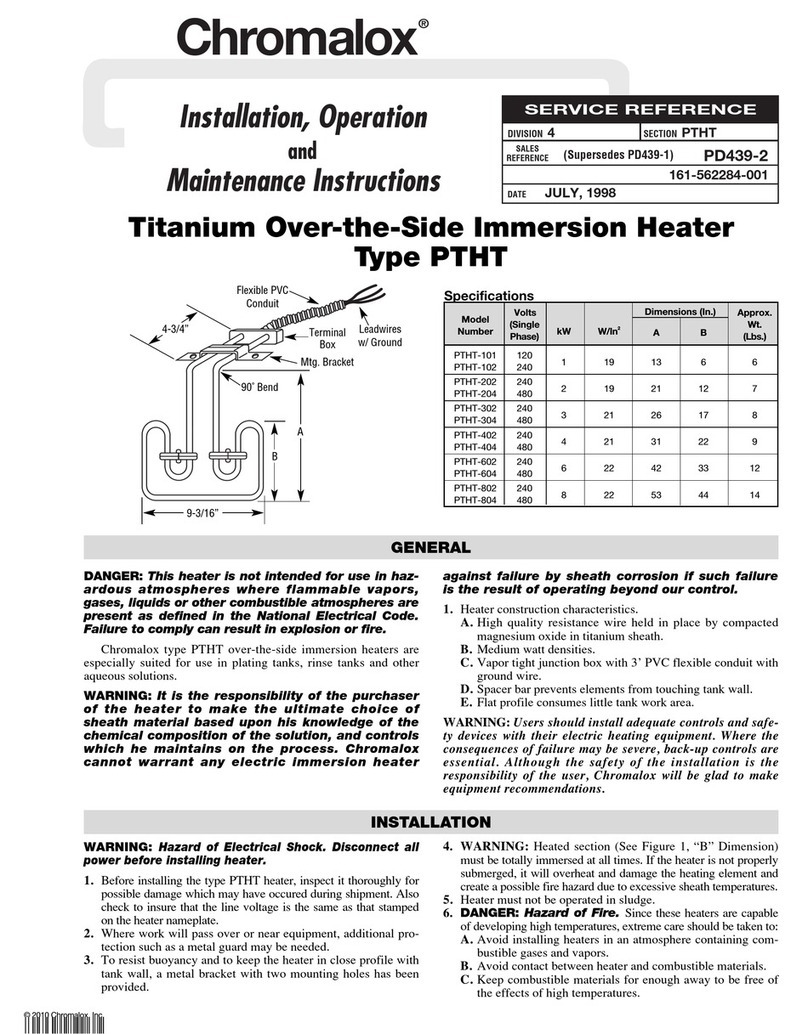
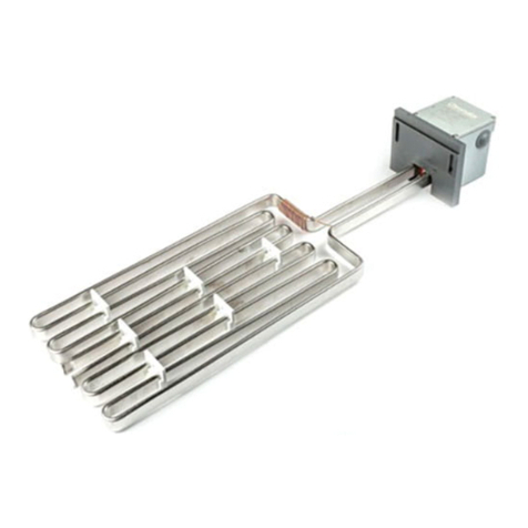
Chromalox PTHT-101 Assembly instructions

Chromalox

Chromalox PTHT-101 Assembly instructions

Chromalox PD438-2 Assembly instructions

Chromalox

Chromalox PD438-2 Assembly instructions

Chromalox PM400-2 User manual

Chromalox

Chromalox PM400-2 User manual

Chromalox SRCCH-1 User manual

Chromalox

Chromalox SRCCH-1 User manual

Popular Electric Heater manuals by other brands

Olsberg 14/534 instruction manual

Olsberg

Olsberg 14/534 instruction manual

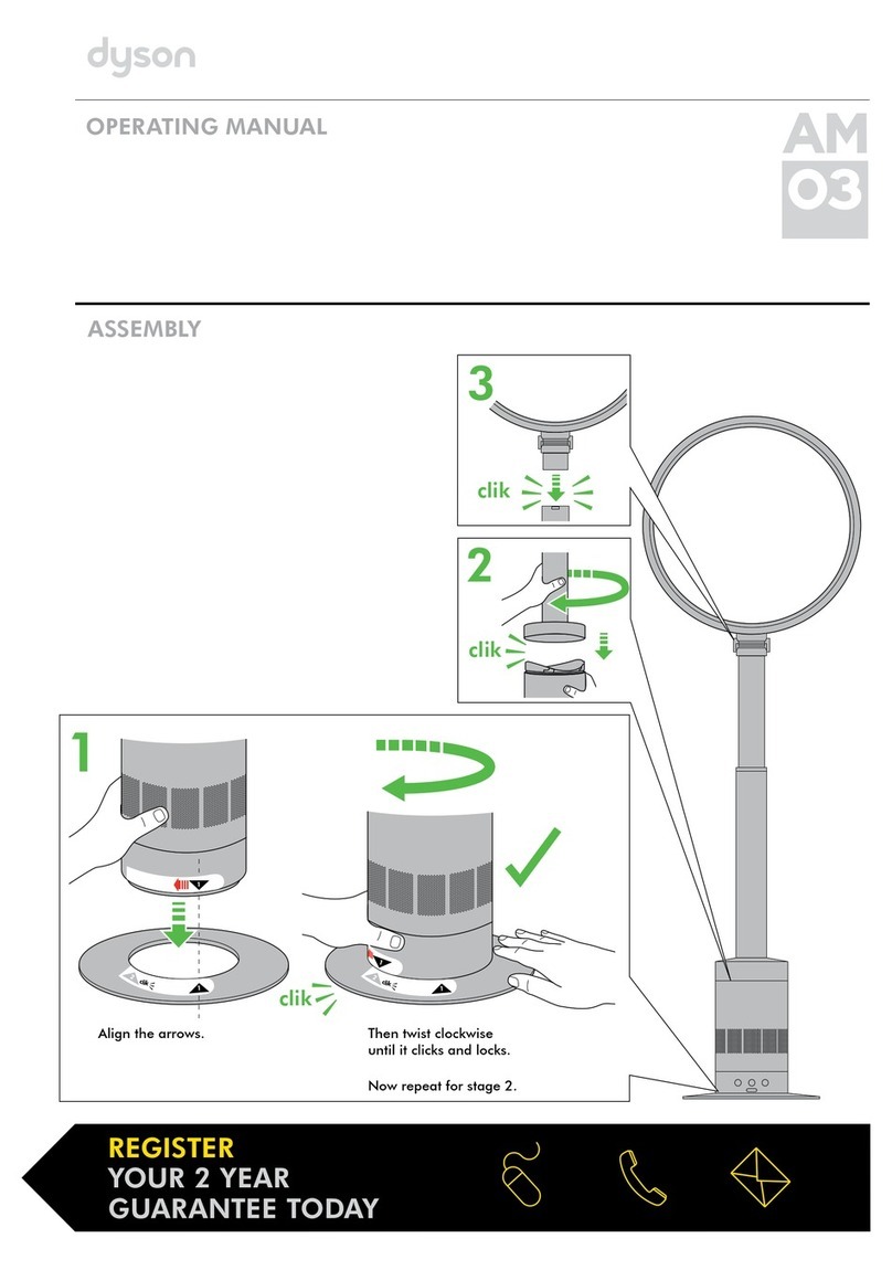
Dyson AM03 operating manual

Dyson

Dyson AM03 operating manual

Valor Fires 850 Installer and owner guide

Valor Fires

Valor Fires 850 Installer and owner guide

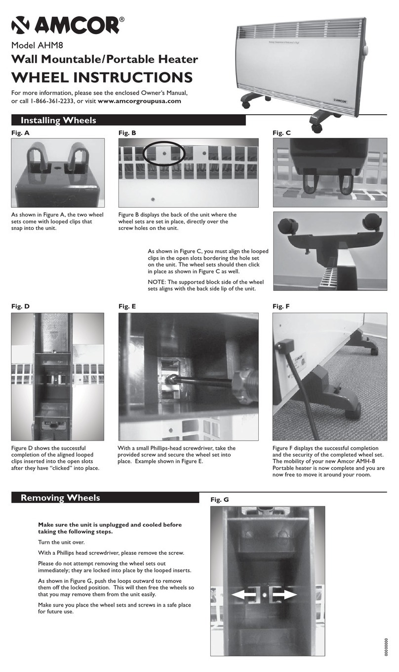
Amcor AHM8 instructions

Amcor

Amcor AHM8 instructions

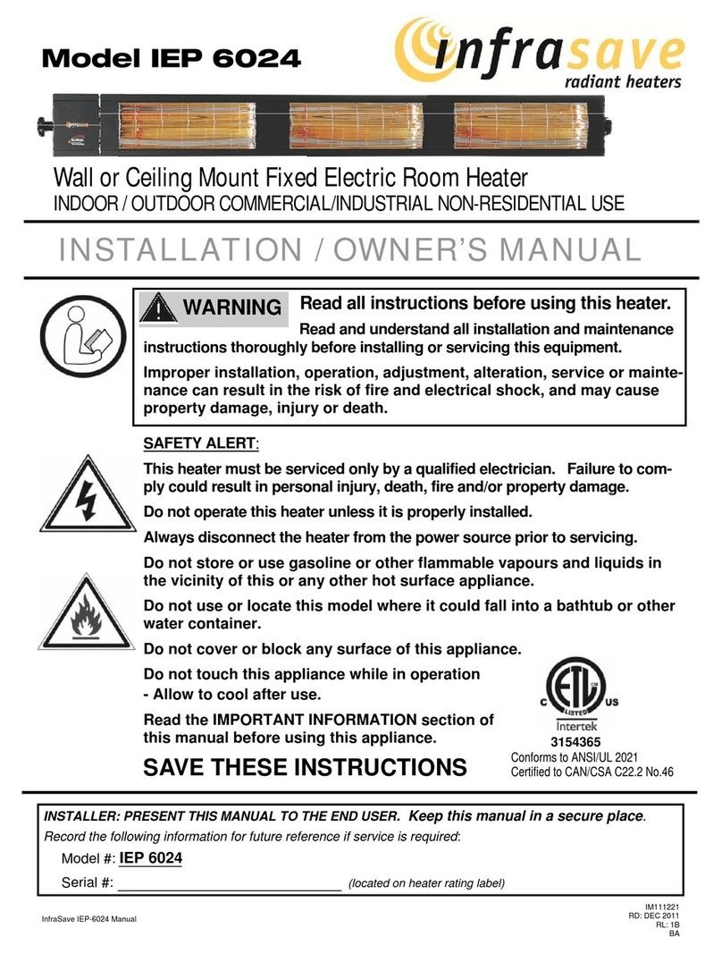
infrasave IEP 6024 Installation & owner's manual

infrasave

infrasave IEP 6024 Installation & owner's manual

KALOS KLEH121-0300 Assembly instructions

KALOS

KALOS KLEH121-0300 Assembly instructions

Reznor EMC Series instructions

Reznor

Reznor EMC Series instructions

Objecto T3 user manual

Objecto

Objecto T3 user manual

Anslut 016481 operating instructions

Anslut

Anslut 016481 operating instructions

Daikin EEH01A6 installation manual

Daikin

Daikin EEH01A6 installation manual

EUROM QH1203 instruction manual

EUROM

EUROM QH1203 instruction manual

DELTACALOR PAPILLON 1 Operation and installation manual

DELTACALOR

DELTACALOR PAPILLON 1 Operation and installation manual

HELLER CWH20NS instruction manual

HELLER

HELLER CWH20NS instruction manual

EUROM Alutherm Baseboard 1000 user manual

EUROM

EUROM Alutherm Baseboard 1000 user manual

Heatscope SMARTBOX Original installation and instruction manual

Heatscope

Heatscope SMARTBOX Original installation and instruction manual

Frico TIG203-0 instructions

Frico

Frico TIG203-0 instructions

NuTone QT9093WH instruction manual

NuTone

NuTone QT9093WH instruction manual

Stanley EH6883 user guide

Stanley

Stanley EH6883 user guide

manuals.online logo
manuals.online logoBrands
  • About & Mission
  • Contact us
  • Privacy Policy
  • Terms and Conditions

Copyright 2025 Manuals.Online. All Rights Reserved.