manuals.online logo
Brands
  1. Home
  2. •
  3. Brands
  4. •
  5. Chromalox
  6. •
  7. Electric Heater
  8. •
  9. Chromalox PG424-1 User manual

Chromalox PG424-1 User manual

(Supersedes PG424-1)
PG424-2
U-RP
161-058090-001
JULY, 2006
4
and
Installation, Operation
RENEWAL PARTS IDENTIFICATION
Type U-RP Radiant Heater
© 2010 Chromalox, Inc.
Specifications – Table A
Dimensions (In.)
BCD
Overall Heated Overall
Model Volts kW A Length Length Height
U-RP-410V 208 or 275 13.2 11-5/8 57-1/2 48 12
U-RP-410 240 or 480 13.2 11-5/8 57-1/2 48 12
U-RP-420V 208 or 275 26.4 23-5/8 57-1/2 48 24
U-RP-420 240 or 480 26.4 23-5/8 57-1/2 48 24
U-RP-510V 208 or 275 18 11-5/8 75-1/2 66 12
U-RP-510 240 or 480 18 11-5/8 75-1/2 66 12
U-RP-520V 208 or 275 36 23-5/8 75-1/2 66 24
U-RP-520 240 or 480 36 23-5/8 75-1/2 66 24
Please familiarize yourself with these instructions before
attempting to install or connect this radiant heater
4-5/8”
11-3/8”
D
8-1/8”
1-5/8”
4-7/8”
4-1/2”
C
B
A
Before installing
1. Open carton and remove heater at the place of installation.
2. Check nameplate volt and watt rating against your power supply
voltage and heating requirements of your installation. This name-
plate is located on one end of the heater.
MOUNTING
1. Framing: Fabricate structural support using angle iron or contin-
uous slot metal framing (manufactured by others). Dimension
framing per Table B and Figure 1 for your size panel.
2. Assembly: Position U-RP radiant panel on fabricated structural
support and attach using 1/2” diameter bolts of suitable length
(see Fig. 2).
3. Insulation: Where unusually high work temperatures are encoun-
tered, it may be desirable to insulate backs of heaters with high
temperature fibrous insulation. A suggested method of accom-
plishing this is indicated in Figure 2.
D
I
H
G
F
Terminal Box Cover
2-5/16”
A
1-1/4” Conduit
Opening 1-5/32” x 9/16” Slot (Typ.) Mtg. Bracket (Typ.)
Figure 1 – Aluminum Extruded Section
Mounting – Table A
Dimensions (In.)
No. of Mounting
Model Brackets F G H I
U-RP-410V 2 44-3/4 — — 8-5/8
U-RP-410
U-RP-420V 2 44-3/4 — — 20-5/8
U-RP-420
U-RP-510V 3 62-3/4 32-1/4 30-1/2 8-5/8
U-RP-510
U-RP-520V 3 62-3/4 32-1/4 30-1/2 20-5/8
U-RP-520
Figure 2 – Typical installation
Insulation
Structural
Support Bolt
Radiant Panel
FIRE/EXPOSION HAZARD. This heater is not
intended for use in hazardous atmospheres where
flammable vapors, gases, liquids or other com-
bustible atmospheres are present as defined in
the National Electrical Code. Failure to comply can
result in personal injury or property damage
.
The system designer is responsible for the safety
of this equipment and should install adequate
back-up controls and safety devices with their
electric heating equipment. Where the conse-
quences of failure could result in personal injury
or property damage, back-up controls are essen-
tial.
CAUTION: For your own safety –
Before energizing this heater:
1. Be sure all electrical connections are tightly made.
2. Be sure that all conductors are properly insulated.
3. Be sure that the terminal cover has been properly replaced.
A. Controlling Radiant Intensity –
Standard Radiant Panels are built to operate at 40 watts per
square inch on the element sheath. When it is desired to reduce
the radiant intensity, one or more of the following methods may
be used.
1. INPUT CONTROLLERS These motor-driven cycling devices
can be used to vary heater output capacity from 4 to 100%. They
are usually connected in holding coil circuit of magnetic contac-
tors. See Chromalox Radiant Heater Manual for further informa-
tion regarding Input Controllers and Contactors.
2. SOLID STATE THYRISTOR POWER CONTROLLERS
For best non-contact control of radiant heat, a Series #6
Chromalox Thyristor Power Controller with manual potentiome-
ter setting is recommended. Truly proportional output from 0-
100% can be easily dialed-in to suit the particular product or
process requirements. The Series #6 panels are pre-engineered,
pre-packaged assemblies in an enclosure with circuit disconnect
provided and ready for installation.
B. Maximum Ambient Temperatures –
CHROMALOX Radiant Panels are not recommended for
applications in ambient temperatures exceeding 450˚F. Higher
ambient temperatures mean shorter heater life.
Maximum work temperature in a given time depends on sev-
eral factors: Reflectivity of work, specific heat of work, mass of
work, kW input and losses from oven and time of exposure. As
work temperature increases, the work loses heat by radiation and
by convection to the surrounding ambient. Although it it a general
principle of Radiant Heater application that work temperature
conventionally exceeds ambient temperature, in cases where
extremely high work temperatures are desired, it is necessary to
enclose the heaters in order to increase the ambient temperature.
If evaporation of a liquid is desired as a result of increasing work
temperature, it is necessary to provide ventilation air in order to
carry away the evaporated liquid. Under carefully engineered cir-
cumstances, a maximum work temperature of 600˚F may be
attained.
2
MOUNTING (cont’d.)
WIRING
4. Ventilation: Where solvents, water etc. are being evaporated
from work in process, it is necessary to provide substantial quanti-
ties of ventilation air to carry away the resulting vapors.
FIRE HAZARD: Since Radiant heaters are capable
of developing high temperatures, extreme care
should be taken to:
A. Keep combustible materials at least 6” away
form sides and back of heater housing and its
supporting brackets and spaced far enough in
front of heater (heating element side) so ther-
mal radiation from the elements will not ignite
combustible materials.
B. If combustible materials are being processed,
stoppage of process should initiate immediate
heater shutdown and interception of residual
heat from radiant heaters (use radiation baffles
or move heaters away from work).
C. In the case of solvents of an explosive nature,
ventilation air must be in sufficient volume to
dilute the solvent vapor so that explosive mix-
tures cannot occur, refer to NFPA 86, Standard
for Ovens and Furnaces.
ELECTRIC SHOCK HAZARD. Disconnect all power
before installing or servicing heater. Failure to do
so could result in personal injury or property dam-
age. Heater must be installed or serviced by a
qualified person in accordance with the National
Electrical Code, NFPA 70.
ELECTRIC SHOCK HAZARD. Any installation
involving electric heaters must be performed by a
qualified person and must be effectively grounded
in accordance with the National Electrical Code to
eliminate shock hazard.
1. Electrical connections to the Radiant Panel are made through the
1-1/4” dia. opening in the terminal housing.
2. Wiring should be run in flexible or rigid metal conduit and must
be installed in accordance with the requirements of the National
Electric Code and such other local requirements as may be applic-
able.
3. Access to the busbars is obtained by removing the screws in the
terminal box cover.
NOTE: Where circuit wiring is installed in locations of high
ambient temperature, conductors should be insulated in accor-
dance with requirements for temperature and voltage.
4. A 9/32” dia. hole is provided at each end of the busbar for the pur-
pose of connecting the circuit wiring to the type U-RP radiant
panel. Use 1/4-20 bolts, nuts and lockwahsers for making connec-
tions. It is suggested that crimp-on connectors with a hole for 1/4”
bolt be attached to the ends of circuit wires to facilitate making
these connections.
OPERATION
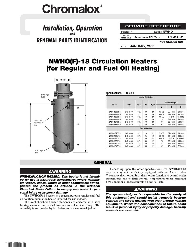
ELECTRIC SHOCK HAZARD. Disconnect all power
before installing or servicing heater. Failure to do
so could result in personal injury or property dam-
age. Heater must be installed or serviced by a
qualified person in accordance with the National
Electrical Code, NFPA 70.
To Remove Heating Element
1. Remove terminal cover screws 13 and terminal cover 3 at ter-
minal end of heater.
2. Disconnect heating element from electrical leads at both ends.
3. Remove screws 12 and nuts 10 from porcelain terminal blocks
9 and 11 .
4. Remove element support clips 7 and 15 and secondary insula-
tion bushings.
5. Lift element out of heater.
To Install Element
Observe instructions for removing element and proceed in
reverse order. Be sure to replace secondary insulation bushings.
Care of Reflectors
Reflectors should be cleaned periodically. A mild soap and
water solution or fine cleaning powder is best although more
drastic means may be required if reflectors are badly soiled by
chemical or other deposits. The reflector is aluminum. DO NOT
use alkali cleaners since alkalies will dull reflector. Mild non-
alkaline cleaners, such as used for scouring kitchen sinks, may be
used. Reflectors are replaceable and may be purchased from
Chromalox.
3
MAINTENANCE
RENEWAL PARTS IDENTIFICATION
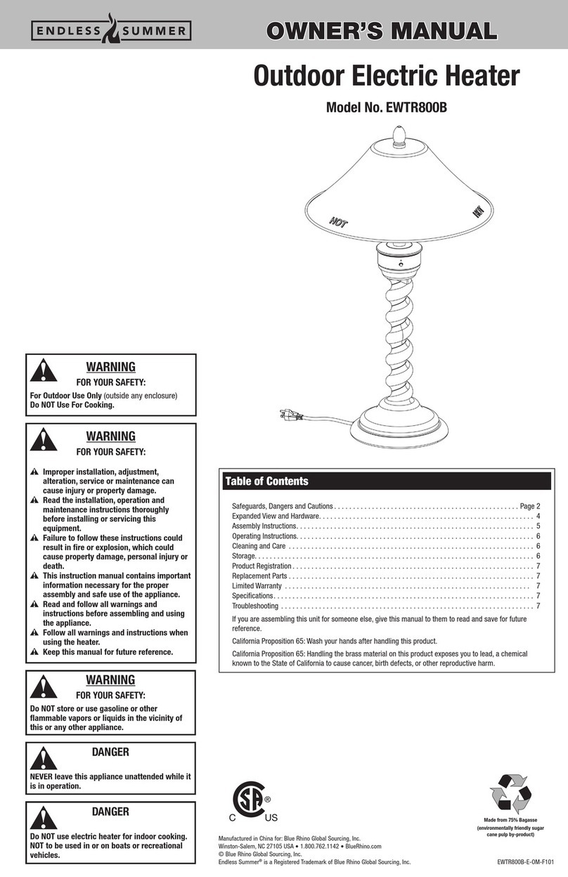
Number 1 2 6 7 15
of kW Per Element Reflector Insulation Element Bushing
Model Volts Elements Element Model No. Sheet Bushing Support Clip Retaining Clip
U-RP-410 208 or 275 3URPT-444V 234-013411-082 (3) 032-013454-001 (48) 059-014304-002 (12) 059-017175-001 (12)
240 or 480 URPT-444
4.4
U-RP-420 208 or 275 6URPT-444V 234-013411-082 (6) 032-013454-001 (96) 059-014304-002 (24) 059-017175-001 (24)
240 or 480 URPT-444
U-RP-510 208 or 275 3URPT-560V 234-013411-083 (3) 032-013454-001 (60) 059-014304-002 (15) 059-017175-001 (15)
240 or 480 URPT-560
6.0
U-RP-520 208 or 275 6URPT-560V 234-013411-083 (6) 032-013454-001 (120) 059-014304-002 (30) 059-017175-001 (30)
240 or 480 URPT-560
NOTE: Part numbers suffixed by a number in ( ) indicates the quantity of the same part number used
2150 N. RULON WHITE BLVD., OGDEN, UT 84404
Phone: 1-800-368-2493 www.chromalox.com
RENEWAL PARTS IDENTIFICATION (cont’d.)
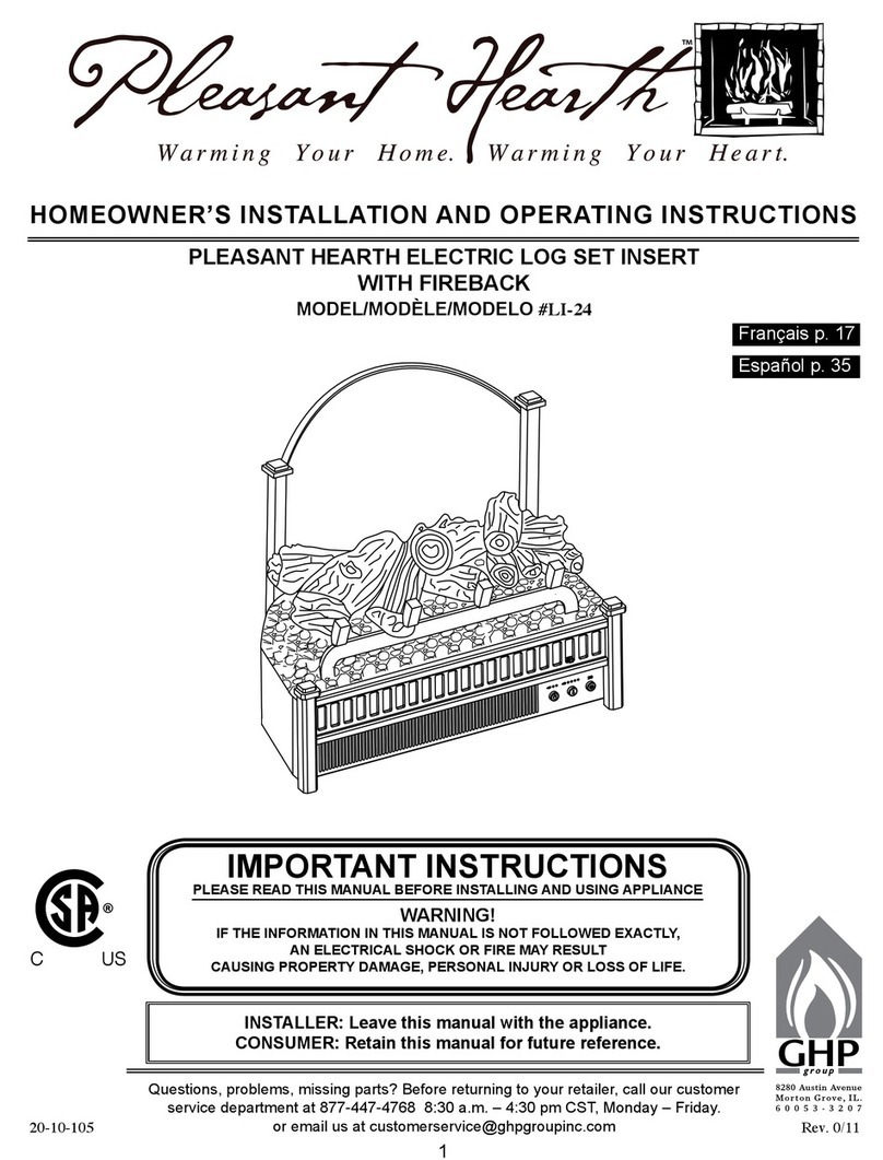
Quantity Used Per Heater
Description Part Number U-RP-410 U-RP-510 U-RP-420 U-RP-520
PARTS COMMON TO ALL HEATERS
3 Terminal Cover 306-014405-001 3 3 6 6
4 Terminal Cover Clip 056-014401-002 3 3 6 6
5 End Plates 220-016382-001 3 3 6 6
(Terminal End) 220-017278-001 3 3 6 6
8 Terminal Screw 248-046044-002 6 6 12 12
MISCELLANEOUS HARDWARE AND PARTS
9 Terminal Block 303-014317-001 3 3 6 6
10 Hexnut #8-32 200-049592-029 3 3 6 6
11 Terminal Block 303-014316-001 3 3 6 6
12 Screw #8-32 x 2-1/2” Long 248-075512-390 3 3 6 6
13 Screw #8 x 3/8” Long 248-075519-080 6 6 12 12
14 Screw #8-32 x 3/8” Long 248-075512-053 12 12 24 24
16 Saddle Clamp 238-026539-001 6 6 12 12
17 Screw 1/4-20 x 3/8” Long 248-075512-260 4 4 4 4
18 Washer 1/4” 328-075528-053 4 4 4 4
19 Hexnut 1/4-20 200-075520-070 4 4 4 4
20 Screw 10-32 x 2-3/4” Long 248-075512-419 4 4 4 4
21 Cap Screw 3/8-16 x 1/2” Long 345-115337-222 6 9 9 18
22 Lockwasher 328-024417-023 6 9 9 18
23 Screw 1/4 x 1-1/4” Long 248-075409-314 6 9 12 12
24 Screw 10-32 x 3/8” Long 248-075512-089 1 1 1 1
25 Base Plates 015-051109-001 1 1 — —
015-043319-001 — — 1 1
26 Terminal Box Covers 306-014374-001 1 1 — —
306-014374-002 — — 1 1
27 Connecting Channels 050-051107-001 2 3 — —
050-051107-002 — — 2 3
28 Terminal Box End Plate 306-014448-001 2 2 2 2
29 Bus Bar Support 219-0143800001 2 2 2 2
30 Bus Bar Support 219-014381-001 2 2 2 2
31 Bus Bar 031-051116-001 2 (1ø) 2 (1ø) — —
3 (3ø) 3 (3ø) — —
031-051116-002 — — 2 (1ø) 2 (1ø)
— — 3 (3ø) 3 (3ø)
32 Bushing (with Locknut) 032-075008-003 3 3 6 6
Limited Warranty:
Please refer to the Chromalox limited warranty applicable to this product at
http://www.chromalox.com/customer-service/policies/termsofsale.aspx.

This manual suits for next models

9

Other Chromalox Electric Heater manuals

Chromalox PF452-4 User manual

Chromalox

Chromalox PF452-4 User manual

Chromalox PG412-10 User manual

Chromalox

Chromalox PG412-10 User manual

Chromalox PF495-1 User manual

Chromalox

Chromalox PF495-1 User manual

Chromalox SRCCH-1 User manual

Chromalox

Chromalox SRCCH-1 User manual

Chromalox POO401-9 User manual

Chromalox

Chromalox POO401-9 User manual

Chromalox PF477-2 Installation and operating instructions

Chromalox

Chromalox PF477-2 Installation and operating instructions

Chromalox NWHO(F)-27 User manual

Chromalox

Chromalox NWHO(F)-27 User manual

Chromalox PG407-3 User manual

Chromalox

Chromalox PG407-3 User manual

Chromalox PD441-1 Assembly instructions

Chromalox

Chromalox PD441-1 Assembly instructions

Chromalox STAR Series User manual

Chromalox

Chromalox STAR Series User manual

Chromalox NWHO-6 User manual

Chromalox

Chromalox NWHO-6 User manual

Chromalox FXTH PN401 User manual

Chromalox

Chromalox FXTH PN401 User manual

Chromalox PG421-1 User manual

Chromalox

Chromalox PG421-1 User manual

Chromalox PD422-4 User manual

Chromalox

Chromalox PD422-4 User manual

Chromalox PB402-4 User manual

Chromalox

Chromalox PB402-4 User manual

Chromalox STAR PG434-3 User manual

Chromalox

Chromalox STAR PG434-3 User manual

Chromalox PE432-2 User manual

Chromalox

Chromalox PE432-2 User manual

Chromalox PE417-3 User manual

Chromalox

Chromalox PE417-3 User manual

Chromalox PG433-1 User manual

Chromalox

Chromalox PG433-1 User manual

Chromalox DU-RAD-458 6.04 757 User manual

Chromalox

Chromalox DU-RAD-458 6.04 757 User manual

Chromalox DS-50600 User manual

Chromalox

Chromalox DS-50600 User manual

Chromalox PF497-1 User manual

Chromalox

Chromalox PF497-1 User manual

Chromalox PG416-4 User manual

Chromalox

Chromalox PG416-4 User manual

Chromalox PG417-3 User manual

Chromalox

Chromalox PG417-3 User manual

Popular Electric Heater manuals by other brands

Rointe ZOCCA CABLE Installation and user manual

Rointe

Rointe ZOCCA CABLE Installation and user manual

Fahrenheat FBE1200 owner's manual

Fahrenheat

Fahrenheat FBE1200 owner's manual

STIEBEL ELTRON RHM 300 Operation and installation

STIEBEL ELTRON

STIEBEL ELTRON RHM 300 Operation and installation

Kroll E8 operating instructions

Kroll

Kroll E8 operating instructions

Dimplex Quantum Classic VFR 20 Installation and user instructioins

Dimplex

Dimplex Quantum Classic VFR 20 Installation and user instructioins

Ecostrad Klasse iQ instruction manual

Ecostrad

Ecostrad Klasse iQ instruction manual

Reznor EMC Series instructions

Reznor

Reznor EMC Series instructions

Starlyf RADIANT HEATER instruction manual

Starlyf

Starlyf RADIANT HEATER instruction manual

Serene LTRS7946 Installation and operating instructions

Serene

Serene LTRS7946 Installation and operating instructions

Heatscope PURE Original installation and instruction manual

Heatscope

Heatscope PURE Original installation and instruction manual

Holmes HEH8001 owner's guide

Holmes

Holmes HEH8001 owner's guide

Valor Fires 834 Installer and owner guide

Valor Fires

Valor Fires 834 Installer and owner guide

Helios EHR-R Series Fitting and operating instructions

Helios

Helios EHR-R Series Fitting and operating instructions

NuTone H-910W installation instructions

NuTone

NuTone H-910W installation instructions

HUUM STEEL Installation and operation manual

HUUM

HUUM STEEL Installation and operation manual

Trotec TDS 19 E Original instructions

Trotec

Trotec TDS 19 E Original instructions

Heat Controller IR15S Installation & operation manual

Heat Controller

Heat Controller IR15S Installation & operation manual

Kroll E 3 operating instructions

Kroll

Kroll E 3 operating instructions

manuals.online logo
manuals.online logoBrands
  • About & Mission
  • Contact us
  • Privacy Policy
  • Terms and Conditions

Copyright 2025 Manuals.Online. All Rights Reserved.