Chuphotic KR6000 User manual

KR Series UPS (6-10)KVA
User’s Manual

INDEX
1. Safety instruction..........................................................................................................- 1 -
1.1 Explanation of symbols ...................................................................................................- 1 -
1.2 Safety precautions. .........................................................................................................- 1 -
2. Overview........................................................................................................................- 5 -
2.1 Model Explanation...........................................................................................................- 5 -
2.2 Abstract of Product..........................................................................................................- 6 -
2.2.1 Product Feature .....................................................................................................- 6 -
2.2.2Technical Specifications ..........................................................................................- 8 -
3. Basic Principles and Structure.....................................................................................- 9 -
3.1 Working Principle of Single unit.......................................................................................- 9 -
3.1.1Working Principle Diagram......................................................................................- 9 -
3.1.2 Working Principle ...................................................................................................- 9 -
3.1.3Working Procedure ...............................................................................................- 10 -
3.2 Parallel System Principle...............................................................................................- 11 -
3.2.1Working Principle ..................................................................................................- 11 -
3.2.2Working Mode.......................................................................................................- 11 -
3.3 Machine Structure .........................................................................................................- 14 -
3.3.1Display structure ...................................................................................................- 14 -
3.3.2 Display interface...................................................................................................- 14 -
3.3.3 KR6000L, KR(/B)1110, KR(/B)3110 appearance..............................................- 15 -
3.3.4 KR6000, KR(/B)1110S, KR(/B)3110S appearance................................................- 17 -
4. Installation...................................................................................................................- 19 -
4.1 Installation Notice ......................................................................................................- 19 -
4.2 Installation process....................................................................................................- 20 -
4.3 Installation preparation...............................................................................................- 20 -
4.3.1 Checking the installation site................................................................................- 20 -
4.3.2 Unpacking and inspect the machine................................................................- 22 -
4.4 Machine Installation...................................................................................................- 23 -
4.4.1 Machine installation notes ...............................................................................- 23 -
4.5 Check the main input..................................................................................................- 23 -
4.6 UPS Installation..........................................................................................................- 23 -
4.6.1 KR (6&10kVA) Series UPS installation .................................................................- 23 -
4.7 Battery Cabinet Installation.........................................................................................- 25 -
4.7.1Important Security Regulation ...............................................................................- 25 -
4.7.2 Installation Steps..................................................................................................- 25 -
4.8(Parallel)System installation.......................................................................................- 26 -
4.9 Electrical connection...................................................................................................- 26 -
4.9.1 Mode of Single Unit Connection.........................................................................- 26 -
4.9.2 Wire Connection of Parallel system......................................................................- 27 -

4.10 System inspection and testing................................................................................- 30 -
4.10.1 Check electrical connections..............................................................................- 30 -
4.10.2 UPS testing .....................................................................................................- 30 -
4.10.3 Connect with the load ......................................................................................- 30 -
5. Using and Operation...................................................................................................- 31 -
5.1 Notes of using UPS.......................................................................................................- 31 -
5.2 UPS single unit operation process.................................................................................- 31 -
5.3 Operation instruction.....................................................................................................- 32 -
5.3.1 Inspection before power on..................................................................................- 32 -
5.3.2 UPS Startup Steps ...............................................................................................- 33 -
5.3.3 Start the load........................................................................................................- 33 -
5.3.4 Shutdown UPS...........................................................................................................- 33 -
5.4. Operation of Parallel system ........................................................................................- 34 -
5.4.4 Online start-up Parallel System............................................................................- 35 -
5.4.5 Redundancy and Expansion of Parallel System ...................................................- 35 -
6. Maintenance and Fault Diagnosis..............................................................................- 37 -
6.1 Maintenance Guide.......................................................................................................- 37 -
6.1.1 Safety Precaution.................................................................................................- 37 -
6.1.2 Periodic Preventative Maintenance ......................................................................- 37 -
6.2 Battery Daily Maintenance.............................................................................................- 38 -
6.3 Battery replacement......................................................................................................- 38 -
6.4 Fault diagnosis ...........................................................................................................- 39 -
6.4.1 FAQ .....................................................................................................................- 39 -
6.4.2 Troubleshooting for the failure of single units system and parallel system.............- 41 -
Appendix A. Packaging Transportation and Storage...........................................................- 42 -
A.1 Packaging.....................................................................................................................- 42 -
A.2 Transportation...............................................................................................................- 42 -
A.3 Storage.........................................................................................................................- 42 -
Appendix B Table of Toxic and harmful substance in product ...........................................- 43 -

KR series(6-10kVA)user’s manual
- 1 -
1. Safety instruction
Summary
This chapter describes the safety symbols and safety precautions. Please read this
chapter carefully before any operation of UPS in order to avoid of unsafe operation
which will endanger personal safety or equipment damage.
1.1 Explanation of symbols
Safety symbols please refer to table 1.1-1, these symbols are used to remind the
reader to abide the safety operation during the installation, operation and
maintenance
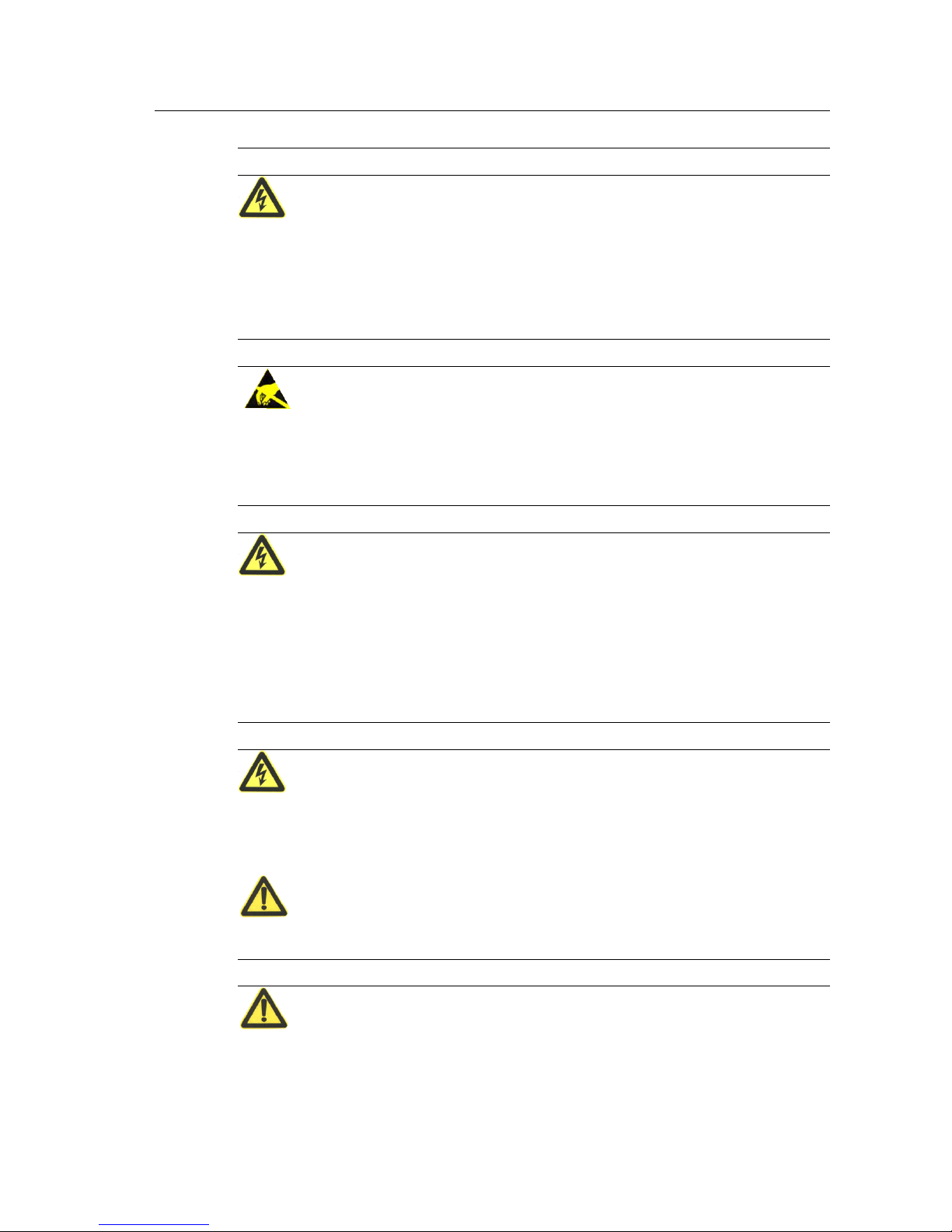
Table 1.1-1 Safety symbols and meaning
Safety symbol
meaning
Safety tips
Anti-static tips
Beware of electric shock tips
1.2 Safety precautions.
The UPS internal exists high temperature and voltage, the equipment installation, the operator
must comply with relevant safety standards and operational procedures during UPS installation,
operation and maintenance processing, or it may cause personal injury or equipment damage.
The safety precautions mentioned in the user manual only as a supplement to local safety
regulations. The manufacturer company does not responsible for any breach or violation of
general requirements of safe operation or violation safety standards of the design, production
and use of equipment.
Different brands and different types of battery charging voltage requirements are different,
make sure that the charging voltage of UPS and battery charging voltage are matched, if any
doubt, please contact the manufacturer or distributor for support. Any change of system

KR series(6-10kVA)user’s manual
- 2 -
configuration, structure or components will affect the performance of UPS, if the user wants to
make any change please consult with manufacturer or distributor in advance.
Life risk!
Contact high voltage and mains directly or indirectly through humidity objects will cause life
risk.
1.Only authorized professionals are allowed to open the UPS chassis! The UPS input and output voltage is
high risk. Contact the high voltage will bring life risk.
2.Please disconnect the AC power, battery before maintenance.
And test the output terminal block with a voltmeter before maintenance to ensure that the input is turned off
and in safe condition.
3.Even if all external power is disconnected, UPS internal capacitor exists residual electric charge, and
output terminal blocks exists high voltage which may endanger life. So it needs to put the UPS aside long
time(≥10 min), the UPS chassis could be opened after charge released.
4.Battery cable has not separated with AC input. Dangerous voltage may exist between battery terminal and
ground terminal. Battery pack exists high voltages which may endanger life, please make sure that they are
insulated when installation or use.
5.Easy conductive objects such as watches, bracelets and rings are forbidden during operation.
6.The UPS installation person should have the qualification of high voltage and AC power operation. Power
system maintenance and repair could only be done by professional person.
7.Leakage risk! The UPS must be grounded before electrical connections. The ground terminal must be
connected to the ground.
Unbalanced load, half-wave rectifier load or inductive load are not allowed to
connect to UPS output, such as air conditioner, hair dryer, starter, electric drills, motors,
fluorescent lights, ect.
Drilling holes on the cabinet is prohibited.
Inappropriate drilling will damage the device inside the cabinet. Metal debris generated by
drilling enters the cabinet will lead to PCB short circuit.
KR series(6-10kVA)user’s manual
- 3 -
It is dangerous to operate under lightning storm!
Operation under high voltage and AC operation is prohibited during a lightning storm or in the
tower or the mast operation. During a lightning storm, the atmosphere will produce a strong
electromagnetic field. Therefore, in order to avoid of equipment struck by lightning, lightning
protection should be grounded timely
Be careful of static!
To prevent static damage sensitive components, make sure that you are wearing a wrist strap
before contact with sensitive components (such as the flapper, circuit boards, IC chips, etc.),
also the other end of wrist strap is well grounded.
Installation with AC input and remove power cable are dangerous!
Installation with AC input and remove power cable are prohibited.
Please turn off main switch before assemble power cable or remove power cable. Before
connecting the cable, make sure the connection cable, cable labels are in line with the actual
installation.
Do not connect the ground wire and neutral wire, live wire and neutral wire reversely
which will cause short circuit. It should be well grounded, the voltage between ground wire and
neutral wire should be less than 5V.
Please use specified battery model!
Non-specified battery will cause damage to UPS.
Battery operation must be done according to instructions!

KR series(6-10kVA)user’s manual
- 4 -
Battery operation must be done according to the battery user manual instructions, especially for
battery wire connection. Non-standard operation will damage the battery, even endanger life.
1.Prohibit to short circuit the positive and negative of the battery. The battery connecting wires must be
tightened. Touch the battery’s every two wire connectors or bare wire terminals are prohibited, or it may
cause battery damage or endanger life.
2.Prevent the battery electrolyte overflow. The metal objects and circuit board will be corroded by the
electrolyte which will result in equipment damaged and short circuit.
3.Battery should be stayed away from fire and all the electrical equipment which could cause sparks easily to
avoid danger or unnecessary losses.
Be careful for the rotating fan!
When remove the fan, do not put fingers or tools into the rotating fans before the fan stopped in
order to avoid equipment damaged or life injured.
Keep good ventilation of the equipment!
Ensure that no objects are in the front of air-in and air-out holes and fans, to keep good
ventilation.
The product is class Aequipment!
It may cause radio interference when used in residential house, the user should use additional
measures to avoid of radio interference.
Warning label should be affixed outside UPS position area!
When UPS is failure, it still exists dangerous voltage, the warning labels should included 1.
This line is for UPS power supply. 2. Please disconnect this line before line operation.

KR series(6-10kVA)user’s manual
- 5 -
2. Overview
Summary
This chapter introduces the model name meaning of the device, system characteristics and
performance index.
2.1 Model Explanation
The meaning of KR 6kVAseries model name is shown as Pic. 2.1-1.
KR L
6000
Long Back Up Model
Output Power
KR Series Online UPS
Fig.2.1-1 The meaning of KR 6kVAseries model name
Shown as Fig. 2.1-1, “KR” indicates that this product is Kehua KR Series high frequency UPS; “6000”
indicates that output power of this product is 6kVA; “L” indicates that this product is long back up model,
if without “L” means it’s standard model.
The meaning of KR 10kVAseries model name is shown as Pic. 2.1-2.
KR/B * 1 ** S
Standard Model
Output Power
Single Phase Output
Input Phase
Parallel Model
KR Series Online UPS
Fig. 2.1-2. The meaning of KR 10kVA series model name

KR series(6-10kVA)user’s manual
- 6 -
Shown as Fig. 2.1-2, “KR” indicates that this product is Kehua KR Series high frequency UPS;
“/B” indicates that this product is parallel model; if without “/B” it’s standard model; output
phase “1” indicates that it’s single phase output; output power “**” indicates the output power
of this product; when it’s “10”, it indicates that the output power is 10kVA; “S” indicates that
this product is standard model, if without “S”, it’s long back up model.
2.2 Abstract of Product
2.2.1 Product Feature
KR series (6&10kVA) UPS are online UPS of sine wave charactering high-performance, especially designed
for network computer room, small intelligent equipments like measure devices or industrial auto-machines
etc. and precise instruments used in systems such as finance, communication, insurance, transportation,
taxation, military, stock, energy, education, government and enterprises etc, specially for terrible electric
network circumstance.
KR series (6&10KVA) UPS, the online UPS of sine wave charactering high-performance has mainly the
following features:
Great adaptability for AC input
Within wide input voltage range, there is no need for battery supply which can effectively protect batteries.
Precise synchronization system with AC input
The realization of exact zero-phase synchronization between output and input can meet the requirement to
synchronization of power supply and electric network from a variety of instruments, being propitious to
improve user system performance and boosting the reliability of bypass switch.
High input power factor
Adopt advanced active PFC technique, single phase input power factor could reach 0.99, 3 phase input power
factor could reach 0.95, which further alleviates load on electric network and represents green power supply
of new generation.
High performance with competitive price
Adopt multiple power transfer and high frequency PWM technique, character high efficiency, small size and light
weight, improve running reliability and reduce manufacturing cost. All above help decreasing customer cost
of system designation.
Low running input voltage

KR series(6-10kVA)user’s manual
- 7 -
Independent fast-test technique adopted leads to no inversion of DC/DC module even when input voltage
lows to limit 120V so that all the output energy under the commercial supply status is transferred from
electric network that can guarantee the batteries are in 100% energy-storage status and decrease
battery-discharge number to prolong life.
Perfect protection function
Functions designed such as output high voltage protection, low battery protection, over load protection, fast
current-limit, short-circuit protection, over temperature etc are able to avoid faults caused by manual
operation mistake to guarantee reliable work in different conditions.
Intelligent RS232 and USB communication function (optional)
With RS232 or USB standard data interface, supported by UPSilon 2000 power monitor software, the status
of electric network and UPS can be directly inspected on the computer monitor. The product can also support
SNMP network adaptor which will make the UPS as newcomer of network immediately, realizing network
administration and improving system reliability.
KR series(6-10kVA)user’s manual
- 8 -
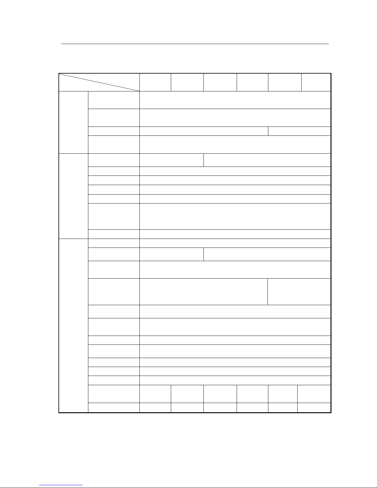
2.2.2Technical Specifications
Table 2.2-1 KR Series (6-10KVA) Main Technical Specification
Model
Index
KR6000
KR6000L
KR1110S
KR/B1110S
KR1110
KR/B1110
KR3110S
KR/B3110S
KR3110
KR/B3110
Input Characteristic
Rating voltage (V)
120~140Vac half full load, 140~160Vac 75% full load,
160~276Vac 100% full load
Rating Frequency
(Hz)
50±10%
Phase
Single-phase three-line
Three-phase fiv-line
Battery voltage
(Vdc)
192
Output Characteristic
Capacity (VA/W)
6kVA/4.8kW
10kVA/8kW
Voltage (V)
220±2%
Frequency (Hz)
50±0.1%(Battery mode)
Waveform
Sine wave,,THD<3%
transfer time(ms)
0
Overload capacity
105%-130% rating load ,last 10min then turn into bypass
130%-150% rating load ,last 1min then turn into bypass
Above150% rating load ,last 1 sec then turn into bypass
Output Mode
Terminal
Other Characteristic
Back up Time
Configure optionally
Charge recovery time
<20 H(100AH a group)
<20 H(100AH a group)
Communication
interface
RS232/USB interface supports Upslion 2000 software and
SNMP protocol (optional)
Alarm
AC fail, low battery, Overload, Over temperature. UPS
fault, Incorrect input connection of phase-sequence
AC fail, low battery,
Overload, Over
temperature. UPS fault,
EPO function
when the EPO signal is off, output is off
Maintenance bypass
(optional)
with manual maintenance bypass, convenience for uninterruptible maintenance
Panel display
LED displays operation status and LCD displays parameter
Audio-noise (dBA)
<65
Protection function
Low battery, over voltage, overload, short-circuit and over temperature.
Working temperature
0~40℃
Relative humidity
0~95%,No condensation
Size (mm)
(W × D × H)
255×565×
700
255×565×
500
255×565×
700
255×565×
500
255×565×
700
255×565×
500
Weight (Kg)
69
23
70
24
71
27
Specifications are subject to change without prior notice.

KR series(6-10kVA)user’s manual
- 9 -
3. Basic Principles and Structure
Summary
This chapter mainly introduces the principle and overall structure of KR Series (6&10kVA) UPS, including
the display meanings of panel indicator lights and definitions of external interface.
3.1 Working Principle of Single unit
3.1.1Working Principle Diagram
CHARGE
PFC AC/DC SW
BATTERY
DC/DC
DC/AC LOAD
AC INPUT
Fig.3.1-1 KR Series Working Principle Diagram
3.1.2 Working Principle
UPS KR(6-10)KVA is made up of PFC, AC/DC (Commercial power rectification and boost
circuit), DC/DC (battery voltage-boost circuit), DC/AC inverter, switch, charger and battery
group etc.
When commercial power is normal, through PFC, it can be boosted to stabilized DC supplied
for DC/AC inverter to output steady 220VAC and finish battery charge at the same time. When
commercial power is abnormal, through DC/DC, the battery voltage will be increased to
stabilized DC supplied for DC/AC inverter. Because of PFC and power-down fast-test
technique adopted, even when the commercial power voltage lows to limit 120V, the battery
group can still have no output current to assure battery longevity and be kept in energy-storage
status and if commercial abnormal battery voltage-boost will start up at once to assure steady
DC/AC output.
As shown in the Figure 3.1-1, the DC/AC inverter adopts half-bridge structure, DC/DC module
uses boost-circuit, PFC is active power-factor correction circuit and CHARGER is a kind of
complete isolation charger.

KR series(6-10kVA)user’s manual
- 10 -
3.1.3Working Procedure
When 220Vac normal, main DC circuit has DC voltage supplied for DC-AC AC-inverter which
outputs stable 220Vac and charges battery at the same time. Whenever commercial power was
low or broken down suddenly, the battery group would feed back electric power to DC circuit
through DC/DC voltage-boost module. There is no transfer time from mains supply to battery
supply. When batteries’ energy is used up, UPS would send out audio-light warning till battery
voltage drop to the discharge limitation point then UPS would stop inversion and emit lasting
sound. In addition, UPS has overload protection. When overload (125% full load) happens,
UPS would turn to bypass supply and return if load recovers normal. When more serious
overload (over 150% full load) appears, UPS would halt inversion and switch to bypass
supply-at the time the switch may have jumped. After fault of load eliminated, as long as turn
on the switch, UPS will restart to work again. Audio-light warnings will always go with UPS
when UPS abnormal. The warnings or protections are shown in detail in Table 3.1-1.
Table 3.1-1 The Functions ofAbnormal Status and Warning Protections
UPS Status
Beep
Indicators On Panel
LCD Display
Protection
/Warning
Normal
No beep
INV. On, Line on,
Bypass off, Fault off,
Output on
“Output Voltage
220.0 V ”
No.
105% overload
Once every 1.5 sec
INV. On, Bypass off,
Fault off, Output on.
“Output 220.0V
OVERLOAD ”
Turn to bypass
supply in 10 min
125% overload
Long beep
Bypass on, INV. Off,
Fault on, Output on in 1
min
“Output 220.0V
OVERLOAD ”
Turn to bypass
supply in 10 min
150% overload
Long beep
INV. Off, Bypass on,
Fault on, Output on
“Output 220.0V
LOAD PROTECT”
Protected
Low-voltage point
Once every 0.5 sec
INV. On, Line off,
Bypass off, Fault off,
Output on
“Output 220.0V
BAT. LOW ”
Waning
Battery voltage below
protection point
Long beep
INV. Off, Line off,
Bypass on, Fault on,
Output off.
“Output 220.0V
BAT. PROTECT”
Protected
Input breaker cutoff or
input abnormal
Three beep with
100ms interval every
10 sec
INV. On, Line off,
Bypass off, Fault off,
Output on
“Output 220.0V
LINE FAIL”
Warning
Over temperature
Long beep
INV. Off, Line off,
Bypass on, Fault off,
Output on
“Output 220.0V
OVER TEMP”
Protected
Output over-voltage,
Output low-voltage
Long beep
INV. Off, Bypass on,
Fault on, Output on
“Output 220.0V
INVERTER FAIL”
Protected
KR series(6-10kVA)user’s manual
- 11 -
Short-circuit
Long beep
INV. Off, Bypass on,
Fault on, Output on
“Output 220.0V
OUTPUT SHORT”
Protected
Note: If commercial power recovers after low-voltage protection to battery, the product will restart and charge batteries.
3.2 Parallel System Principle
3.2.1Working Principle
Parallel flow equalization of AC input is mainly through rapid adjustment of paralleled single’s
output waveform, amplitude and phase, then make them strictly the same, to achieve current
sharing purposes. Any difference of the voltage amplitude or phase may have a great
circulation; seriously, it may cause overload or inverter damage. As the high-power UPS itself
may have large interference, therefore, parallel systems must have strong anti-interference
features, thus ensure the system reliability service.
3.2.2Working Mode
Diagram of Parallel system is shown as Fig.3.2-1.
PFC
DC/ DC
PFC
DC/ DC
Bypass Switch
Inverter
Load
Battery
Main(UPS2)
AC Input
Bypass Switch
Inverter
Battery
Main(UPS1)
Fig.3.2-1 Diagram of Parallel System

KR series(6-10kVA)user’s manual
- 12 -
Parallel units all have independent bypass, two UPS can directly parallel without parallel control cabinet or
extra public bypass input, so that they are easy to install and maintain.
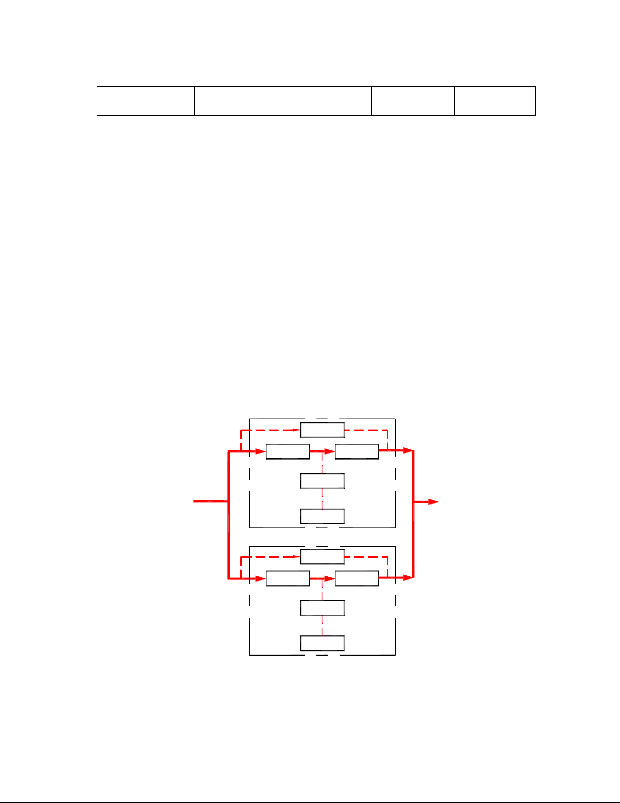
There are below four main working modes of parallel system:
1、Working mode of utility normal (solid line is Energy flow of UPS) as shown in Fig.3.2-2.
DC/ DC
PFC
PFC
DC/ DC
Bypass Switch
Inverter
Load
Battery
Main(UPS2)
AC Input
Bypass Switch
Inverter
Battery
Main(UPS1)
Fig 3.2-2 Working mode of utility normal
2、Working mode of utility abnormal (solid line is Energy flow of UPS) as shown in Fig.3.2-3.
PFC
DC/ DC
DC/ DC
PFC
Bypass Switch
Inverter
Battery Load
Main(UPS2)
Bypass Switch
Inverter
Battery
Main(UPS1)
AC Input
Fig3.2-3 Working mode of utility abnormal
KR series(6-10kVA)user’s manual
- 13 -
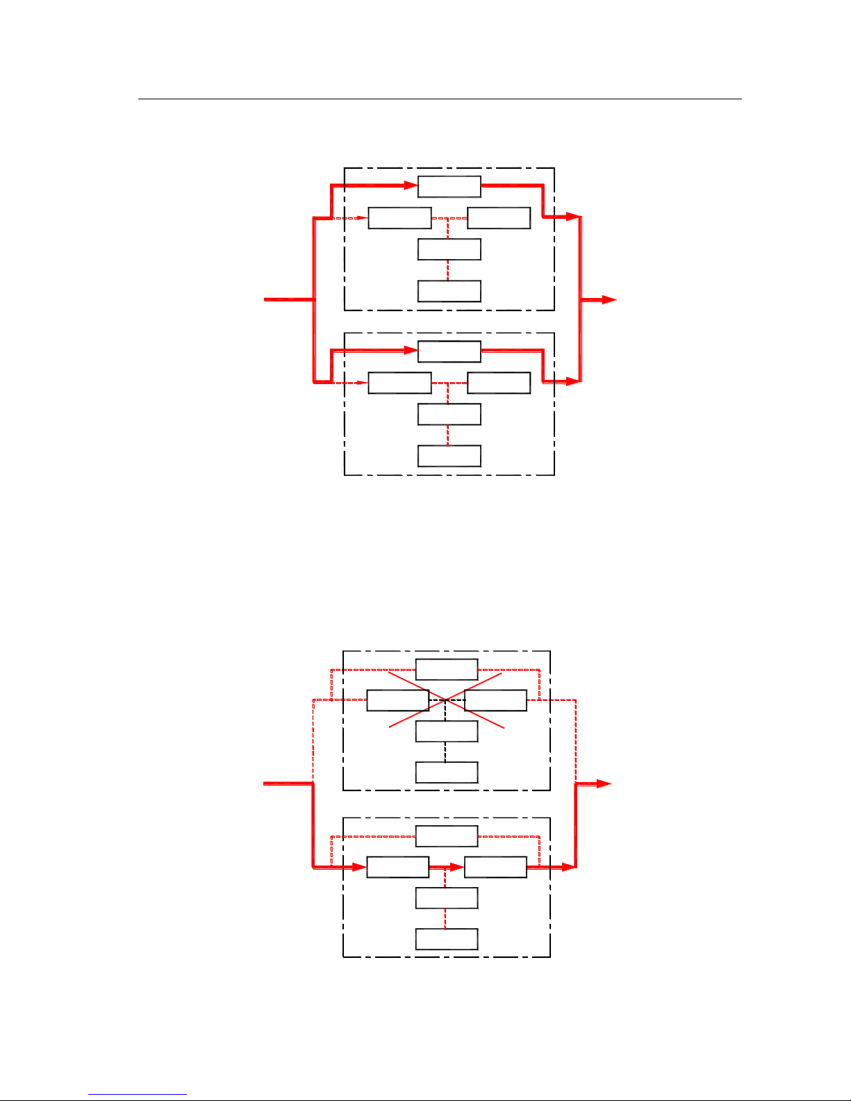
3、Working mode of overload (solid line is Energy flow of UPS) as shown in Fig.3.2-4.
PFC
DC/ DC
DC/ DC
PFC
Bypass Switch
Inverter
Load
Battery
Main(UPS2)
AC Input
Bypass Switch
Inverter
Battery
Main(UPS1)
Fig.3.2-4 Working mode of overload
4. Working mode of one machine abnormal (solid line is Energy flow of UPS) as shown in
Fig.3.2-5. Abnormal machine doesn’t have output, so supply power to load only by normal
machine.
PFC
DC/ DC
DC/ DC
PFC Inverter
Battery Load
Main(UPS2)
Bypass Switch
Bypass Switch
Inverter
Battery
Main(UPS1)
AC Input
Fig.3.2-5 Working mode of single machine abnormal
KR series(6-10kVA)user’s manual
- 14 -
3.3 Machine Structure
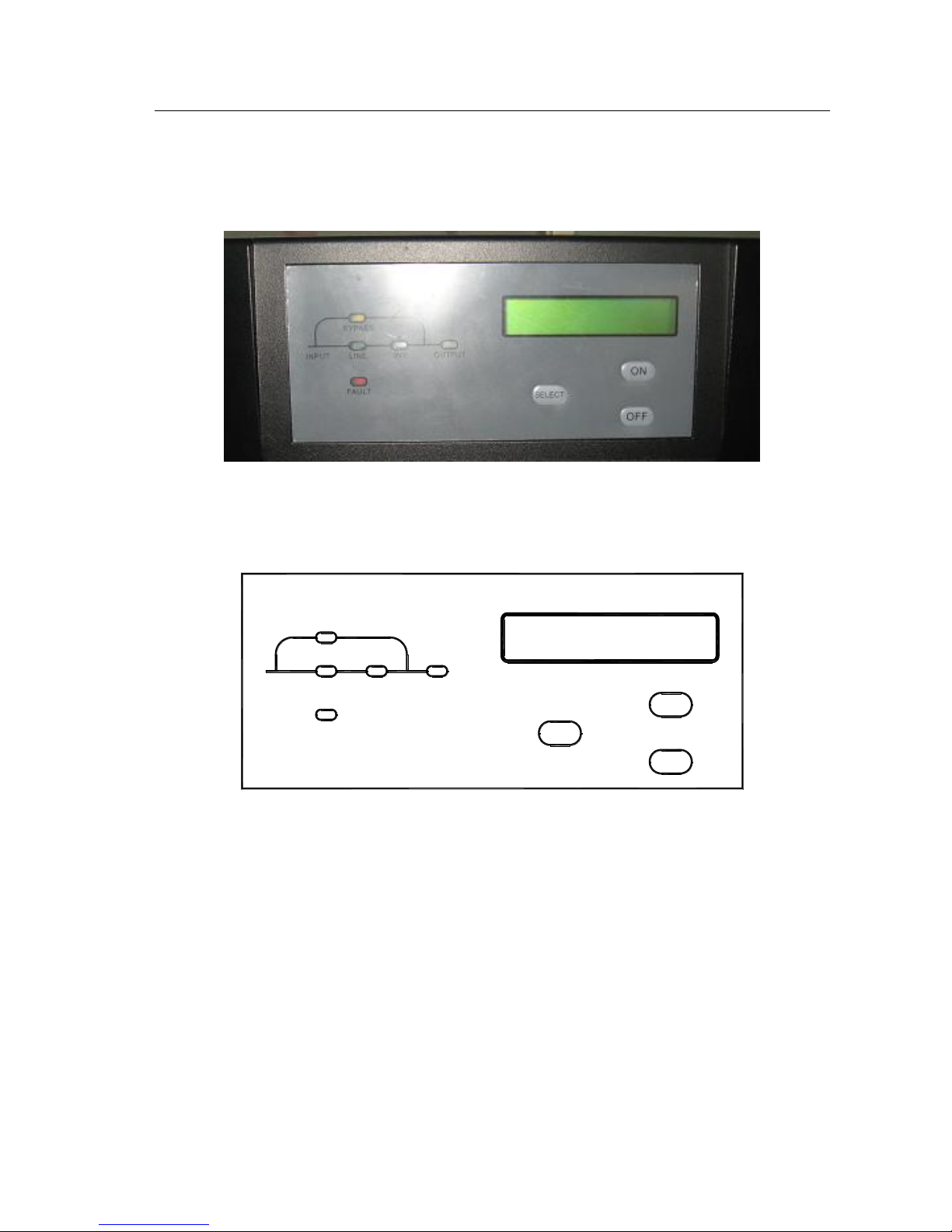
3.3.1Display structure
3.3-1 KR Series 6&10KVA display panel
3.3.2 Display interface
INV.LINE
BYPASS
OUTPUT
SELECT
ON
OFF
FAULT
INPUT
①②③
④
⑤
⑥
⑦⑧
⑨
3.3-2 KR 6&10KVA display interface
LCD display illustration:
① “LINE” : When commercial power is normal, light on; abnormal, light off; when live wire
and neutral wire reverse, light fliter (three phase in single phase out type is without this
function ).
② “INV.” : Inverter normal, light on; abnormal, light off
③ “OUTPUT” : UPS has output, light on; no output off.
④ “BYPASS” :UPS in status of bypass supply, light on; in status of inversion, off.
⑤ “FAULT” :UPS fault, light on; normal, off.
⑥LCD Display panel.

KR series(6-10kVA)user’s manual
- 15 -
⑦ “Select”: When UPS is normal, LCD displays normal output voltage. If the button pressed,
the background light on and the LCD display will show input voltage, input frequency, output
power, UPS status etc.
⑧“ON” :When UPS is shutdown, press the button for 1 sec, UPS starts up. When UPS is
running, press the button for 1 sec, UPS will enter battery test model. When battery voltage
reaches the low-voltage point or test time last 10 sec, UPS will stop the function. When battery
is working of INV., press the button for 2 sec, the buzzer will stop the discontiguous beep, but
the warning is not eliminated of battery low-voltage etc.
⑨“OFF” :When UPS is running, press the button for 1 sec, UPS will shut down.
3.3.3 KR6000L, KR(/B)1110, KR(/B)3110 appearance
3.3-3 KR 6000L, KR (B)1110, KR(/B)3110 appearance

KR series(6-10kVA)user’s manual
- 16 -
DISPLAY
AIR
INLET
INV.LINE
BYPASS
OUTPUT
SELECT
ON
OFF
FAULT
INPUT
⑩
④②
①
③
⑤
⑥
⑦
⑧⑨
OFF
BATTERY
ON
POWERBYPASS
EPO USB RS232 RS232
USB
EPO
SNMP
(optional)
POWER Breaker
BATTERY Breaker
BYPASS Breaker
FANS
LINE BAR
COVER
MANUAL
MAINTENANCE
BYPASS
(optional)
OFF
BATTERY
ON
POWERBYPASS
EPO USB RS232 RS232
USB
EPO
FANS
LINE BAR
COVER
MANUAL
MAINTENANCE
BYPASS
(optional)
SNMP
(optional)
POWER Breaker
BATTERY Breaker
BYPASS Breaker
PALL. PALL.
Front panel KR6000L rear panel KR(/B)1110, KR(/B)3110 rear panel
3.3-4 KR6000L, KR(/B)1110, KR(/B)3110 Front Panel and Rear Panel

KR series(6-10kVA)user’s manual
- 17 -
3.3.4 KR6000, KR(/B)1110S, KR(/B)3110S appearance
3.3-5 KR6000, KR(/B)1110S, KR(/B)3110S appearance
This manual suits for next models
9
Table of contents
Other Chuphotic UPS manuals


