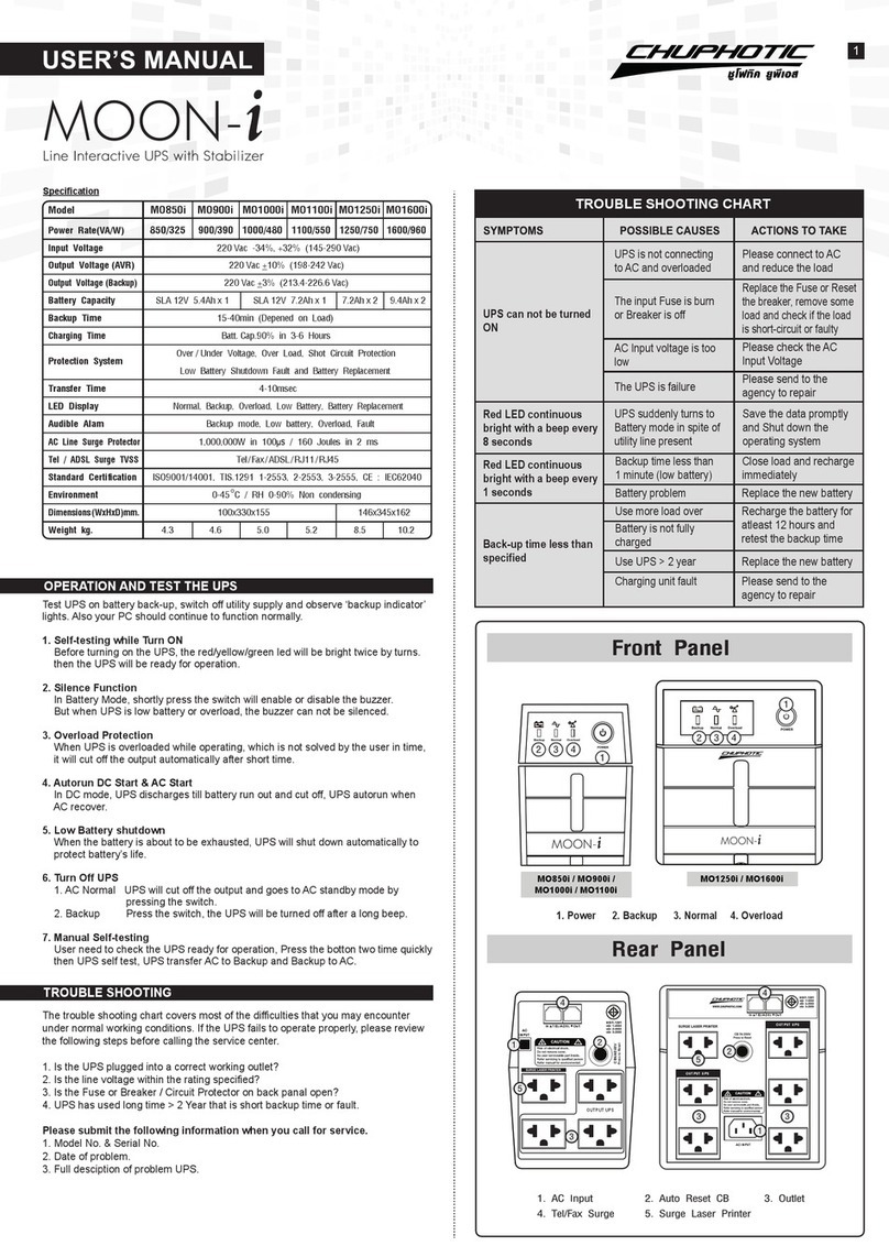
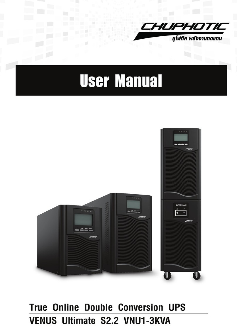
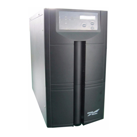
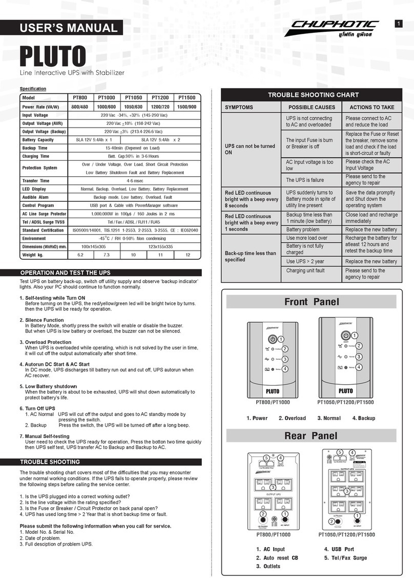
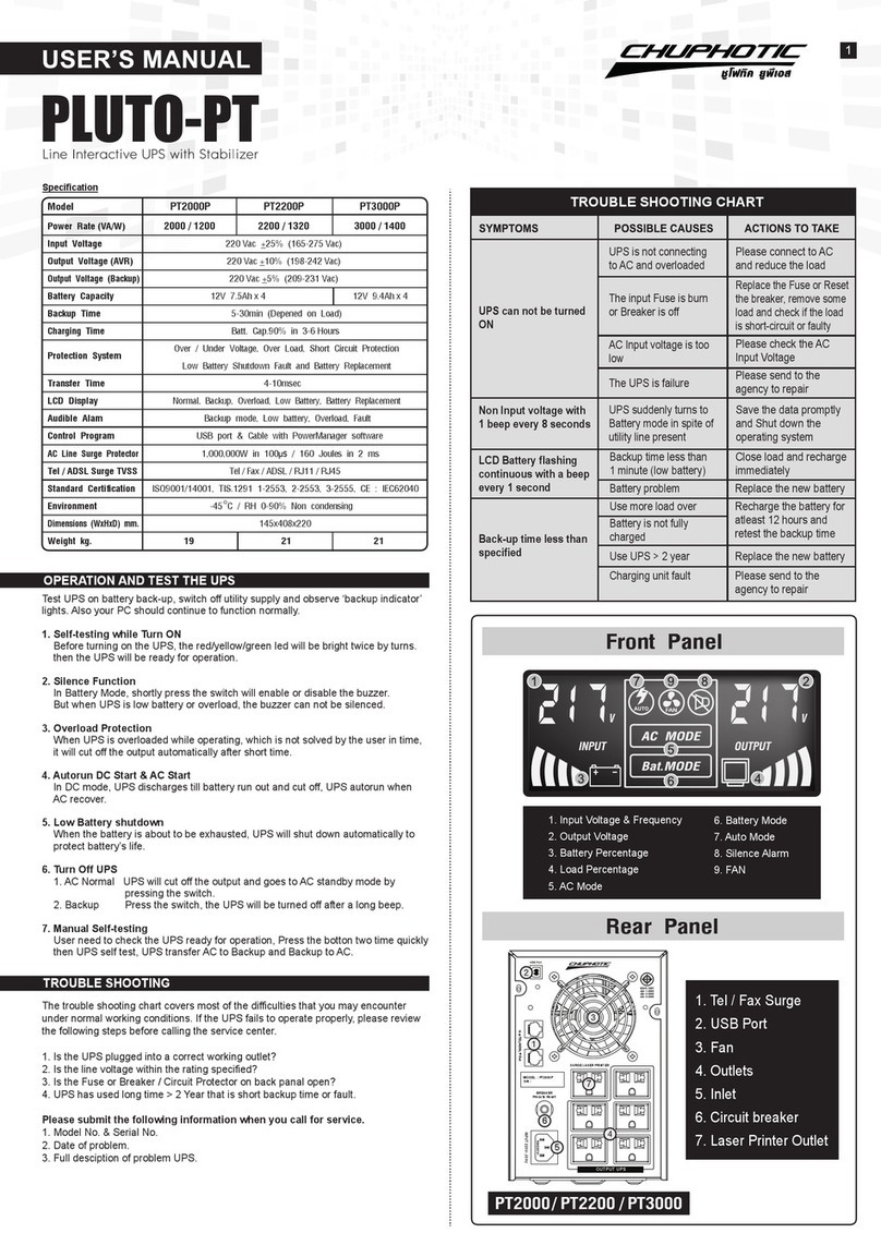
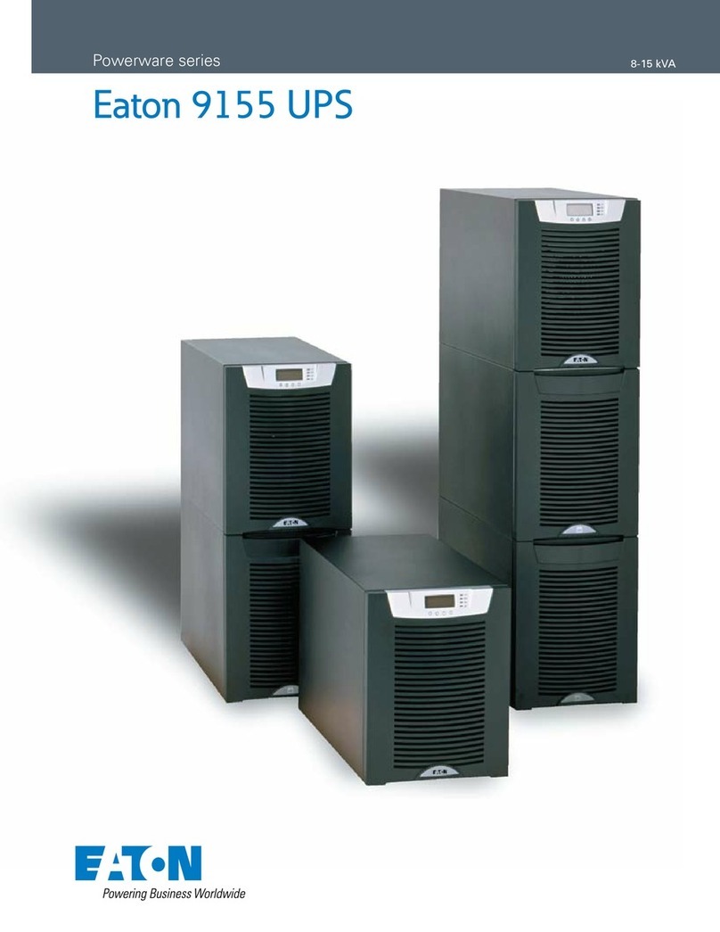
Chuphotic Venus Smart 1K User manual

User's Manual
ชูโฟทิค กรุ๊ป
บริษัท ชูโฟทิค จำ�กัด
บริษัท เอ็นเนอร์ยี่ เวฟ จำ�กัด
บริษัท ชูโฟทิค อิเล็กทรอนิกส์ จำ�กัด
949 หมู่ 9 ต.สำ�โรงเหนือ อ.เมืองสมุทรปร�ก�ร จ.สมุทรปร�ก�ร 10270
โทร. 02 186 3011 แฟกซ์: 02 186 3018-19
เว็บไซต์: www.chuphotic.com อีเมล์: [email protected]
CHUPHOTIC GROUP
CHUPHOTIC CO.,LTD.
ENERGY WAVE CO.,LTD.
CHUPHOTIC ELECTRONICS CO.,LTD.
949 Moo 9, Sumrong-Nue, Muang Samutprakarn, Samutprakarn 10270
Tel. 02 186 3011 Fax. 02 186 3018-19
TRUE ONLINE DOUBLE CONVERSION UPS
user manual Venus Smart Rev.1.00 2014

Contents
1. Introduction 1
1.1 Description of Commonly Used Symbols .................................................. 1
1.2 Safety Instructions ...................................................................................... 1
2. Product Description 2-3
2.1SystemTypeandConguration.................................................................. 2
2.2 The Appearance of the UPS........................................................................ 2
2.3OperatingPrinciple..................................................................................... 3
3. Installation 4-5
3.1UnpackingInspection ................................................................................ 4
3.2InstallationNotes ....................................................................................... 4
3.3CableConnection....................................................................................... 4-5
4. Operation (LCD model) 6-10
4.1OperationDisplayPanel ............................................................................ 6
4.2OperationMode ......................................................................................... 6-8
4.3OperatingInstructions................................................................................ 9-10
5. Maintenance 10-11
5.1BatteryMaintenance................................................................................... 10
5.2CheckingUPSfunction ............................................................................. 11
6. Troubleshooting 12-13
7. Specications 14-15
7.1Electrical..................................................................................................... 14
7.2Mechanical................................................................................................. 15
7.3Environmental............................................................................................ 15
7.4EMC........................................................................................................... 15
7.5Safety.......................................................................................................... 15
7.6IndustryStandard....................................................................................... 15
8. Appendix 16
8.1ConsignmentLists...................................................................................... 16

1
1. Introduction
1. 1 Description of Commonly Used Symbols
Someorallofthefollowingsymbolsmaybeusedinthismanualandmayappearinyourapplicationprocess.
Therefore,allusersshouldreadtheformcarefullyandthoroughly.
1. 2 Safety Instructions
1. ReadthismanualcarefullyandthoroughlybeforeoperationtheUPSandsavethismanualproperlyfor
future reference.
2. Do not tear up or shatter the alarm table on the UPS and pay attention to it.
3. Please do not overload the UPS.
4. TheUPScontainslargecapacitybatteries.ThecaseoftheUPSmustnotbeopenedbyuntrainedpersonnel.
Otherwise, it may cause electric shock.
5. Donotshortthepositiveandnegativeelectrodesofbattery.Otherwise,itmaycauseelectricshockorre.
6.Donotplungeorinsertanyobjectsintotheairventsandotherinlets.
7.Donotstoreorusethedeviceinthefollowingenvironment:
• Wherethereisinammablegas,corrosiveagentsorheavydust
• Wherethetemperatureisveryhighorlow(above40oCorbelow0oC)orthehumidityisveryhigh
(morethan90%)
• Underdirectsunlightorclosetoheatingfacilities
• Placeofstrongvibrations
8. Intheeventofreoccurringinthevicinity,pleaseusedrypowderreextinguishers.Theuseofliquid
reextinguishingagentsmaycauseelectricshock.
Symbol & Description
Symbol Description
Caution,danger
Dangerelectricshock
Alternatingcurrent(AC)
Directcurrent(DC)
Protectiveground
Recycle
Do not dispose with ordinary trash

2
2. Product Description
TheUPSisanon-lineuninterruptiblepowersupplydeviceincorporatingdouble-convertertechnologywith
single-phaseinputandsingle-phaseoutput.Itoffersthehighqualitypowersupplywiththegreatestdegreeof
availabilityandreliability.TheUPSiscompactandconvenientforusers,especiallyforthebasicequipments
insomeareassuchas:nance,communication,government,trafc,manufacture,educationandsoon.
2. 1 System Type and Conguration
TherearetwotypesofUPSaccordingtothebatteryconguration:standardtypeandlongbackuptimetype,
eachavailableinthefollowingratings:1kVA,2kVAand3kVAUPS.
Table2-1UPStypesandcongurations
Note: “L” model means Long Backup Time.
Type Model Remark
1K Witha1Ainternalchargerand3build-inbatteriesof12V/7AH.
2K Witha1Ainternalchargerand6(or8)build-inbatteriesof12V/7AH.
3K Witha1Ainternalchargerand8build-inbatteriesof12V/7AH.
1K/1KL Witha6.5Ainternalchargerandexternalbatteryslot.
2K/2KL Witha5.5Ainternalchargerandexternalbatteryslot.
3K/3KL Witha5.5Ainternalchargerandexternalbatteryslot.
Standard
LongBackup
Time
2. 2 The Appearance of the UPS
* The picture for back panel is just for reference, it subjects
to change on customer’s requirement, please refer to the
real subject.
• Figure 2-2 The rear panel of 2K/2KL, 3K/3KL
Note: The appearances above are examples with the long
backup time, the corresponding standard type is without the
“External Battery slot”.
• Figure 2-1 The rear panel of 1K/1KL
RS232 SNMPcard
Output
terminal
Outlet
Input
RS232 SNMP
card
Outlet
External
Battery
External
Battery
Input
Circuit
Breaker
Circuit
Breaker

3
2. Product Description
2. 3 Operating Principle
1. Input lter:itlterstheinputandprovidescleanACpowertotheUPS.
2. AC/DC converter:InNormalmode,itconvertstheACinputpowertoregulatedDCpower,andraises
theregulatedDCvoltageforDC/ACconverter.
3. DC/DC converter:RaisestheDCVoltagefromthebatterysystemtotheoptimumoperatingvoltageforthe
inverterwhentheUPSoperatesinBatterymode.
4. DC/AC inverter:InNormalmode,itutilizestheDCoutputoftheAC/DCconverterandinvertsitinto
precise,regulatedsinewaveACpower.InBatterymode,itreceivesenergyfromthebatterythroughthe
DC/DCconverter.
5. Bypass:ItisveryimportantintheUPSsystem.Intheevent of a UPS fault that will not lead to UPS
shutdown,theloadwillbeautomaticallytransferredtothebypass.Meanwhile,theLEDindicatorswill
indicatethefaulttype,andthefaultinformationwillbereportedthroughthecommunicationports.
6. Charger:ThechargerofstandardUPSprovides1Achargingcurrent;andlongbackuptimeprovided1Kis
6.5Aand2K/3Kis5.5Achargingcurrent.
7. Battery:Sealedmaintenance-freelead–acidbatterycanbeusedastheDCsourceoftheUPS.
8. Output lter:ItlterstheoutputandprovidescleanACpowertotheload.
Bypass
Battery
Inputlter Outputlter
AC/DC
converter
AC/DC
converter
AC/DC
inverter
Charger
Input Output
• Figure 2-3 The UPS operating principle

4
3. Installation
3. 1 Unpacking Inspection
1.OpenthepackingboxofUPSandtakeitout,visuallyexaminetheunitfortransitdamage.
2.CheckagainsttheaccessoryliststhattheaccessoriesoftheUPSarepresent.(RefertoTable9-1).
3.Makesurethemodeliswhatyouwantedfromthenameplateontherearpanel.
4.IftheUPSarrivesdamaged,orthereisanymissingaccessoryorotherquestionabove,pleasecontactthe
distributor immediately.
3. 2 Installation Notes
1.When locating the UPS, make sure there is no hazardous objects such as water, inammable
gas, corrosive agents and so on around the UPS, and that the installation environment meets the
specications.
2. The UPS should not be placed on a side. The air inlet port at the front panel and the outlet port on the
rearpanelandtwosidepanelsshouldnotbeblockedsoastoensuregoodventilation.
3. In case if the UPS is unpacked, installed and used at very low temperatures, condensations of water drops
mayappear.ItisnecessarytowaituntiltheUPSfullydriedinsideoutbeforeproceedingtoinstallation
and use. Otherwise, they may be a risk of electric shock.
4.PlacetheUPSneartheutilitypowersourceoutletwhichsuppliespowertotheUPS.Inanyemergency,
switchoffthemaininputsocket,cutoffthebatteryvoltageinput.Allpowersocketsmustbeconnected
withgroundprotection.
3. 3 Cable Connection
3.3.1ConnectingInputandOutputCables
1. Input cable connection
If the UPS is connected via the power cable, please
use a proper socket with over current protection,
and pay attention to the capacity of the socket:
over 10A for 1K/L, over 16A for 2K/L and
3K/L. side of input wiring has been xed with
theUPS,andtheothersideisjustneedtoplug
into the input socket. The wiring conguration
isshowninthefollowingdiagram.
2. Output cable connection
Theoutputof1K/L,2K/L,3K/Lallavailableto
uses sockets. The total output power shall not
exceed1kVA/0.8kW/0.9kW,2kVA/1.6kW/1.8kW,
3kVA/2.4kW/2.7kW.Simplyplugtheloadpower
cable to the output sockets of UPS to complete
connectionasshowninthefollowingdiagram.
• Figure 3-1 Connection Method of Input
• Figure 3-2 Connection method of output
LOAD

5
3. Product Description
3.3.2 Operation Procedure of External Battery for Long Backup Time UPS
Thebatteryconnectionprocedureisveryimportantforlongbackupmodel.Anyincompliancemayresultin
theriskofelectricshock.Therefore,thefollowingstepsmustbestrictlycompliedwith.
1. First connect in series the batteries of the pack
toensureproperbatteryvoltagethat1K/1KLfor
36VDC, 2K/2KL for 72VDC (or 96VDC),
3K/3KLfor96VDC.
2. Take out the battery cable delivered with the
UPS,oneendoftheexternalbatterycableisa
plugforconnectingtheUPS,theotherendhas3
openwiresforconnectingthebatterypack.
3.Connecttheexternalbatterycabletothebattery
terminal(DONOTconnectthebatterysocketof
theUPS rst. Otherwise,it may causeelectric
shock). Connect the red wire to the “+”
terminal of the battery. The black wire is
connected to the “-” terminal of the battery.
Thegreen/yellowwireisgroundedforprotection
purpose.
4.Connect the plug of the external battery cable to the external battery slot on the rear panel of the
UPS to complete the connection procedure.
Note: The length of the external battery cable is 1.6 m, If users need a longer one, please consult the
distributor. There is a limit to the length of the external battery cable to ensure normal operation of the UPS.
3.3.3 Connecting Communication Cable
1. Computer interface
Computerinterface:Thetypeofsignalsisprovided
by the UPS to communicate with a host computer
through communication cable included in the
standard accessory, User can use special monitor
software UPSilon in the standard accessory to monitor
theUPSthroughtheport.
2. Alternative connection of communication
Intelligent Slot: It is designed for installing the dry
contact card, SNMP card and 485 card. You can
choose for one of them to installed.
a-drycontactcard:Youcanutilizemonitorfunction
ofdrycontacttomanagethepowersupplydirectly.
b-SNMP:ItenablesyoumonitortheUPSremotely
throughInternet.
c-485:Centralmonitorcard.
Note: Please remove the cover board of the intelligent
slot before any card is installed.
• Figure 3-3 Battery connection diagram for
LongBackuptimemodels
BATTERY BANK UPS
•Computercommunicationcable
RS-232
RS-232
•SNMPCardSlot
SNMP Card

6
4. Operation (LCD model)
4.1 Operation Display Panel
1. ON button:
PressingtheONbuttonmorethan1second(buzzerbeepsonce),theUPSsystemisturnedon.
2. OFF button:
Bypressingthisbuttonmorethan1second(buzzerbeepsonce)turnsofftheUPSsystemwhenever
theUPSrununderthenormalmode/batterymode.
3. Function button
TheFunctionbuttonprovidesthefollowingfunctions:
a) Battery self- diagnosis: When the UPS ran in normal mode, pressing this button more than 2
seconds(buzzerbeepstwice)canstartthebatteryself-diagnosis.
b) Silencefunctioninbattery/bypassmode
Inbattery/bypassmode,whenthebuzzerbeeps,pressingandholdingthefunctionbuttonformorethan
2seconds(buzzerbeepstwotimes)cansilencethebuzzer.Pressthebuttonformorethan2seconds
(buzzerbeepstwice)againtoresumethealarmfunction.
c) LCDdisplayscreenswitch
Pressingthefunctionbuttonformorethan1secondsandlessthan2seconds(buzzerbeepsonce)
toswitchLCDdisplayscreen.
4. LED indicators
The LED indicators contains, Bypass indicator, utility power indicator, Inverter indicator, Battery
indicator.ThedenitionofeachindicatoristhesameasLEDpanel(refertotable4-1).
Table4-1Descriptionofindicators
Data information area
8#Utility indicator
7#Bypass indicator
POWER ON
POWER OFF
Battery Level indicator 100%
Battery Level indicator 75%
Battery Level indicator 50%
Battery Level indicator 25%
Load Level indicator 100%
Load Level indicator 75%
Load Level indicator 50%
Load Level indicator 25%
Unit display area
Function
Current status display
Alam/Fault indicator
9#Inverter indicator
10#Battery indicator
Figure 4-1 LCD Display panel
No. Color Indicator Description
7# Orange Bypass indicator When the indicator on, it shows that the loading current
is supplied from the utility power directly.
8# Green Utility power indicator When the indicator on, it shows that the utility power is normal.
9# Green Inverter indicator When the indicator on, it shows that the load current
is supplied from utility power or battery via the inverter.
10# Orange Battery indicator When the indicator on, it shows that the load current
is supplied from battery via the inverter.

7
4. Operation (LCD model)
4.2 Operation Mode
UPSOperationModecontainsnormalmode,batterymodeandbypassmode.Underthethreemodes,the
pageshowingoutputvoltageandoutputfrequencyisthemaindisplaypage.Ifusersneedmoreinformation
aboutUPS,Pressingthefunctionbuttoncaninitiatedisplayscreenswitch.Ifthecurrentpageisnotthemain
page,UPSwillautomaticallyswitchbackthemainpageafter30seconds.InordertoextendtheLCDusage
life,thebacklightwillturnoffafter1minutewithoutanyswitchoperation.Atthispoint,Usersjustneedto
touchanybuttonbrieytoturnonthebacklight.
4.2.1 Normal mode
In the normal mode, the display on the front panel is shown in the following diagram. The utility power
indicatorand theInverterindicator areturnedon.Theload/batterycapacityindicatorwillbeturnedonin
accordance with the load capacity connected.
1. If the utility power indicator blinks, it indicates that there
areproblemswithreversedpolarity(L,N)ofsitewiringor
disconnectwithgroundthatmayresultinshockhazard.UPS
is still working in normal mode. If the battery indicator is
turnedonatthesametime,itshowsthatthevoltageorfre-
quencyoftheutilitypowerisoutofthenormalinputrange
of the UPS. The UPS works in battery mode.
2. If output overloaded, the load level indicators will be
turnedonandalarmwillbeepeverysecond.Youshouldget
rid of some unnecessary loads one by one to decrease the
loadsconnectedtotheUPSlessthan100%capacityofthe
UPS.
3. If the battery indicator blinks, it indicates that no battery
isconnectedtotheUPSorbattery voltage is too low.You
should check if battery is properly connected to the UPS, and
press function button more than 2 seconds to start the battery
self-diagnosis.IftheconnectionbetweenbatteryandUPSis
conrmedwithoutanyproblem,itmaybeduetothedefect
oragingofthebattery,pleaserefertothe“troubleshooting”
inchapter7tosolvetheproblemaccordingly.
Note: Connection to the power generator should be made according to the following steps:
• Activate the power generator and wait until the operation is stable before connecting the output of the
power generator to the UPS (be sure that the UPS is in idle mode). Then, turn on the UPS according to the
startup procedure. After the UPS is turned on, the loads are connected one by one.
• It recommended that the capacity of the AC generator chosen should double that of the UPS.
4.2.2 Battery Mode
Whenoperatinginthebatterymode,thedisplayofmainpageonthefrontpanelisshownasthegure5-3.
The battery indicator and the Inverter indicator areturned on. If the utility power indicator blinks at the same
time,itshowsthattheutilitypowerisabnormal.Loadinformationareashowsloadvalue,andbatlevelarea
shows current battery capacity.
1)WhentheUPSisrunninginbatterymode,thealarmwillbeepevery4seconds.Ifthe“Function”key
ispressedformorethan2seconds,thealarmwillnotbeep(silencefunction).Pressthe“Function”keymore
than2secondsagaintoresumethealarmfunction.
Figure 4-2 Normal Mode
220 50.0
VAC Hz
OUTPUT

8
4. Operation (LCD model)
2) Whenthebatterycapacitydecreases,thenumberofbatterycapacityindicatorsturnedonwill
decrease.Ifthebatteryvoltagedropstothepre-alarmlevel,thealarmwillbeepeverysecondto
remindtheuserofinsufcientbatterycapacity.
3) Theotherfourdisplaypagesareloadpercentpage,actualloadpage,batteryinformationpageand
themaximumtemperaturepage.
4.2.3 Bypass Mode
WhenoperatinginbypassmodesetupthroughUPSilonsoftware,thedisplayonthefrontpanelisshown
asthegure5-4,theutilitypowerindicatorandthebypassindicatorareturnedon.Loadinformationarea
showsloadvalue,andthebatterylevelareaindicatesdynamicallywhenthebatteryisnotfullycharged(the
batteryleveliconslitoneafteranothercircularly).Whenthebatteryisfullycharged,alltheleveliconsare
turned on.
1) When operating in bypass mode, the UPS
beeps every 2 minutes. If the “Function” key
is pressedfor more than 2 seconds, the
alarmwill notbeep(silence function).Press
the “Function” key more than 2 seconds
againtoresumethealarmfunction.
2) If the utility power indicator blinks, it
shows thatthe voltage or frequency of the
utility power is out of the input range
of the UPS or there are problemswith
reversed polarity (L/N) of site wiring or
disconnecttothegroundforprotection.
3) Theotherfourdisplaypagesareloadpercent
page, actual load page, input information
pageandthemaximumtemperaturepage.
Notes: When operating in bypass mode, the backup
function of the UPS is not available and the power used
by the load is directly from the utility power via internal
EMI lter.
Figure 4-4 Bypass Mode
215 50.0
VAC Hz
OUTPUT
Figure 4-3 Battery Mode
220 50.0
VAC Hz
OUTPUT

9
4. Operation (LCD model)
4.2.4 LCD indication of UPS alarm status and faults
In the event of an UPS fault, UPS enters fault operation mode, at this point, the fault icon turns on consist-
ently,thebuzzerbeepscontinuouslyandthedatainformationareashowscurrentfaultcode(refertotable
7-2),thedisplayonthefrontpanelisshownasthegure5-5,userscanswitchtooutputpagebypressing
function button.
Whenawarningoccurred,thefaulticonblinkseverysecond,anduserscanswitchtothealarmdisplaypage
shownasthegure5-6tocheckthewarningcode.
4.3 Operating Instructions
4.3.1 UPS ON/OFF Operation
Note: The battery is fully charged before delivery. However, storage and transportation will inevitably cause
some charge loss. Therefore, it is advisable to charge the battery for 10 hours before using it, so as to ensure
adequate battery capacity.
Figure 5-6 Alam display
A02
Figure 5-5 Fault display
F0 1

10
4. Operation (LCD model)
1. Turning on the UPS
TheoperationofturningontheUPScontains:turningonwith utility power and turning on without
utility power.
1)Turningonwithutilitypower:
Connect the mains input to the UPS, press the ON button more than one second, UPS starts to turn on.
At this point, the LCD begins to conduct self-diagnosis (all the LCD indicators are turn on about 4
seconds).Afewsecondslater,theUPSwillbegintooperateinNormalmode;meanwhile,theutility
power indicator, inverter indicators will turn on. If the utility power is abnormal, the UPS will work in
battery mode.
2)Turningonwithoututilitypower:
With no mains input feed to the UPS, press the ON button more than one second, UPS start to
turn on,Atthispoint,theLCDbeginstoconductself-diagnosis(alltheLCDindicatorsareturnon
about 4 seconds). A few seconds later, the battery indicator, inverter indicators will be turn on to
indicatethattheUPSisworkinginbatterymode.
2. Powering down the UPS
TheoperationofpoweringdowntheUPScontains:turningoffUPSinnormalmode,turningoffUPS
in battery mode.
1)CompletelypowerdowntheUPSfromNormalmodeHoldandpresstheOFFbuttonpersistently
for more than 1 second to power off the UPS. If it bas been set up to work in bypass mode by software,
thebypassindicatorwillbeturnedontoindicatethattheUPSisworkinginbypassmode.Inorderto
cut off the output from the UPS, simply cut off the utility power supply. LCD begins to conduct
self-diagnosis (all the LCD indicators are turned on about 4 seconds), a few seconds later, not
any display is shown on the front panel and no output is available from the UPS outlets, system completely
power down.
2)CompletelypowerdowntheUPSfromBatterymode
Pressthe“OFF”buttonpersistentlyformorethan1secondtopowerofftheUPS.Whenbeingpowered
off, the LCD will start self-diagnosis (all the LCD indicators are turn on about 4 seconds), a few
seconds later, not any display is shown on the front panel and no voltage output is available from
the UPS outlets, system completely power down.
4.3.2 Conducting Battery self-diagnosis
InUPSoperation,userscanmanuallyinitiatebatteryself-diagnosistocheckthebatteryconditions.There
aretwomethodstoinitiatethebatteryself-diagnosis:
1. Through the function button
In normal mode, press and hold the function for more than 2 seconds until the buzzer beeps twice.
Atthispointtheindicators(LED7~10)willblinkcyclically,indicatingtheUPShasworkedinbattery
mode and the battery self-diagnosis has started. The battery self-diagnosis will last for 10 seconds
default.Intheevent of a battery fault duringbatteryself-diagnosis,the UPS will transfer to normal
mode automatically.
2. Through the monitor software
Userscanalsoinitiatebatteryself-diagnosisthroughthebackgroundmonitoringsoftware.
4.3.3 Setting the output voltage and frequency
1) Connect the mains input to the UPS, and make the UPS works in standby mode or bypass mode.
2)Press the 'F' and 'OFF' button more than one second, then release, the buzzer will beep once, the
"OUTPUT"isashing,whichmeansallofbottomareusedforUPSsetting,atthispoint,ifthe"VAC"
isashing,whichmeanstheoutputvoltageissettoenable;ifthe"Hz"isashing,whichmeansthe
frequencyissettoenable,theLCDscreenindicatorrepresentscurrentoutputvoltageandfrequency
settingvalue.

11
4. Operation (LCD model)
3)If you need to set the voltage, check the voltage setting is enabled ("VAC" is ashing), If not,
press the 'F' more than one second, then release, the output setting is enabled, at this point you
canstarttosetoutputvoltage.
4)Release the 'OFF' key after you press it more than one second, LCD display the selected output
voltageinturn.
5)RepeatthefourthstepuntiltheLCDindicatormeetstherequiredvoltage.
6)Press'ON'keyaboutonesecond,theoutputvoltagesettingcompleted.
7)The frequency setting is the same as the voltage setting, but before the setting, please conrm the
frequencysettingisenabled,ifnot,press'F'keyaboutonesecondinordertoswitchtothefrequency
settingscreen("Hz"isashing).
8)Whendone,Pressthe'F'and'OFF' button morethanonesecond,then release, thebuzzerwillbeep
once,exitthesettingmode.
5. Maintenance
5.1 Battery Maintenance
ThebatteryiskeycomponentoftheUPS.Thebatterylifedependsontheambienttemperature,charging
anddischargingtimes.Highambienttemperatureanddeepdischargingwillshortenthebatterylife.
1.Sealedmaintenance-freelead-acidbatterybeusedinthestandard.Whenbeingconnectedtotheutility
powerwhethertheUPShasbeenturnedonornot,theUPSkeepschargingthebatteryandalsooffers
theprotectivefunctionofcharginganddischarging.
2.Keeptheambienttemperaturebetween15oCand25oC.
3.IftheUPShasnotbeenusedforalongperiod,chargingisrecommendedattheintervals3months.
4.Batteriesshouldnotbereplacedindividually.
5. Under normal conditions, the battery life lasts 3 to 5 years. In case if the battery is found not in
goodcondition,earlierreplacementshouldbemade.Thebatteryshouldonlybereplacedbyqualied
service personnel.
Note:
1. Prior to battery replacement, the UPS must be turned off and disconnected from utility power.
2. Metal objects such as rings and watches should be removed.
3. Use the screwdriver with insulated handle. Tools and other metal objects should not be placed on the
battery.
4. Short circuit or reverse connection between the positive and negative terminal of the battery is strictly
forbidden.
5.2 Checking UPS function
Everytimewhenconductingeldmaintenance,pleasechecktheregularfunctionoftheUPS,including:
1. Check the operation status of the UPS
Ifthemainvoltageiswithinthespecications,theUPSshouldoperateinnormalmode;ifthemain
voltageisabnormal,theUPSshouldoperateinbatterymode.Inbothcases,thereshouldbenofault
indication.
2. Check the transfer between the UPS operation modes
Disconnect the main input to simulate a mains failure, the UPS should transfer to battery mode and
operatenormally;thenrecoverthemainsinput,theUPSshouldtransfertonormalmodeandoperate
normally.
3.ChecktheLEDindicatorsoftheUPS
Duringthecheckprocessesstatedabove,checkthattheLEDindicationoftheUPSagreeswiththe
UPS operation mode.

12
Problem
LED display Alarm Possible cause Solution
The10#battery
LEDisblinks
Beeponce
every second
Thechargerofthe
UPS is defective
Please contact the distributor
or Service center.
The7#Thebypass
indicatorlight -
TheLoadmore
than power out
of UPS or UPS
internal fault
Re duce the load, please contact the
distributor or service center
-
The9#Thein-
verter indicator off
UPS off or UPS
internal fault
Turn on switch "ON" UPS, please
contact the distributor or service center
The8#utility
powerLED
blinks in
normal mode
-
Maybereversed
polarity(L,N)
ofsitewiringor
disconnect
withground,orthe
voltagebetween
neutralwiringto
protectiveground
istohigh
Please check the polarity of the neutral
wiringandthelinewiring,ensurethatThe
green/yellow wire connect protective
groundproperly,ormakesurethevoltage
between neutral wiring to protective
groundislessthan36VAC.
Table6-1UPStroubleshootingofLEDpanelindicator
6. Troubleshooting
IntheeventofanUPSfault,shootthetroubleaccordingtoTable6-1,Table6-2and6-3.Ifthefaultstill
persists, please contact our customer service center.

1213
6. Troubleshooting
Faults
Faults/Warning Faults icon Alarm Possible cause Solution
code
F01 On constantly Beep
continuously Internal fault. Please contact the distributor
or Service center.
F08 On constantly Beep
continuously
Ensure that the UPS is not overloaded
andtheventilationopeningisnotblocked
and ambient temperature is not too high.
Wait for 10 minutes for the UPS to cool
downbeforeturningitonagain.Ifitdoes
not work. Please contact the distributor or
service center.
F02 On constantly Beep
continuously Internal fault. Please contact the distributor
or Service center.
F03 On constantly Beep
continuously Internal fault. Please contact the distributor
or Service center.
F05 On constantly Beep
continuously Internal fault. Please contact the distributor
or Service center.
F06 On constantly Beep
continuously Internal fault. Please contact the distributor
or Service center.
F07 On constantly Beep
continuously
Overload fault
fault.
Reduce the member of loads
connected to the UPS.
F09 On constantly Beep
continuously
The charger
of the UPS is
defective
Please contact the distributor
or Service center.
F11 On constantly Beep
continuously
Overload fault
fault. Afterconrmtheequipment
safety, reset EPO
F04 On constantly
Beep
continuously
The UPS
output is
short
circuited
Turn off the UPS. Remove all loads.
Ensure that the loads are not failed or
the UPS has no internal short before turn
on it again. If failed, please contact the
distributor or service center.
Table6-2UPStroubleshootingofLCDpanelindicator
Internal
overheat

14
6. Troubleshooting
Whenyoucontacttheservicecenter,pleaseprovidethefollowinginformation:
●ModelNo.andSerialNo.oftheUPS.
●Thedatewhentheproblemarose.
●Completedescriptionoftheproblem,includingthepaneldisplay,alarmwarning,andpower
conditionandtheloadcapacity.IftheUPSisalongbackuptimemodel,youmayalsoprovidethe
battery information.
Faults
Faults/Warning Faults icon Alarm Possible cause Solution
code
A01 Blinkonce
every second
Beeponce
every second
Overload
pre-warning
Reduce the member of loads
connected to the UPS.
A02 Beeponce
every second
Battery
voltagelow
The UPS output will be cut off, please
switch to the backup power.
A03 Beeponce
every second
UPS power
on abnormal
Check the battery of the
UPS connected properly.
A05 Beeponce
every second Internal fault. Please contact the distributor
or Service center.
A04 Beeponce
every second
Battery
overcharging Please contact the distributor or Service
center.
Table6-3UPStroubleshootingofLCDpanelindicator
Blinkonce
every second
Blinkonce
every second
Blinkonce
every second
Blinkonce
every second
A06
Beeponce
every two
minutes
Maybe
reversed
polarity(L,N)
ofsitewiring
(makesure
theground
connectright).
Or the
voltage
between
neutralwiring
to protective
groundisto
high
Ensure that the fan is not locked.
Blinkonce
every second

15
7. Specications
7.1 Electrical
Model VNS1050/L VNS2000/L VNS3000/L
Rating PF 0.8 1050VA/840W 2000VA/1600W 3000VA/2400W
PF 0.9 1050VA/945W 2000VA/1800W 3000VA/2700W
Input
Output
Battery
Output
frequency
Inverter overload
capacity(Utility
power,25oC)
Transfer time
Normal
mode
Battery
mode
Inputsystem Singlephase&earthground
Voltagerange (90±5)VAC~(300±5)VAC
Outputsystem Singlephase&earthground
Batteriesvoltage 36VDC 72VDC/96VDC 96VDC
Ratedvoltage 220VAC
Batteryquantity 3 None 6/8 None8None
Powerfactor >0.99
BatteryType
Voltageprecision ±1%
BackupTime(25ºC)
Fullload≥5min(Standard)
Chargecurrent 1A 6.5A 1A 5.5A1A5.5A
Crestfactor 3:1
1. Theoutputfrequencysynchronizeswiththeinputfrequencywhenthe
inputfrequencyisintherangeof45Hz~55Hz.
2. Theoutputfrequencyis50Hzwhentheinputfrequencyisnotinthe
rangeof45Hz~55Hz.
3. Canbesetas60Hz.
100%±5%<Load≤105%±5%Overloadwarningonly
105%±5%<Load<125%±5%60stransfertobypass
Load>125%±5%,30s,Load>150%300mstransfertobypass
0ms(Normalmode←→Batterymode)
<4ms(Normalmode←→Bypassmode)
Sealedmaintenance-freelead–acidbattery
ofbatteryvoltage12V/7.5AHor12V/9.4AH
Powerfactor ≥0.99
Voltagerange (80±5)VAC~(286±5)VAC(default:80VAC~264VAC
ofbypass Couldbeadjustedbysoftware)
* Note1: Output voltage can be set: 200V/208V/220V/230V/240V.
• All specication are subject to change without prior notice.

16
Model L*W*H (mm) Weight (kg)
1K 350×144×230 11.5
1KL 350×144×230 6
2K(72VDC)/2K(96VDC) 425×190×328 22.5/27
/2KL 425×190×328 10
3K(96VDC) 425×190×328 27.5
3KL 425×190×328 11
Item Standard Level
ESD IEC61000-4-2 LEVEL4
RS IEC61000-4-3 LEVEL3
EFT IEC61000-4-4 LEVEL4
Surge IEC61000-4-5 LEVEL4
7. Specications
7.2 Mechanical
Item Normal range
Ambienttemperature 0ºC~45ºC
Environmenthumidity 0%~90%(Nocondensation)
Altitude Lowerthan1000m:noderating
Over1000m:1%deratingforevery100mrise
Storagetemperature -15ºC~45ºC
7.3 Environmental
7.4 EMC
7.5 Safety
ComplywithGB4943-2001,IEC62040-1andCErequirements.
7.6 Industry Standard
ComplywithEN62040,YD/T1095-2000requirements.

17
Model Type Accessories No.
UPS 1
StandardModel IntelligentmonitorsoftwareCD 1
UserManual 1
Serial communication cable 1
UPS 1
IntelligentmonitorsoftwareCD 1
LongbackuptimeModel UserManual 1
ExternalBatteryCable 1
Serial communication cable 1
8. Appendix
8.1 Consignment Lists

This manual suits for next models
5
Table of contents
Other Chuphotic UPS manuals
Popular UPS manuals by other brands

CyberPower
CyberPower DL450ELCD user manual

Eaton
Eaton BladeUPS none user guide

Eaton
Eaton 93PM IBC-L User and installation guide

Mitsubishi Electric
Mitsubishi Electric 9700 Series Owner technical manual
Integra
Integra Xmart OPTIMA-31 10K user manual
WBOX Technologies
WBOX Technologies 0E-350V6 user manual
