Chziri ZVF9V-M User manual

Manufacturer: Wenzhou Ziri Electrical Technology Co.,Ltd.
Add: NO.62-70 , Daqiao Road , Liushi Town ,Yueqing City , 325604. Zhejiang ,China .
Tel: +86-577-27863300
Http://www.chziri.com
Manufacturer: Wenzhou Ziri Electrical Technology Co.,Ltd.
Add: NO.62-70 , Daqiao Road , Liushi Town ,Yueqing City , 325604. Zhejiang ,China .
Tel: +86-577-27863300
Http://www.chziri.com
User's Manual
ZVF9V-M Vector Inverter
MM

Foreword
Thank you very muchfor your purchase of theinverter
ZVF9V-Mseries.
This manual introduces the installation, operation,
function setting, trouble shootingand etc.of the
inverter ZVF9V-M series..
Incorrect installation oruse may result in damage or
other accidents. Do read all instructions in detail
before installing or operating.
Please forward this manual to theend user,and keep
it handy forquick reference.
If there are any doubts or questions, please contact
the Technical Service Center of Our Company.
Table of Contents
Table of Contennts
Chapter 1 Safety Instruction......................................... P1
1.1 Safety Symbols and Definitions .................................P1
1.2 Application Range .................................................... P2
1.3 Installation Ambient ..................................................P2
1.4 Cautions for Installing................................................P3
1.5 Cautions for Operation ..............................................P5
Chapter 2 Introduction to the Product.......................... P8
2.1 Product Inspection upon Arrival ............................... P8
2.2 Demonstration of the Model .......................................P8
2.3 Specifications Label ..................................................P9
2.4 Models and Specifications .........................................P9
2.5 Technical Indications ...............................................P10
Chapter 3 Installing and Wiring .................................P13
3.1 Inverter Mounting and Installing ..............................P13
3.2 Inverter Wiring .......................................................P15
3.3 Wiring Diagram for Inverter System..........................P22
Chapter 4 Operation Panel and its Operation .............P24
4.1 Operation Panel and Description .............................. P24
4.2 Monitoring Parameter Display..................................P30
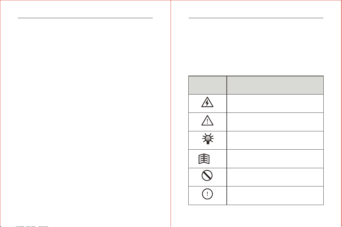
Table of Contennts
Table of Contents
Chapter 5 Operation of the Inverter ............................P32
5.1 Trial Operation ........................................................ P32
5.2 Cautions for Operation..............................................P34
Chapter 6 Introduction to Function Parameters.......... P36
6.1 Tables for Function Parameters ............................... P36
6.2 Detailed Instruction of Function Parameters...............P58
Chapter 7 CommonProblems, Anomalies and Troubleshooting. .. P1 13
7.1 Diagnostic Trouble Codes and Troubleshooting........P113
7.2 Anomalies and Solutions..........................................P117
Chapter 8 Inverter Inspection and Maintenance........P119
8.1 Inspection and Maintenance....................................P119
8.2 Replacement of the Inverter Wearing Parts.............. P123
8.3 Storage of the Inverter ........................................... P124
Chapter 9 OutlineDimensions & Mounting Dimensions.... .P1 25
9. 1 Inverter Outline Dimensions & Mounting Dimensions .. .. .. .. P1 25
9. 2 Operator Panel Outline Dimensions& Mounting Dimensions.. .. P1 26
Chapter 10 Quality Warranty..................................... P127
Appendix Optional Parts Choosing............................P128
User's Warranty..........................................................P130
-1--1-
Chapter 1 Safety Instructions
Chapter 1 Safety Instructions
Safety Symbols Symbol Definitions
HAZARD
This symbol indicates hazardous HIGH VOLTAGE.
Any incorrect operation may result inserious damage
to the equipment or death topersonnel.
WARNING
CAUTION
TIP
FORBIDDEN
COMPULSORY
This symbol indicates that any incorrectoperation can
result in damage to the equipmentor minor to moderate
injury to personnel.
This symbol calls your attention tofollow the
instructions while in operation or inuse.
This symbol calls attention to someuseful messages
for the user.
This symbol indicates anything forbidden todo.
This symbol indicates something must do.
1.1 Safety Symbols and Definitions
The safety instructions described in this manual are very important. To avoid
any error that may resul t in damage to equipment, injury to personnel or loss
of property, do read and clearly understand all of the safety symbols, symbol
definitions and be sure to observethe indicated safety instructions below.
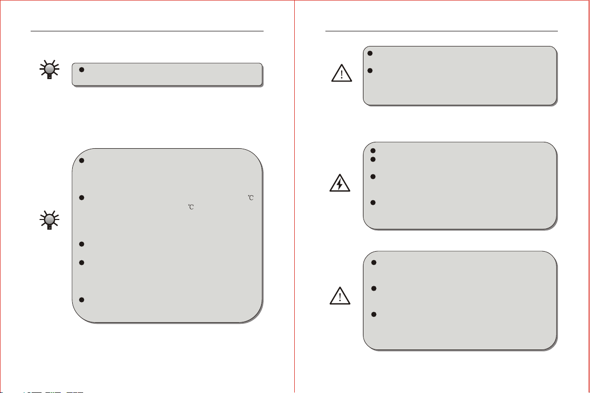
1.2 Application Range
1.3 InstallationAmbient
Chapter 1 Safety Instructions
This inverter isapplicable to general industrial purpose
three-phase ACasynchronic electric motor.
Be sure to install the inverter in a well-ventilated indoor
location. To getthe best cooling effect, it isrecommended
to fix the inverter vertically, and extra ventilation devices
are needed when installed horizontally.
Be sure that the ambient temperature is between -10~40 .
If the temperature is higher than 40 , forced heat radiation
or derating is needed from theexternal. It is recommended
not to usethe inverterin sucha hightemperature. Otherwis e, it
may greatly reducethe servicelifeof the inverter.
The ambient humidity is required to be lower than 90%
without dew condensation.
The inverter shall be installed ina place where thevibration
is less than 0.5G. Otherwise, itmay fall andcause damage
to the equipment. It is also noted worthy that the inverter could
not bear any sudden bump.
The inverter should be kept away from electromagneti c
interference (EMI), flammable and explosive ambient.
CAUTION
CAUTION
-2--2-
1.4 Cautions forInstalling
Chapter 1 Safety Instructions
Be sure toinstall the inverter on metallic materials (i.e.,
Metal). Otherwise, thereis in thedanger of fire.
Be sure not to let the foreignmatter enter into the inverter,
such as wire clippings,spatter fromwelding, metal (zinc or
ferrous) meshavings and etc. Otherwise,there is thedanger
of gettingburned due toshort circuit.
Do not operateelectrical equipment withwet hands.
Do not operate wiringunless the powersupply is completely
off.
Do not open the front cover or perform wiring while
the inverter ispowered ON. Otherwise,there is the danger
of electric shock.
Do wait at least5 minutes afterthe power isdisconnected
before performing thework of wiringor inspection. Otherwise,
there is thedanger of electricshock.
Do not installor operate ifthe inverter isdamaged or has
parts missing to prevent injury to personnel or loss of
property.
The main loop terminal should betightly connected to the
cable. Otherwise, theinverter may bedamaged due toloose
contact.
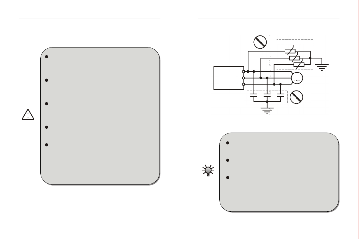
The ground term inal must be reliably andproperly grounded
to ensure security. Toavoid common ground impedance,
multi-piece inverters should be groundedwith one shared
point, as shownin the Figure1-1.
WARNING
HAZARD
WARNING
-3--3-

Inverter Inverter Inverter
Proper
grounding
method
Grounding bus bar
(Connect to the ground at theshared point)
Three-phase
AC
Power Supply
FORBIDDEN
Figure 1-2
Figure 1-1
Chapter 1 Safety Instructions
DO NOT connect control terminals (except terminals mar ked
"TA","TB" and "TC") to AC 220V power supply, which
may cause damage to the inverter.
DO NOT connect AC power supply to the outputterminals
marked "U", "V" and "W". Otherwise, it may cause damage
to the inverter, as shownin the Figure 1-2.
DO install a no-fuse circuit breakeror leakage protective
circuit breaker in the side ofinverter input power supply
to prevent expanding of accident due to an inverterproblem.
FORBIDDEN
COMPULSORY
-4--4-
INVERTER
1.5 Cautions forOperation
Chapter 1 Safety Instructions
It is not suitable to install an electromagnetic contactorin the
side of output power supply, because the operation of open
and close tothe contactor when the motor is running may
cause damage to the inverter arising from over-voltage
produced during this process. But itis still necessary to install
a contactor if one of thefollowing three points occurs:
1. The system of frequency converting governor used to control
energy-saving usually works at a rated rotation speed.To run the
governor economically, thereis a must toremove the inverter.
2. The inverter participates in some import procedure and cannot
stop operating for a long period of time.To realize free shift
in various control systems and improvethe reliability of these
systems, there is a must toinstall a contactor.
3. When an inverter controls severalmotors, there is amust to
install a contactor.
Caution: DO NOT operate the contactorif there is output of the
inverter.
Do not operate electrical equipment withwet hands.
An inverter stored formore than half a year shouldbe given
power up test before use so thatthe main circuit filter capacitor
couldbe recovered. When the inverter is in the stateof powerup,
it is necessary to raise the voltage gradually tothe ratedvalue
with a voltage regulator. Generally, the charging time should
be controlled within 2 hours. Otherwise, thereis the danger
of electric shock or exposure.
Do not touch the inner sideof the inverter while the po wer
is ON, nor put any foreign matter, i.e., rod or other matter
inside the inverter.Otherwise, it may resultin serious damage
to the equipment or electric shock.
Do not open the front cover while the inverter is powered
ON. Otherwise, there is the dangerof electric shock.
Be careful to select the Restart Mode. Otherwise, there is
the danger of personnel death.
CAUTION
-5--5-
HAZARD
R
S
T
U
V
W
GGG
Forbidden
Forbidden
Inverter
Power factor
compensation
capacitor
Surge current sink
Figure 1-3
Chapter 1 Safety Instructions
When the inverter runs at a frequencyhigher than 50Hz, Make
sure it iswithin the speed range acceptable by your motor
bearing and mechanical device.Otherwise,there is the danger
of damage to the motor.
It is not advisory to run thereduction box, gear and other
mechanism that need lubricating at lowspeed for a longperiod.
Otherwise, it may reduce the servicelife ofthese equipment
or even damage the equipment.
Ageneral motor should be derated before use due to less
effective of heat dissipation when itruns at a low frequency.
If it is a constant torque load, then a forced method or a special
variable frequency motor should be usedto release heat.
DO cut off the power supply ofan inverter set aside fora long
time to avoid foreign matter orother things enterin it which
may cause damage to the inverteror even lead to fire.
The output voltage of inverter is PWM impulse wave. DO
NOT install a capacitor or surge current sink(i.e., a varistor)
in the inverter output port. Otherwise,there isthe danger of
fault tripping of the inverter or damage to itspower elements.
DO remove such kind of thingsif already installed. See the
Figure 1-3 below.
WARNING
-6--6-
Chapter 1 Safety Instructions
Motor insulation should be checked before the inverter is
used for the first use or reused after along-term idle. Be sure
the insulation resistance measured is nolower than 5M?
If the inverter is used beyond the range of allowableworking
voltage, then an extra step-up orstep-down voltage transformer
shall be configured.
Due to thin air in a place where the altitude ishigher than
1,000m , the heat dissipation of inverter willbe less effective.
Hence derating should be done before use.In general, when
the height rises by 1,000m, therated voltage of theinverter
shall reduce by 10%.
CAUTION
-7--7-
U
V
W
M

Inverter Model
Design Number
Serial Type Code
Vector Type V
Type Code
Mini Type M
ZVF9V-M0015T4MDR
Name
Inverter Model
Adaptive Motor Power
Input Power Rating
Output Power Rating
Product Number
Chapter 2 Introduction to the Product
2.1 Unpacking and Inspection uponArrival
This product is guaranteed a high level of quality with strict outgoing
inspection,crushproof and shockproof packaging.But this does not preclude
damage tothe product due to heavy collision or strongextrusion.So it
is necessary to u npack the inverter upon arrival and perform these steps:
Check w hethe r there is a defor med or damag ed casing;or any shattered
component.
Check the specifications label of theinverter and make sureitmatches
the product part number you've ordered.
Check whether the items inthe packing list are in readiness or not.
If there is any problem with the above-mentioned contents,please
contact the supplier or Our Companyimmediately.
Chapter 2 Introduction to the Product
2.2 Demonstration of the Model
Motor Power Code
1.5KW 0015
"DR"indicates there is a
braking unit inside.No
"DR",no braking unit
inside.
M:Integration Module
S:Schism Module
VoltageClass Code
220V 2
380V 4
Voltage Phase Number Code
Single Phase S
Three Phase T
Figure 2-1 InverterModel Demonstration
-8--8-
2.3 Specifications Label
Figure 2-2 Inverter Specifications Label
Table 2-1 InverterModels and Specifications
2.4 Models andSpecifications
Inverter Models
M:Mini type
Input
Voltage
V
Rated
Output Current
A
Adaptive
Motor
Power(KW)
ZVF9V-M0007T2/S
ZVF9V-M0015T2/S
ZVF9V-M0022T2/S
ZVF9V-M0007T4
ZVF9V-M0015T4
ZVF9V-M0022T4
220
220
220
380
380
380
4.0
7.5
10.0
2.3
3.7
5.0
0.75
1.5
2.2
0.75
1.5
2.2
-9--9-
Chapter 2 Introduction to the Product

Item Item Description
150% 1 minute; 180% 1 second;200% transient protection
Optimal space voltage vector PWM modulation
Speed sensorless vector control(SVC)
digital setting:Max.frequency 0.01%
Analog setting:Max.Frequency 0.2%
Overload capacity
Modulation method
Control method
Frequency accuracy
Control function
Digital setting:0.01Hz
Analog setting:Max.Frequency 0.1%
Frequency
resolution
0.00 10.00Hz
Starting frequency
Automatic torque lifting:Tolift the torque a
utomatically according to the output current.
Hand-operated torque lifting:Range:0.1 30.0%
Torque lifting
Setting range:0 150%.The inverter output
frequency can be auto-regulated within thisrange
acdording to the motor load soas to reducethe speed
variation of the motor due toload fluctuation.
Slip compensation
0.1 3600.0 sec/min,which can be set insequence.
Acceleration/
deceleration time
1.0 15.0 KHz
Carrier frequency
Jog frequency range:0.01 400.0Hz Jog
acceleration/deceleration time, 0.1~3600.0 can be set.
Jog function
1.linear curve; 2.quadratic curve(conic);
3.User defined V/F curve
V/F curve
Three-phase 0 input voltage VAC
0.00 400.00Hz
Rated voltage
Frequency
Ouput
Rated voltage,frequency Single/three-phase 220VAC,three-phase 380VAC,50Hz/60Hz
Input
Allowable voltage
range
Voltagefluctuation range:-20% +20%
Voltage unbalance rate 3%; frequency fluctuation 5%
Auto optimize V/F curve according toload
fluctuation to realize energy-saving operation.
Automatic
energy-saving
operation
Control function
-10--10-
Chapter 2 Introduction to the Product
Item Item Description
When the network voltage changes,it canregulate
PWM output automatically to maintain constant
voltage.
Auto voltage
regulation(AVR)
This can form a convenient closed-loopcontrol
system(CLCS),and is applicable to pressure control,
flow control and other process control.
Built-in PID
Control function
operator panel control,external terminal control
and COM control
Operating command
Panel potentiometer setting,operator panel
setting,external terminal up/down setting,analog
voltage signal or external potentiometer setting,
analog current signal setting,analog assembly
setting,485 COM setting and etc.
DC braking
Forward/Reverse signal,multiple speed signal,
failure signal,reset signal and etc.
Input Signal
Programmable relay,open-collector output,failure
signal output and etc.
Output signal
This can realize the output offrequency,current and
other physical quantity by outputting 0 10V or
0 20mA DC signal and0 10KHz digital signal.
Multi-function
analog and digital
ouput terminal
Operating function
With an external braking resistor,the maximum
braking torque may reach 100%.
Dynamic braking
This can be selected when themotor starts or stops
with the action frequency of 0 20Hz,action current
level of 0 100% and actuation time of 0 30 sec.,
which can be set in sequence.
DC braking
Braking function
-11--11-
Chapter 2 Introduction to the Product
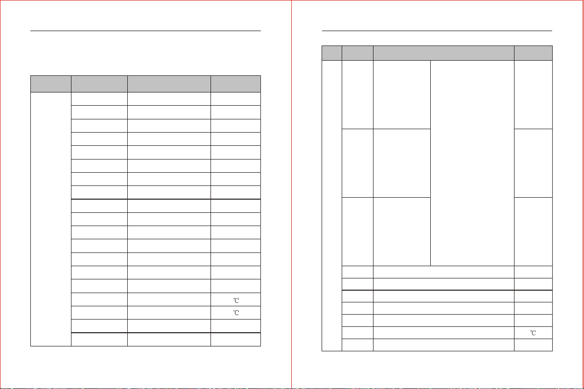
2.5 Technical Indications
Table 2-2 DscriptionSummary for Technical Indications
Item Item Description
Input open-phase protection,over-current protection,
overload protection,under voltage protection,
overheating protection and etc.
Protection function
Real-time display the running state,monitoring
parameters,function parameters,diagnostic trouble
codes(DTC)and other information of the inverter.
LED,LCD display
Brake assembly,remote operator panel,connecting
wire,communication panel
Matching parts
Indoor location free from direct exposureto sunlight,
high humidity or dew condensation,high levelsof
dust,corrosive gas,explosive gas,inflammable gas,
oil mist,salt and etc.
Place to be used
Below 1,000M
Altitude
Ambient
-10 +40 [Bare Machine:-10 +50 ]
Ambient Temperature
20 90%RH without dew condensation
Humidity
0.5G
Vibration
-20 +60
Storage Temperature
Ip20
Forced air cooling
wall mounted
Protective Class
Cooling system
Installation
Structure
-12--12-
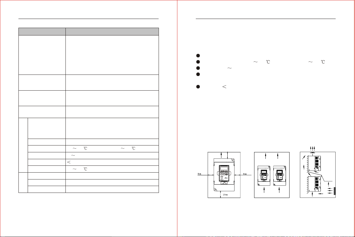
Chapter 2 Introduction to the Product
Air outlet >10cm
>>
>
Air outlet Air outlet
Air inlet
Air inlet
Inverter Inverter
Induced
spacer
Chapter 3 Inverter Installation and Wiring
3.1 Installation
3.1.1 Use the inverter in the following environmental conditions:
Altitude:Maximum 1000m above sea level
Ambient Temperature:-10 +40 [Bare Machine:-10 +50 ]
Humidity:20 90%RH(Non-condensing)
Ambient:Indoor places free from direct exposure to sunlight,dust,
corrosive gas,flammable gas,oil mist,steam,drip and salt.
Vibration: 0.5G
3.1.2 Installation Space and Direction
To get bettercooling effect and for the convenience ofmaintenance,the
inverter shall be installed vertically with enough space left(refer to the
figure 3-1).When two or more invertersare fixed in the same cabinet,it
is recommended to fix them inparallel and horizeontally to reduce heat
produced by them(refer to thefigure 3-2).When there is a mustto fixthem
vertically,please fix aninsulating board between t hem so that the heat
produced by the lower one couldnot have direct influence on the upper
one(refer to the figure 3-3).
Chapter 3 Inverter Installation and Wiring
Figure 3-1 Demonstration
of Installation Space
Figure 3-2 Demonstration
of Multi-piece Parallel
Installation
Figure 3-3 Demonstration
of Multi-piece Vertical
Installation
-13--13-
Other functions
Leap frequency, Jog function,counter, trace to
rotating speed, instant shutdown restarting,
Frequecny upper/lower limitation , acceleration/
deceleration mode regulating, frequency meter and
voltmeter output, multiple speed/program operation,
two-wire/three wire control,vibration frequency
control, Multi-function input terminal selection,
Failure auto reset and 485COM.
Chapter 3 Inverter Installation and Wiring
3.1.3 Installation Instructions
Do not install oroperate if the inverter is damaged or has
parts missing to prevent injury from personnel or loss of
property.
Be sure the main loop terminals should be tightly connected
to the cable. Otherwise, the inverter may be damaged arising
from loose connection.
Be sure that the ground terminals of the inverter and the
motor must be properly grounded. Multi-piece inverter
should be grounded at one sharedpoint.
Be sure to install a no-fuse circuit breaker orleakage protective
circuit breaker in th e side of inverterinput power supply to
prevent expanding of accident due toan inverter problem.
Inst all the in verter i n a proper place with moderate temperature.
The higher the ambient temperature is, the shorter the service
life of the inverter is.
Keep any other heat-producing equipment as far away from
the inverter as possible. When installingthe inverter in an
enclosure,maintainthe clearance around the inverter and
verify the temper ature is withinthe allowable range.
WARNING
FORBIDDEN
CAUTION
-14--14-
3.2 InverterWiring
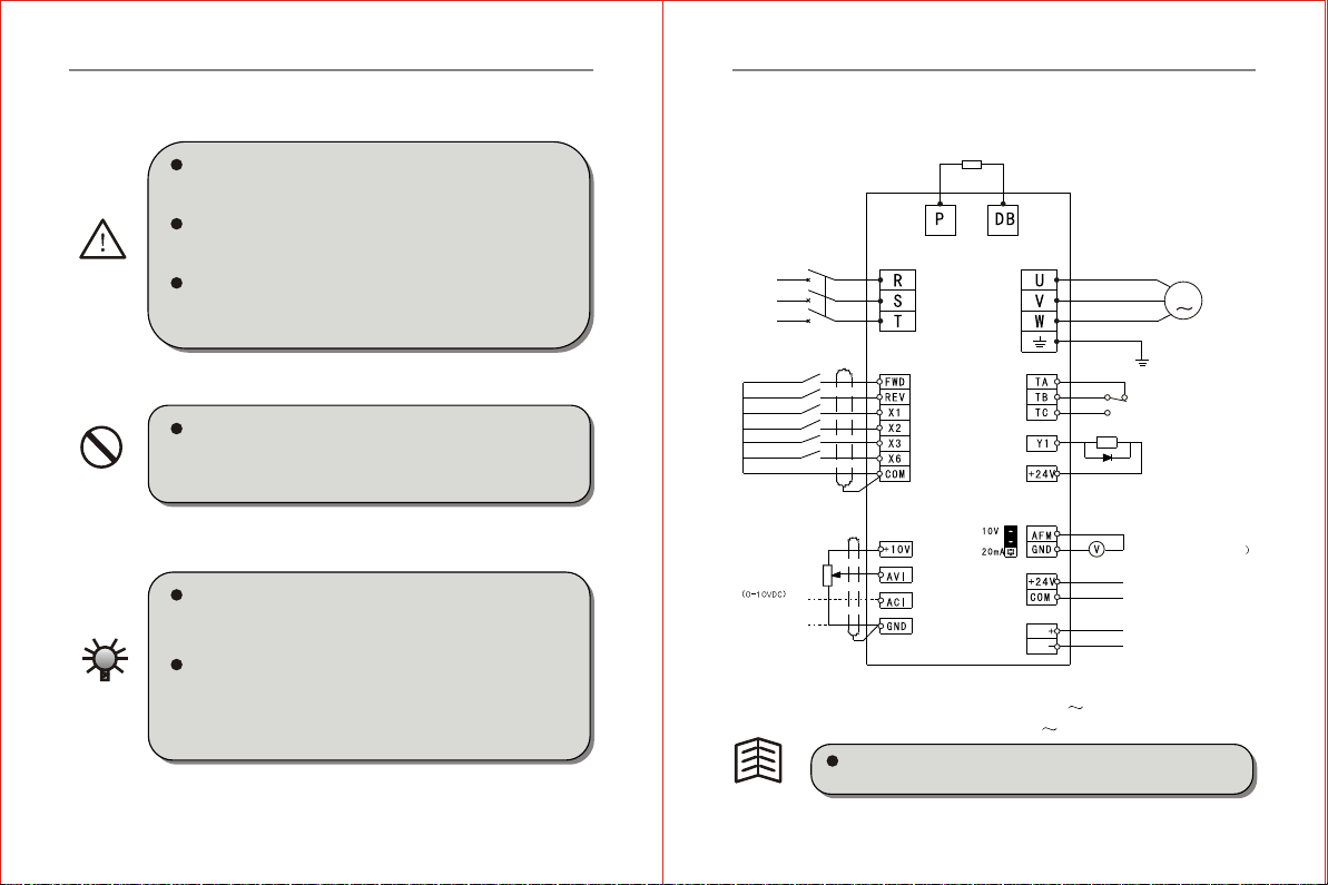
3.2.1 Basic Wiring Diagram for the Inverter
Fig.3-4 Basic Wiring Diagram
Applicable to Model:ZVF9V-M0007T2/S2 M0022T2/S2
ZVF9V-M0007T4 M0022T4
Chapter 3 Inverter Installation and Wiring
-15--15-
Braking Resistor
Three-phase
AC Input
Power Supply
Terminal X1
Terminal X2
Terminal X3
Terminal X6
Public Terminal
Potentiometer
Input or Analog
Voltage Input
Analog
Current Input
(0-20mA)
Fault Relay Output
TA-TB on when normal.
TA-TC on when failure.
Open collector
Output
Analog Signal Output
(0-10VDC or 0-20mA
24 Power Supply
Output Port
485 COM Port
MCCB
SG
SG
M
Forward Running
Reverse Running
JP2 is used to realize switching betweenanalog output voltage
and current.
Tips
3.2.2 Cautions forWiring
Wait atleast 5 minutes after power OFFbefore opening the
front cover of the inverter.
Verifythe charge indicator lamp isOFF before proceedin g
the work, and be sure that the voltage valueof the main loop
terminal P and DC isless than 36VDC.
The internal wiring of the invertershould be operated only
by authorized qualified personnel.
Verify therated input voltage of the inverteris matched with
AC power supply. Otherwise, there is the possibility of
damage to the inverter.
Be sure to installa non-fuse circuit breaker in the input
power supply sideof the inverter to prevent expanding of
accident due to an inverter problem, which may cause
damage to the distribution equipment orlead to fire.
Be sure to connect the ground terminal and the motor casing
to the ground wire which must be copper core. Thediameter
of the copper core should conform to the relevant national
standard. The ground resistance shouldbe less than 10 .
Chapter 3 Inverter Installation and Wiring
HAZARD
WARNING
-16--16-
Chapter 3 Inverter Installation and Wiring
DO NOT connect AC powersupply to the output terminals
marked "U", "V" and "W". Otherwise, therewill be damage
to the inverter.
DO NOT connect control terminals (except terminals marke d
"TA","TB" and "TC") toAC 220V powersupply, which
may cause damage to the inverter.
FORBIDDEN
When the open-ended output terminal of the collector
connects to any inductive load, i.e., the relay coil,do insert
a diode at each end ofthe load in parallel.
The control wire in the inverter or thecontrol cabinet should
be at least 100mm away fromthe power cable. DO NOT put
them in the same metallic channel.If the signal wire and
the power cable need to intersect,they should intersect at
an angle of 90 . The control wire mustadopt STP (shielded
twisted pair wire); the shielded layermust connect to the
terminal GND; and the power wire is recommended touse
metallic shielded cable.
Tips
The unavoidable strong electromagnetic interference of
the inverter mayhave bad influence on all the electrical
equipment and meters in the same environment. To reduce
interference, the outputcable of theinvertercan be inserted
in the metal pipe connecting to the groundor in the metallic
shielded cable, and connect the metallicshielded layer to
the ground. In addition, a magneticloop puton the output
cable is also effective to reduceinterference.
Tips
-17--17-

Chapter 3 Inverter Installation and Wiring
3.2.3 Instruction onMain Circuit Terminals
1. The maincircuit terminals areshown as in the figure 3-5~3-6.
Fig.3-5 Diagram 1for Main Circuit Terminals
Applicable t0 Model
Earthing
Single phase 220V power input
R S T
Connect with
three-phase AC motor
Connect with the
braking resistor
Fig.3-6 Diagram 1for Main Circuit Terminals
Three-phase 220/380V power input
ZVF9V-M0007T2/S2 M0022T2/S2
ZVF9V-M0007T4 M0022T4
-18--18-
Earthing
2 Function Description onMain Circuit Terminals
The three-phase input power supply connect tothe terminals
(R, Sand T) do not differ on phase sequence and can be
conn ect ed arbitrarily.
If the motor counterrotates (reverses) when the output
terminals U, V and Wconnect to three-phase motor, just
exchange two phases of U, Vand W arbitrarily.
Terminal Symbols Function Description
Power supply inputterminals connecting tothree-
phase 380V or220V ACinput
Power supply inputterminals connecting tosingle-
phase 220VAC input
Inverter output terminalsconnecting to three-phase
AC motor
External braking resistorterminals connecting to
both ends ofthe external brakingresistor
RST
LN
UVW
PDB
Chapter 3 Inverter Installation and Wiring
G Ground terminal connecting to the ground
Tips
-19--19-
3.2.4 Description ofterminals on the control circuit
1 The terminal ofcontrol circuit shownin Fig 3-7.
Fig 3-7 Terminals of controlcircuit

Chapter 3 Inverter Installation and Wiring
2 Description on ControlCircuit Terminals
Table 3-2Function Description onControl Circuit Terminals
Types Terminal
Symbols Function Description Electrical Specifications
Public
Port
Digital signal public
terminal
Forward when FWD-COM
short circuit, decelerate and
stop when FWD-COM is open.
Running Control
Terminal
Reverse when FWD-COM
short c ircuit , decelerate and stop
when FWD-COM is open.
INPUT, 0~24 power level,
low level valid, 5mA
Multi-function
Input Terminal
X1
X2
X3
X6
COM
FW D
REV
Multi-function
Output Terminal
Multi-function open-
collector output is defined as
on-off output terminal, whose
function is set by the
parameter F4.07 with
reference of COM.
Valid onlywhen there is a
short circuit between Xn (n=
1, 2,3, 6)and COM. The
functions can be set by the
parameter F4.00~F4.05
separately.
Y1
INPUT, 0~24 power
level, low level valid,
5mA
OUTPUT, Maximum
Current Load
50mA
Analog signal public
terminal
GND
Public
Port
-20--20-
Types Terminal
Symbols Function Description Electrical Specifications
Chapter 3 Inverter Installation and Wiring
External analog preset
power supply connecting to
potentiometer together with
terminal GND and AVI.The
frequency can be set as
required.
INPUT,10V DC voltage
+10V
AVI
Analog Input
Terminal
Analog voltage signal input,
with reference of GND. INPUT,0 10V DC voltage
Analog current signal input,
with reference of GND
INPUT,0 20mA DC
current
ACI
Programmable analog voltage
ouuput connecting to the
voltmeter of frequency meter
with corresponding output
ranging from "0"to the maximum
frequency,with reference of GND.
AFM
Analog Output
Terminal
OUTPUT,0 10V DC
voltage or 0 20mA
DC current
communication
port
+24V
TA
24VDC-100mA
24VDC Power Supply
Output(Control Power
Supply)
Power
supply
Interface
Relay contact output.When
normal,Ta-TB turns onand
TA-TC turns off.When there
is action,TA-TB turnsoff
and TA-TCturns on.This
function is set by F4.09.
TB
TC
Contact rated value:
250VAC-3A
250VAC-1A
30VDC-1A
Programmable
Output Terminal
Communication Signal
Positive Port
Communication Signal
Negative Port
SG+
SG-
-21--21-
Chapter 3 Inverter Installation and Wiring
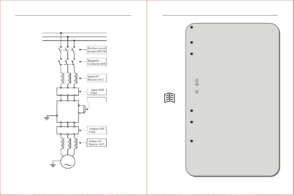
3.3 Wiring Diagram for InverterSystem
Fig.3-8 Connection betweenthe Inverter and Optional Accessories
-22--22-
Exteral Breaking
unit
INVERTER
UVW
G
RST
P
DB
M
The circuit breaker has the function of over-current
protection,which can avoid extension of external
equipment failure. Dopay attention to the capacity of
circuit breaker when installing.
The magnetic contactor is used todisconnect fro m the
main power supply in case ofinverter failure, and prevent
restarting after power-off or inverterfailure.
The input ACreactor can reduce influence arising from
unbalance of three-phaseAC power supply, improve the
power factor of the inverter inputside and reduce damage
to the inverter when it isconnected to large capacity motor
which may result in damage tothe rectifier circuit.It is
necessary to configure an AC reactor when any of the
following occurred:
The power supply unbalance exceeds3%.
The power capacity is 500KVA atleast and it is more
than 10 times as the invertercapacity.
The power factor is used tocompensate the connection
or disconnectio n of the capacity, and sudden fluctuation
of network voltage caused by otherreasons.
It is recommended to install areactor with deratingvoltage
of 3%.
The inputand output EMI filters are used to minimize
the magnetic or radio frequency interference (RFI)
produced by the network or theinverter.
The brake assembly is usedto consume the energy fed
back by some heavy potential energy or inertia load to
the inverter, so as to avoid inverter trippingarising from
over-tension pumping voltage while giving a quick
shutdown to the inverter.
The output AC reactor can filter out with effect the higher
harmonic compon ents in the inverter output currentand
reduce theelectromagnetic interference (EMI) due to
ultraharmonics. Also, it canimprove current waveform,
decrease noise and temperature rise ofa running motor
and enhance the stability of motor running. To avoid
influence of leakage current dueto distributed capacity
of the cable, it is necessaryto install an output AC reactor
if the motor cable is longer.
Chapter 3 Inverter Installation and Wiring
Tips
-23--23-
Chapter 4 Operator panel and its Operation
4.1 Operator Paneland Description
The inverter ZVF9Vseries has 3kinds of operationpanels,The standard
M Type have potentionmeterwhen out of factory.
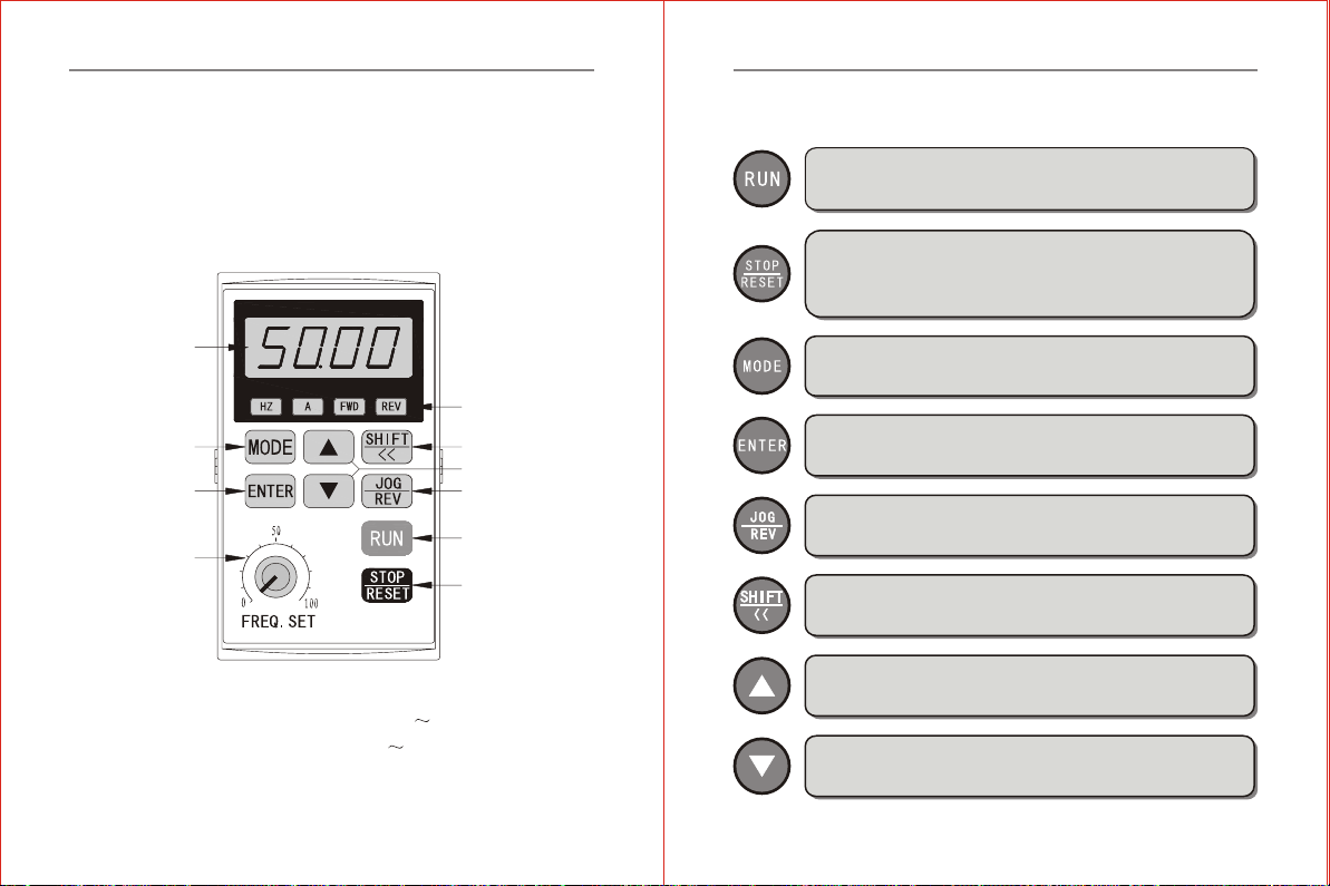
4.1.1 Operator PanelOutlay
Applicable to Model:
LED display area
Display the
running status
ENTER/STORE Key
MODE Key
Potentionmeter Key
SHIFT/MONITOR Key
LED display area,
display frequency,
current, parameters,
error and etc.
UP/DOWN Key
RUN Key
STOP/RESET Key
JOG/REVERSE Key
Chapter 4 Operator panel and its Operation
ZVF9V-M0007T2/S2 M0022T2/S2
ZVF9V-M0007T4 M0022T4
-24--24-
4.1.2 Function Descriptionon Keys
Run key: When the operating instruction is to select operator
panel control (F0.04=0), press this keyand the inverter begins
to run.
Stop/Reset key: When the operating instruction is toselect operator
panel control (F0.04=0), the inverter is in normal running. Press
this key to stop run ning. When the inverter is in the stateof failure
alarming,press thiskey to solve failure and return to the normal
status.
Mode shifting key: Press this key to realize mode switching from
monitoring parameter to function parameter.
Enter/Store key: Press this key to confirm the current status of the
inverter or save the current parametervalue.
Jog/Reverse key: Press this key to realize jogor reservefunction,
and decide jog or reverse functionby selecting the parameter F0.23.
The factory default setting is jogfunction.
Shift/Monitor key: When a data needs modifying, press this key
to select the modifier bit ofthe data. In the status of monitoring,
press this key to display thestatus parameter.
Up key: Press this key, thedata or parameter code will goup. Press
and hold it, the modifying speedupward will rise.
Down key: Press this key, the data or parameter code will go down.
Press and hold it on, themodifying speed downward will rise.
Chapter 4 Operator panel and its Operation
-25--25-
Chapter 4 Operator panel and its Operation
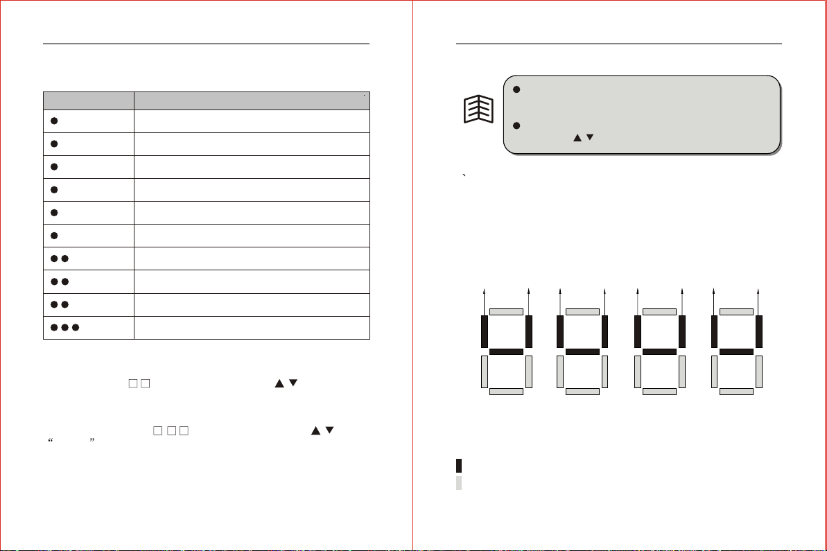
4.1.3 Function Descriptionon Operator Panel Indicator Lights
Table 4-1LED Status Description
Display Status Function Description
When this indicatorlight is switchedON, LED displays
frequency data.
When this indicatorlight is switchedON, LED
displays current data.
When this indicatorlight is switchedON, LED
displays voltage data.
When this indicatorlight is switchedON, the inverter
is in thestate of forwardrunning.
When the indicatorlights is switchedON, the inverter
is in thestate of reverserunning.
When these 2indicator lights areswitched ON
simultaneously, therotary speed willbe displayed.
When these 2indicator lights areswitched ON
simultaneously, thepercentage will bedisplayed.
When these 2indicator lights areswitched ON
simultaneously, thelinear speed willbe displayed.
When these 3indicator lights areswitched ON
simultaneously,temperature willbe displayed.
4.1.4 Working mode anddisplay status ofthe function keyboard
1. Mode ofMonitoring State
Press "M ODE" key, the inverter ente rs into the monitoringstate mode
(LED displays Fd ). Under thismode, press / to decide what
to be monitored(i.e., a running parameter or failurerecord).
2. Mode ofFunction Status
Repress "MODE" key, the inverter will enter the mode of function
status (LED displaysF . ). Underthis mode, press / or plus
SHIFT key to decidethe function parameter to be checked or
modified.
3. Power On/OffDisplay
The LED displaysP.oFFwhen the inverter startenergize orpowered off
properly.
Hz
A
V
ALM
FWD
REV
Hz&A
Hz&V
A&V
Hz&A&V
-26--26-
In any event, the operator panelwill automatically return to
the Monitoring Mode if there is no key entry in 2 continuous
minutes.
In the mode of monitoring, the frequencyvalue will be modified
by pressing / on the operator panel when setting F0.01=1.
4 The correspondence between display symbols ofthe parameter
Fd14 and external inputterminal status in themonitoringmode
is shown below:
Terminal
Status
Terminal
Status
Terminal
Status
Terminal
Status
Terminal
Status
Terminal
Status
Terminal
Status
Terminal
Status
Fig. 4-3 Relationshipbetween input terminal
status and displaysymbols in monitoring mode
: Terminal turns ON,valid input of terminal
: Terminal turns OFF, invalid input of terminal
FWD REV X5 X6 X3 X4 X1 X2
Tips
Chapter 4 Operator panel and its Operation
-27--27-

4.1.5 Use ofOperator Panel
Parameter modification inthe monitoring status(modify the motor
rotating speed fromFd00 to Fd04).
Initializing
Modification of parametervalue for function codes (modify the
parame ter value for F2.19jog function from10.00Hz to 20.00Hz).
Initializing
Chapter 4 Operator panel and its Operation
-28--28-
Initializing
Modification of parametervalue for function codes (modify the
parameter value forF0.01 frequency setting mode from 1to 0)
Parameter initializing (restoreto the factory default setting)
indicates the digital
tube is flickering;
indicates the digital
tube is notflickering.
Initializing
Tips
Chapter 4 Operator panel and its Operation
-29--29-
Chapter 4 Operator panel and its Operation
Table 4-2Monitoring Parameter LEDDisplay List
4.2 Monitoring ParameterDisplay
Category Display Code Name Unit
Monitoring Display Parameters
Output frequency
Setting frequency
Output current
Output voltage
Motor rotation speed
Running linear speed
Setting linear speed
DC bus barvoltage
Input voltage
PID set value
PID feedback value
Analog inputAVI
Analog inputACI
Impulse input frequency
Input terminal status
Radiator temperature
Module temperature
Current counter value
Setting counter value
Hz
Hz
A
V
r/min
m/s
m/s
V
V
V
mA
KHz
Fd00
Fd01
Fd02
Fd03
Fd04
Fd05
Fd06
Fd07
Fd08
Fd09
Fd10
Fd11
Fd12
Fd13
Fd14
Fd15
Fd16
Fd17
Fd18
-30--30-
Monitoring Display Parameters
1st diagnostic
failure codes
2nd diagnostic
failure codes
3rd diagnostic
failure codes
0:OC-1 Acceleration
running over current
1:OC-2 Deceleration
running over current
2:OC-3 Steady-speed
running over current
3:OU-1 Acceleration
running over voltage
4:OU-2 Deceleration
running over voltage
5:OU-3 Steady running
over voltage
6:OU-4 Over voltage when
power off
7:LU Under voltage of running
8:LP Input side open-phase
9:SC Power module failure
10:OH Radiator over heat
11:OL Inverter overload
12:OL Motor overload
13:EF external equipment
failure
14:CE-1 COM error
15:CE-2 Remain
16:CE-3 Current detection error
17:CE-4 Keyboard
communication failure
18:CPU failure
Output frequency of the last failure
Setting frequency of the last failure
Output current of the last failure
Output voltage of the last failure
DC bus bar voltage of thelast failure
Module temperature of the last failure
Software version
Category
Display Code
Name Unit
Fd19
Fd20
Fd21
Fd22
Fd23
Fd24
Fd25
Fd26
Fd27
Fd28
Hz
Hz
A
V
V
Chapter 4 Operator panel and its Operation
-31--31-

-32--32-
Chapter 5 Operation of Inverter
5.1 TrialOperation
5.1.1 Safety Instructionon Trial Operation
The following stepsshould be inspectedand confirmed beforethe trial
operation of theinverter:
Be sure the application ambien t and installationfor the inverter is
in accordance withthe requirements specified in Clause 3.1.
Be sure themain circuit iscorrectly wired. Theinput power supply
of theinvertermust beconnected to the terminalR, S and T(orL,
N. The output terminal U, Vand W must be connectedto the motor.
Be sure theground terminal is reliably and properlygrounded.
Be sure allthe switches and terminals are inproper state ofoff or
shut down.
Be sure there isno short cuttingor short toground of allthe terminals
and electrified parts.
Be sure allthe terminals, connectorsand screws are tightly fastened .
Be sure themotor has no other loads.
5.1.2 TrialOperation
Try thisstep only aftercareful inspection asmentioned in theclause
5.1.1.While in trialoperation, it issuggested that the motor hasvacant
load to avoid damage to this mechanicalequipment arising fromincorrect
operation. During trial operation, if theoperating instruction isF0.04,
then the RUN/STOP key control (factory default setting) ofthe operator
panel must beselected. The trialoperationstepsmust befollowed as
shown in thetable 5-1 below.
Chapter 5 Operation of Inverter
Table 5-1Trial OperationSteps
Order Operation Description
Switch on, inverter
energized.
When energized, the inverter isin the
state of readiness and LED displays
0.00Hz.
Press / till LED
displays 5.00Hz.
Set the frequency to 5.00Hz. Thisstep
can be left out if thedisplayed frequency
is already 5.00Hz when energized.
Press RUN .
Motor begins rotating, the frequency displayed
on the inverter LED raises from 0.00Hz to 5.00Hz,
and the built-in cooling fan begins working.
Keep a close eye on the
following points:
if there is any abnormal
vibration or noise when the
motor runs.
if there is any tripping or
other abnormality of the
inverter.
If the motor runs in the
correct direction.
if the value for rotation
speed and frequency is
correct.
If there is any anomaly ortripping, stop
running immediately and cut offthe
power supply. Please referto Chapter 7,
find the trouble causes, then proceedtrial
operation again after troubleshooting.
If the motor runs in thewrong direction,
change arbitrary two-phase connection
of the output terminal U,V or W.
Go to the next step ifeverything is
normal.
Press continuously till
LED displays 50.00Hz.
The motor accelerates rotating and the displayed
frequency rises from 5.00Hz to 50.00Hz. Go to
the next step if everything is normal.
Press continuously till
LED displays 0.00Hz.
The motor decelerates rotating and the displayed
frequency falls from 50.00Hz to 0.00 Hz. Go to
the next step if everything is normal.
Press STOP .
The inverter stops outputting, the motor stops running
and the trial operation ends. If everything is normal,
please repeat the operation for several times.
2
3
4
5
6
7
Chapter 5 Operation of Inverter
-33--33-
-34--34-
All the inverter functions are determinedby set parameters.The
parametersof inverter ZVF9V-M series consist of thefunction codes
F0.00~FA.12, seethe detail inChapter6 ofthis manual.The displayed
parameter value ofeach function code is the factory defaultvalue of
the inverter beforeEX factory,which can bemodified by the user
accordingto hisneeds. It isnoteworthy that a user shall change the
relative function parameterswhen he amends a parameter because
some of theparameters are inter-related.It is not recommended to
modify the setparameter value if there is nospecial requirement, for
the factory defaultsetting has beendone properly.Otherwise,thismay
cause damage tothe inverter orequipment due to error parameter.
In case thereis an error alternation ofthe parameter, please initialize
the parameter withreference to theoperation method in the clause
4.1.5 Parameter Initializing Restoring Factory DefaultSettings .
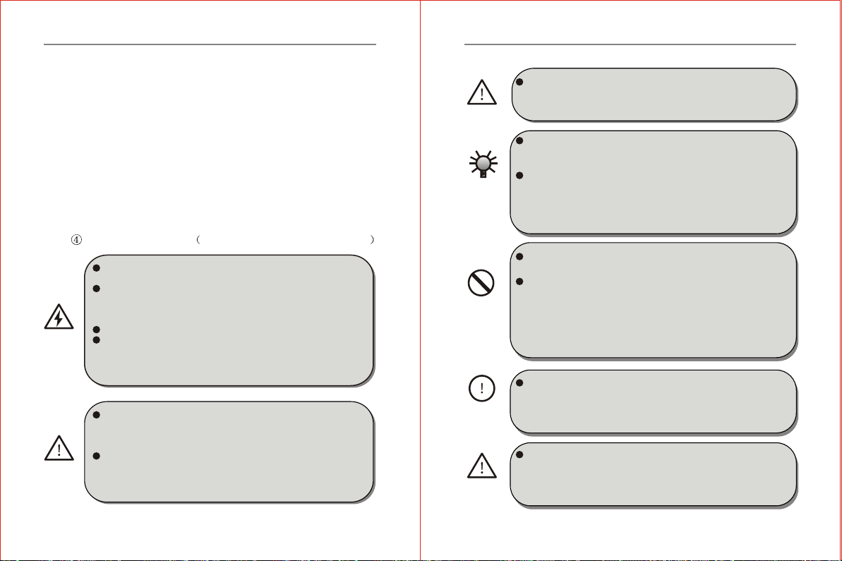
Do not open thefront cover whilethe inverter is powered ON.
Otherwise, there isthe danger of electric shock.
Do not touchthe inner sideof the inverter while the power is
ON, nor put any foreign matter, i.e., rodor other matterinside
the inverte r. Otherwise, itmay result inserious damage tothe
equipment or death to personnel.
Do not operatethe inverter withwet hands.
If Retry Modeis set, please put a warning sign like "KEEP
CLEAR" or "HAZARD"in an eye-catching place before the
equipment to avoid suddenrestartof theequipment aftera trip
stop that may result in injury to personnel.
5.2 Cautions forOperation
If the inverter runsat a frequencyhigher than 50Hz, DOconfirm
it is within the speed range acceptable by yourmotor bearing
and mechanical device. Otherwise, there is the danger of
damage to themotor.
Derating should be donebefore use dueto less effective of heat
dissipation when ageneral motor runs at a low frequency. If
it is aconstant torque load, then a forced method ora special
variable frequency motorshould be used to release heat.
HAZARD
WARNING
Chapter 5 Operation of Inverter
DO cut offthe power supply of an inverterset aside for a long
time toavoid foreign matter or other things enter in itwhich
may cause damage to the inverter or even lead to fire.
If the inverter is used beyondthe range of allowable working
voltage, then an extra step-up orstep-down voltage transformer
shall be configured.
Due to thin air in a placewhere the altitude is higher than 1,000m,
heat dissipation of the inverter will be less effective. Hence
derating should be performed before use. In general, when t he
height rises by 1,000m, the rated voltage of theinverter shall be
reduced by 10%.
DO NOT touch the radiator or charging resistor of the inverter
with hand(s). Otherwise, there is the possibility of getting scalded.
DO NOTproceed direct start-stop operation frequently with a
contactor or any other switch devices in the inverter input side.
As large charging current exists inthe main circuit of the inverter,
frequent power-on/off may produce cumulativeeffect resulting
in heat fatigue ofinverter components and great reduction of
service life of the inverter.
In case abnormalities occur,such as smoke, off odor, strange
sound and so on, DO cut offthe power supply immediately,
overhaul the equipment or turn to the agent for help via phone
call.
The contactor KM1 and KM2 mustbe designed in interlocked
manner to realize converting between power frequency and
variable frequency.It is forbiddento close synchronously.
Otherwise,it may lead to permanent damage to the inverter.
WARNING
CAUTION
FORBIDDEN
COMPULSORY
WARNING
Chapter 5 Operation of Inverter
-35--35-
This manual suits for next models
6
Table of contents
Other Chziri Inverter manuals


Popular Inverter manuals by other brands


BARRON
BARRON EXITRONIX Tucson Micro Series installation instructions

Baumer
Baumer HUBNER TDP 0,2 Series Mounting and operating instructions

electroil
electroil ITTPD11W-RS-BC Operation and Maintenance Handbook

Silicon Solar
Silicon Solar TPS555-1230 instruction manual

Mission Critical
Mission Critical Xantrex Freedom SW-RVC owner's guide

HP
HP 3312A Operating and service manual


