Chziri ZVF200-M User manual

User's Manual
ZVF200-M Vector Inverter
User's Manual
ZVF200-M Vector Inverter
Manufacturer: Wenzhou Ziri Electrical Technology Co.,Ltd.
Add: NO.66 , Daqiao Road , Liushi Town ,Yueqing City , 325604. Zhejiang ,China .
Tel: +86-577-27863300
Http://www.chziri.com
Manufacturer: Wenzhou Ziri Electrical Technology Co.,Ltd.
Add: NO.66 , Daqiao Road , Liushi Town ,Yueqing City , 325604. Zhejiang ,China .
Tel: +86-577-27863300
Http://www.chziri.com

Thank you verymuch for yourpurchase of theinverter
ZVF200-M series.
This manual introduces the installation, operation,
function setting, troubleshooting and etc.of the inverter
ZVF200-M series..
Incorrect installation or use may result in damage or
other accidents. Doread all instructionsin detail be
fore installing or operating.
Please forward thismanual to the end user, and keep
it handy for quick reference.If there areany doubts
or questions, please contact the Technical Service
Center of Our Company
Foreword Table of Contents
Chapter 1 Safety Instruction..................................................P1
1.1 Safety Symbolsand Definition ............................................P1
1.2 Application Range .............................................................P2
1.3 Installation Ambient ..........................................................P2
1.4 Cautions for Installing........................................................P3
1.5 Cautions for Operation .......................................................P5
1.6 Cautions for Disposing .......................................................P8
Chapter 2 Introduction to the Product....................................P9
2.1 Inspection upon Arrival ........................................................P9
2.2 Demonstration ofthe Model ................................................P9
2.3 Specification Label ..........................................................P10
2.4 Outside Drawing& Structure.............................................P10
2.5 Models and Specifications ................................................P11
2.6 Technical Indication .........................................................P12
Chapter 3 Installation and Wiring ......................................P15
3.1 Installation ......................................................................P15
3.2 Remote control keypads and wiring connection ..................P16
3.3 Wiring Diagram ...............................................................P18
3.4 Inverter SystemWiring .....................................................P25
Chapter 4 Operationpanel and Operation ...........................P26
4.1 Operation Panel and Description ..................................... .P26
Tableof Contents
-1-
1.1 Safety Symbols and Definition
The safety instructions described in this manual arevery important. Toavoid
any error that may resul t indamage to equipment, injury to personnel orloss
of property, do readand clearly understand all of the safety symbols, symbol
definitions and be sure to observe the indicatedsafety instructions below.
Chapter 1 Safety Instruction
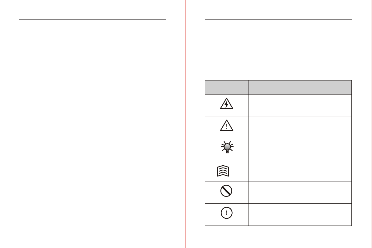
Safety Symbols
HAZARD
WARNING
CAUTION
TIP
Symbol Definitions
This symbol indicates hazardous HIGH VOLTAGE.
Any incorrect operation may result in serious damage
to the equipment or death to personnel.
This symbol indicates that any incorrect operation can
result in damage to the equipment or minor to moderate
injury to personnel.
This symbol calls your attention to follow the instructions
while in operation or in use.
This symbol calls attention to some useful messages
for the user.
FORBIDDEN
COMPULSORY
This symbol indicates anything forbidden to do.
This symbol indicates something must do.
Chapter 1 Safety Instruction
Tableof Contents
Chapter 5 InverterUse ............................................................P31
5.1 Trial Operation ...................................................................P31
5.2 Examples of Use..................................................................P34
Chapter 6 Parameters ............................................................P40
6.1 Schedule of Function Parameters ........................................P40
6.2 Description of Parameters Settings ......................................P60
Chapter 7 Common Fault & Anomalies and Solutions............P120
7.1 Fault Code Information.....................................................P120
7.2 Anomalies and Solutions...................................................P124
Chapter 8 Inverter Inspection and Maintenance..................P126
8.1 Inspection and Maintenance...............................................P126
8.2 Replacement of the Inverter Wearing Parts......................... P130
8.3 Storage of the Inverter .......................................................P131
Chapter 9 Outline & Mounting Dimension............................P132
9.1 Inverter Outline Dimensions& Mounting Dimensions ........P132
9.2 Operation Panel Outline Dimension and Mounting Hole
Dimension ........................................................................P134
Chapter 10 Quality Warranty...............................................P135
Appendix..............................................................................P136
Appendix 1 Optional Parts Selection........................................P136
Appendix 2 EMI Protection.....................................................P138
Appendix 3 RS485 communication protocol.............................P145
Appendix 4 Inverter User's Warranty Bill.................................P159

-2- -3-
Chapter 1 Safety InstructionChapter 1 Safety Instruction
CAUTION
WARNING
1.3 Installation Ambient
1.2 Application Range
1.4 Cautions for Installing
CAUTION
This inverter is applicable to generalindustrial purpose
threephase AC asynchronic electricmotor.
This inverter can not be used in the equipment that may result
in threat or injury to personnel due to inverter trouble orerror,
such as nuclear power control equipment, aviation equipment,
transportation equipment, life supporting system, safety
equipment, weapon system and etc. Please consult Ziri Company
before using it for special purposes.
This product is made under st rict quality control and supervision.
But when used in some key equipment, protective measures
should be taken to avoid further extension of accident due to
inverter trouble.
Be sure to install the inver ter in a well-ventilated indoor location.
To get the best cooling effect, it is recommended tofix the inverter
vertically, and extra ventilation devices are neededwhen installed
horizontally.
Be sure that the ambient temperatureis between -10~45 .If the
temperature is higher than 40 , please removethe upper cover. If
the temperature is higher than 50 , forced heat radiation orderating
is needed from the external. It is recommended not to use the
inverter in suc h a high temperature. Otherwise, it may greatly
reduce the service life of the inverter.
The ambient humidity is required to be lower than 90% without
dew condensation.
The inverter shall be installed in a place where the vibration is
less than 0.5G. Otherwise, it may fall and cause damage to the
equipment. It is also noteworthy that theinverter could not bear
any sudden bump.
The inverter should be kept away from electromagneticinterference
(EMI), flammable and explosive ambient.
WARNING
Be sure to install the inverter onmetallic materials (i.e., metal).
Otherwise, there is the danger of fire.
Be sure not to let the foreignmatter enter into the inverter, such as
wireclippings, spatter from welding, metal (zinc or ferrous)
meshavings and etc.Otherwise, there is the danger of getting
burned due to short circuit.
HAZARD
Do not operate electrical equipment withwet hands.
Do not operate wiring unless thepower supply is com pletely
off.
Do not open the front cover or perform wiring while the inverter
is powered ON. Otherwise, there is thedanger ofelectric shock.
Do wait at least 10minutes after the power is disconnected
before performing the work of wiring orinspection. Otherwise,
there is the danger of electric shock.
WARNING
Do not install or operate if theinverter is damaged or has parts
missing to prevent injury to personnel orloss of property.
The main loop terminal should be tightly connected to the cable.
Otherwise, the inverter may be damaged dueto loose contact.
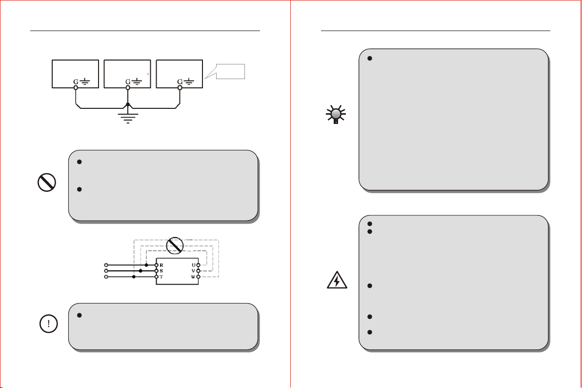
The ground terminal must be reliablyand properly grounded to
ensure security.To avoid commonground impedance, multipiece
inverters should be grounded at one shared point, as shown in
the Figure 1-1.
FORBIDDEN
COMPULSORY
CAUTION
Inverter Inverter Inverter Proper
grounding
method
Grounding with bus bar
(Connect to the groundat the same point)
Three-phase
AC
Power Supply
FORBIDDEN
Figure 1-2
Figure 1-1
DO NOT connect control terminals (except termina ls marked
"TA", "TB"and "TC") to AC220V power supply, which may
cause damage to the inverter.
DO NOT connect AC power supply to the output terminals
marked "U", "V"and "W". Otherwise, i t may c ause damag e
to the inverter, as shownin theFigure 1-2.
DO install a no-fuse circuit breaker or leakage protective
circuitbreaker in the side of inverter input power supply to
prevent expanding of accident due to aninverter problem.
It is not advisable to install anelectromagnetic contactor in the
side of output power supply, because the operation of open and
close to the contactor when the motor is runn ing may cause
damage to the inverter arisingfrom over-voltageproducedduring
this process. But it is still necessary to install acontactor if ther e
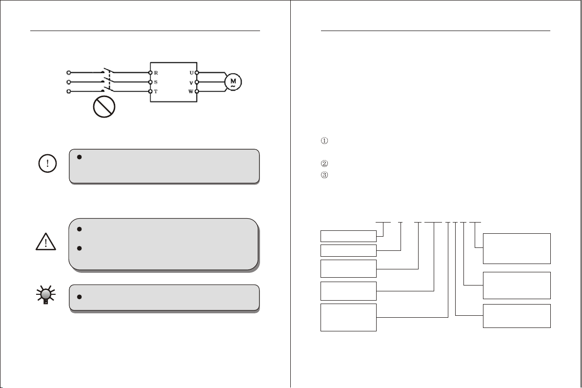
have one situation of the following three points:
1. The system of frequency inverter used to controlenergy saving
usually works at a rated rotation speed. To run the inverter
economically, there is amust to remove the inverter.
2. The inverter participates in some important procedure and cannot
stop operating for a long period oftime. To realizefree shift in
various control systems and improve the reliability of these
systems, there is a must to installa contactor.
3. When an inverter controls severalmotors, there is a must to in
stall a contactor.
Caution: DO NOT operate the contactor if there is output of the
inverter.
1.5 Cautions for Operation
Do not operate electrical equipment withwet hands.
An inverter stored fo r a year or longer should be given powerup
test before use so that the maincircuit filter capacitor could be
recovered.When the inverter is in the state of power up,it is
necessary to raise the voltage gradually tothe rated value wit h
a voltage regulator. Generally, the charging time should be
controlled within 1~2 hours. Otherwise, there is the danger of
electric shock or exposure.
Do not touch the inner sideof the inverter while the power is
ON, or put any foreign matter, i.e., rod orother matter inside
the inverter. Otherwise, it may result in serious damage to the
equipment or death to personnel.
Do not openthe front cover while the inverter is powered ON.
Otherwise, there is the danger of electricshock.
Be careful to select the RestartMode. Otherwise, there is the
danger of personnel death.
-5-
-4-
INVERTER
HAZARD
Chapter 1 Safety InstructionChapter 1 Safety Instruction
FORBIDDEN
Forbidden
Forbidden
Inverter
Power factor
compensation
capacitor
Surge current sink
Figure 1-3
M
Figure 1-4 Diagramof Inverter Derating Curve
WARNING
If the inverter runsat a frequency higher than 50Hz, DO confirm
it is within the speed range acceptable by your motor bearing and
mechanical device. Otherwise, there is the dangerof damage to
the motor.
It is not advisory to run the reduction box, gear and other
mechanism that need lubricating at low speed for a long period.
Otherwise, it may reduce the service life of these equipment or
even damage the equipment.
A general motor should be derated beforeuse dueto lesseffective
of heat dissipation when it runs at a low frequency.If it is a constant
torque load, then a forced method or a special variable frequency
motor should be used to release heat.
DO cut off the power supply of an inverter set aside fora long
time to avoid foreign matter or other things enter in it which may
cause damage to the inverter or evenlead to fire.
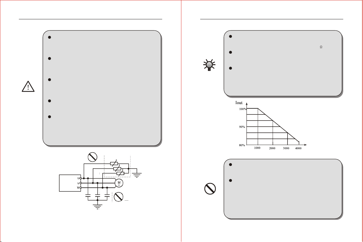
The output voltage of inverter isPWM impulse wave. DO NOT
install a capacitor or surge current sink (i.e., a varistor) in the
i nverter output po rt. Otherwise, there is the danger of fault tripping
of the inverter or damage to its power elements. DO removesuch
kind of things if already installed. Seethe Figure 1-3 below.
CAUTION
Motor insulation should be checked before the motor is used
for the first use or reused after along-term idle. Be sure the
insulation resistance measured is no lower than5M .
If the inverter is used beyondthe range of allowable working
voltage, then an extra step-up or step-down voltagetransformer
shall be configured.
Due to thin air in a place wherethe altitude is higherthan 1,000m,
the heat dissipation of inverter will be less effective. Hence
derating should be done before use. Ingeneral, whenthe height
rises by 1, 000m, the rated voltage of the inverter shall reduceby
10%. Refer to the Figure 1-4 fordetails of the derating curve.
DO NOT touch the radiator orcharging resistor of the invert er
with hands. Otherwise,there is the possibility of getting
scaled.
DO NOT proceed directstart-stop operation frequently with a
contactor or any other switch devices inthe inverter input side.
As large charging current exists in the main circuit of the
inverter,frequency power-on/off mayproduce cumulative effect
resulting in heat fatigue of inverter components and great
reduction of service life of the inverter. See the detail inthe
Figure 1-5.
-7-
-6-
Chapter 1 Safety InstructionChapter 1 Safety Instruction
Chapter 1 Safety Instructions
COMPULSORY
1.6 Cautions for Disposing
WARNING
CAUTION
Chapter 2 Introduction to the Product
Three-phase AC Power Supply
Inverter
Forbidden
On
Off
2.1 Inspection uponArrival
The inverter haveexcellent quality assurance system . Passed through
strict test before shipment .and made a crash ,shock or other package
treatment . Butwe can not rule out the inverter subject tostrong shock or
extruded during transportation . Please check andconfirm the products as
flows when openthe package .
Check whether thecase of inverteris deformed or damaged . or the
components are damagedor drop off .
Check the label ofinverter are matchedwith the productthat you ordered.
Check weather theitems of packing list are complete .
Chapter 2 Introduction to the Product
2.2 Demonstration ofthe Model
ZVF 200 - M 0015 T 4 M DR
Inverter Model
Design Number
Type Code
Mini Type M
Motor Power Code
1.5KW 0015
''DR''indicates there is a
braking inside.No ''DR'',
no braking inside.
M: Integrated Module
S:Discrete Module
Voltage Class Code
220V 2
380V 4
Voltage Phase Code
Single Phase S
Three Phase T
Figure 2-1 Inverter Model Demonstration
-9-
Figure 1-5
In case abnormalities occur, such as smoke, off odor, strange
sound, DO cutoff the power supply immediately,overhaul the
equipment or turn to the agent forhelp via phone call.
Exposure may happen when the electrolyticcapacitor (ELCC)
of the inverter burns. Be careful tocope with it.
The plastic parts on the operator panel will give off tox ic gas
when getting burned. Be careful to copewith it.
Dispose damaged inverter as industrial waste.
-8-

-11-
-10-
2.3 Specification Label
Name
Inverter Model
Adaptive Motor Power
Input Power Rating
Output Power Rating
INVERTER
MODEL
POWER
INPUT
OUTPUT
: ZVF200-M0015T4MDR
: 1.5KW
: 3PH 380VAC50/60Hz
: 3PH 4.0A 0-400Hz
Figure 2-2 InverterSpecifications Label
2.4 Outside Drawing& Structure
Figure 2-3 ModelAOutside Drawing
3. Digital Keypad
6. Input OutputTerminal
2. Bottom Cover
5. Lower Shell
8. Fan
Figure 2-4 ModelAStructural Representation
2.5 Models andSpecifications
Table 2-1Inverter Models and Specifications
Inverter Models
(ZVF200-M)
Input Voltage
(V)
Rated output
current (A)
Adaptive Motor
Power (KW)
ZVF200-M0004T2/S2
ZVF200-M0007T2/S2
ZVF200-M0015T2/S2
ZVF200-M0022T2/S2
ZVF200-M0037T2
220
220
220
220
220
2.5
5.0
7.0
10.0
17.0
0.4
0.75
1.5
2.2
3.7
4. Upper Shell
7. Power Terminal
1. Upper Cover
Chapter 2 Introduction to the ProductChapter 2 Introduction to the Product
-13-
-12-
Inverter Models
(ZVF200-M)
Input Voltage
(V)
Rated output
current (A)
Adaptive Motor
Power (KW)
ZVF200-M0055T2
ZVF200-M0007T4
ZVF200-M0015T4
ZVF200-M0022T4
ZVF200-M0037T4
ZVF200-M0055T4
ZVF200-M0075T4
220
380
380
380
380
380
380
25.0
3.0
4.0
5.0
8.5
13
18
5.5
0.75
1.5
2.2
3.7
5.5
7.5
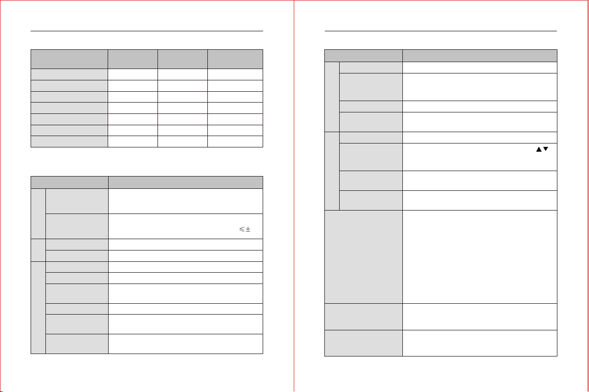
Item Item Description
Rated voltage
frequency
Allowable Voltage
range
Single phase/Three phase220VAC. Three phase
380V.50HZ/60HZ
Voltage fluctuate range: 220V:180V~264V ;380V:342~528V.
Voltage unbalance rate:<3%. Frequency fluctuation: 5%
Input
0~ three phase input AC voltage
0.1~400HZ.
Rated voltage
Frequency
Output
Modulation mode SPWM (sinusoidal PulseWidth modulation)
Control mode V/F control & sensorlessvector control
Digital setting :0.1HZ. Analog setting :Max.
Frequency x0.1%.
Frequency
resolution
Overload capacity 150% of rated currentfor 1 minute
Including the auto-torque .Auto-slipcompensation .
Start torque can be150% at 5.0HZ.
Torque
Characteristic
0.1~600 seconds ( 2 independment setting for
Accel/Decel time )
Acel/Decel Time
Control Function
Item Item Description
Adjustable V/F Pattern
V/F pattern
Operation frequency 0~50HZ . Output 0~100 %
rated current .
Starting time 0~5 seconds. Stop time 0-25seconds
DC Breaking
1.0~15.0KHZ
Carrier frequency
Stall prevention level
Frequency setting
20%~200% setting of ratedcurrent of inverter
according to the motorload characteristic
Control Function
Keypad .External terminal control . COM Serial control
Command
Keypad potentiometer setting . Operation panel
setting . external Terminal UP/DOWN setting .
Analog signal setting . 485 COM Setting.
Frequency setting
0-10VDC singal . Outputfrequency . current .output.
Multi-function
analog output
Programmable relay . opencollector output . Fault
signal output .
Output signal
Operation Function
AVR.Over voltage . Over-current stall prevention .
3-Groups fault records .Reverse inhibition .
Momentary Power loss restart. DC braking .
Auto torque& slip compensation. acceleration/
deceleration. S- curve .autotuning . adjustable
carrier frequency.Frequency limits . Parameterlock
/reset. Vector control . PIDcontrol . Counter .remote
control .MODBUS communication .Abnormal reset ,
Abnormal restart . energy saving running .sleep/
revival function . 1st/2nd frequency source selection .
Other Function
2.6 Technical Indication
LED Display can show the inverterrunning status. monitor
parameters. function parameters .errorand ect.
Optional parts selection braking assembly,remotekeypad and connection
cable and soon.
Chapter 2 Introduction to the ProductChapter 2 Introduction to the Product

-15-
-14-
Item Item Description
<0.5G
Vibration
Storage temperature -20 to 60
Ambient
IP20
Forced air cooling
Wall mounted
Protection Level
Cooling mode
Installation
Structure
Chapter 3 Installation and Wiring
3.1 Installation
3.1.1 Use theinverter in the following environmental conditions:
Altitude: Maximum 1000mabove sea level
Ambient Temperature: -10~+45 [Bare Machine: -10~+50 ]
Humidity: 20~90% RH(Non-condensing)
Ambient: Indoor places free from direct exposure to sunlight, dust,
corrosive gas, flammablegas, oil mist,steam, drip andsalt
Vibration: <0.5G
3.1.2 Installation Spaceand Direction
Toget better coolingeffect and convenienceof maintenance, the
inverter shall beinstalled vertically with enough space left (refer to the
figure 3-1). Whentwo and two more inverters are fixed in the same cabinet,
it is recommendedto fix them in parallel and horizontally to reduce heat
produced by them (refer to the figure3-2).When thereis amust to fix them
vertically, pleasefix an insulating board between them so that the heat
produced by the lower one could not have direct influence on theupper
one (refer tothe figure 3-3)
Figure 3-1 Installation
Space
Figure 3-2 Multi-piece
Parallel Installation
Figure 3-3 Multi-piece
Vertical Installation
Chapter 3 Installation and Wiring
Over Current .Over current.Under voltage .external
fault .Overload. Ground fault.Overheating .
Protection Function
Altitude 1000m or less.Keep from corrosive gas.
liquid and dust
Installation location
Ambient Temperature -10 to 40 ( -10 to 50 without blind plate )
Ambient Humidity Below 90% RH (no-condensing).
Ambient
Chapter 2 Introduction to the Product

-17-
-16-
Fig. 3-4
STPE 2.Install the optional interface boardat the position of keypad.(as
shown in the figure 3-5).
Fig. 3-5
3.2 Remote control keypads andwiring connection
STEP 1.Hand on thenotch of the two sides( rightand left) of the keypad and
pull it up by inward,remove thekeypad.(as shown in the figure 3-4).
STEP 3.Insert the optionalcable with the grounding side intothe slot of
interface board. (as shown in thefigure 3-6).
Fig. 3-6
STEP 4.Put the dismantledkeypad into the installation frame .Fix and
fasten it . Put the otherside cable insert into the keypad .(as shown in the
figure 3-7).
Fig. 3-7
Chapter 3 Installation and WiringChapter 3 Installation and Wiring
-19-
-18-
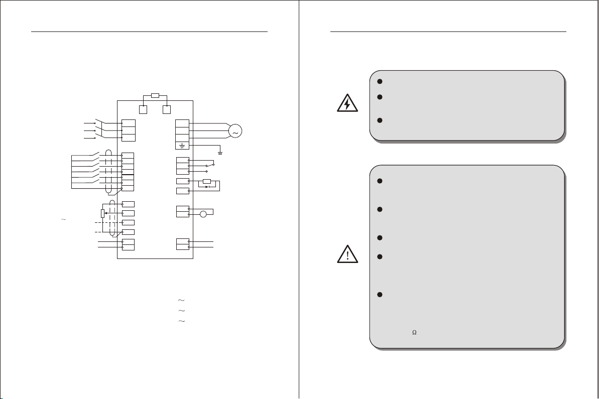
3.3 Wiring Diagram
3.3.1 Basic Wiring Diagram
Model : ZVF200-M0004S2 M0022S2
ZVF200-M0004T2 M0055T2
ZVF200-M0007T4 M0075T4
V
PDB
R
S
T
R
V
W
TA
TB
TC
Y1
12V
X1
X2
X3
X4
X5
X6
GND
AFM
GND
12V
COM
10V
AVI
AC1
GND
SG+
SG-
Braking Resistor
Fault Reley Output
M
TA-TB on when normal
TA-TC on when failure
Open collector
Output
Analog Signal Output
(0-10VDC)
12V Power supply
output Port
MOCB
Three phase
AC inpul
Power supply
Forward/Stop
Reverse/Stop
Reset
Multi-stage speed 1
Multi-stage speed 2
Multi-stage speed 3
Public Terminal
Potentiometer
Input or analog
Voltage Input
(0 10VDC)
Analog Current
Input (0-20mA)
485 COM Port
3.2.2 Cautions forWiring
HAZARD
Waitat least 10 minutes after powerOFF before opening
the front coverof the inverter.
Verify thecharge indicator lampis OFFbeforeproceeding
the work,and be surethat the voltage value of the main
loop terminal Pand DC- isless than 36VDC.
Theinternal wiring of the inverter should be operated
only by authorizedqualified people.
Verifythe rated inputvoltage of the inverter is matched
with AC power supply. Otherwise,there is thepossibility
of damage tothe inverter.
Install in orderand only operate wiring after finishing
main parts install ation. Otherwise, there is an electric
shock or damageto the inverter.
Do not performover-voltage withstand tothe inverter,
for this hadbeen done properlybefore EX-factory.
Be sure toinstall a no-fuse circui t breake r in the i nput
power supply side ofthe inverter to prevent expanding
of accident dueto an inverterproblem, which may cause
damage to thedistribution equipment orlead to fire.
Be sureto connect the ground terminal and the motor
casing to the ground wire whichmust be copper core.The
diameter of thecopper core should conform tothe relevant
national standard. Theground resistanc e should be less
than 10 .
WARNING
Fig.3-8
Chapter 3 Installation and WiringChapter 3 Installation and Wiring
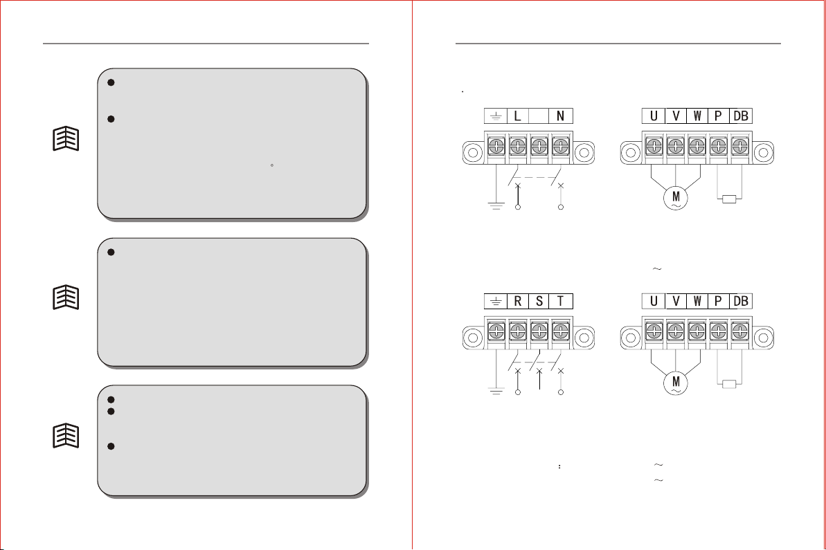
-21-
-20-
When theopen-ended output terminal of the collector
connects to any inductive load,i.e., therelay coil,do
insert a diodeat each endof the load in parallel.
The control wire in the inverter orthe control cabinet
should be atleast 100mm away from the power cable.
DO NOTput them in thesame metallic channel. If t he
signal wireand the power cable need to intersect, they
should intersect at an angleof 90 . The control wire
must adopt STP(shielded twisted pairwire); theshielded
layer must connectto the terminalGND; and the power
wire is recommendedto use metallicshielded cable.
TIP
TIP
The unavoidable strongelectromagnetic interferenceof
the inverter mayhave bad influenceon all the electrical
equipment andmeters inthe same environment. To reduce
interference, the output cable of the inverter can be
inserted in themetal pipe connectingto the ground or in
the metallic shielded cable, andconnect the metallic
shielded layer to the ground.In addition, amagnetic loop
put on the output cable is also effective to reduce
interference.
TIP
Input power RST disorder ,it can connectany one arbitrary
When inverter runsthe direction ofmotor isnot sameas
your required direction.Please change any twoof three
iuput motor wires
When inverter have disconnector toprotect current leakage.
In order to avoidsomething wrong withdisconnect ,please
choose current leakage above 200mA and fi nish it
within more than 0.1 second
3.3.3 Instruction onMain Circuit Terminals
1 The main circuit terminals are shown as in the figure 3-9~3-10.
Fig.3-9 Diagram 1for Main CircuitTerminals
Earthing Single phase
220V input
Connect with the
braking resistor
Fig.3-10 Diagram 2for Main CircuitTerminals
Model ZVF200-M0004T2 M0055T2
ZVF200-M0007T4 M0075T4
Connect with
three-phase AC motor
Model: ZVF200-M0004S2 M0022S2
Earthing Three-phase
220V/380V Input
Connect with
three-phase AC motor
Connect with the
braking resistor
Chapter 3 Installation and WiringChapter 3 Installation and Wiring

-23-
-22-
2 Function Description on Main Circuit Terminals
Terminal Symbols Function Description
AC line inputterminals, connecting with three-
phase 380V or220V ACinput
AC line inputterminals, connecting with single-
phase 220VAC input
Inverter output terminalsconnecting with
three-phase AC motor
RST
LN
UVW
PDB
G Ground terminal connectingto the ground
External braking resistorterminals, connecting with
two side ofthe external braking resistor
3.2.4 Description ofterminal of thecontrol circuit
1.The terminal ofcontrol circuit shown in Fig 3-11.
Fig 3-7 Controlcircuit terminal
Type Terminal
Symbols Function Description Electrical Specifications
X1
X2
X3
X4
X5
X6
Xn (n=1, 2, 3,6)-GND is
Validonly when there isa
short circuit Thefunctions
can be set bythe parameter
P38 P42
INPUT, 0~12Vpower level
low level valid, 10mA
Multi-function
Input Terminal
Multi-function open collector
output is defined as on-off
output terminal, whose function
is set by the parameterP45
with reference of GND
OUTPUT, Maximum
Current Load I 50mA
Multi-function
Output Terminal
Y1
Analog signal public
terminal
Public
port
GND
External analog preset power
supply, connecting to
potentiometer together with
termianl GND andAVI.The
frequency can be set as
required
Output,10VDC
+10V
Analog voltage singal input,
with reference of GND Input .0 10VDC
AVI
Analog current Singal input,
with reference of GND Input .0 20mA
ACI
Program mable Analog voltage
output P43 with reference of
GND
Output .0 10VDC
AFM
Analog Input Output terminal
2. Description ofthe control circuitterminal
Chapter 3 Installation and WiringChapter 3 Installation and Wiring
-25-
-24-
Type Terminal
Symbols Function Description Electrical Specifications
Power
port
12V 12VDC output(control
power) 12VDC 100mA
Relay contact output.
when normal TA andTB ON,
TA-TC off.Action TA and
TB off,TA-TCON.Set by P46
Contact rated value
NO 250VAC-5A
NO 250VAC-3A
Programmable
output terminal
TA
TB
TC
Communication singal
positive port
Communication singal
negative port
SG+
SG-
COMMUNICATION
PORT
Inverter Models Break
Switch (A)
2
Main Circuit mm Control
2
Wire (mm )
Input Wire Output wire
ZVF200-M0004T2/S2
ZVF200-M0007T2/S2
ZVF200-M0015T2/S2
ZVF200-M0022T2/S2
ZVF200-M0037T2
ZVF200-M0055T2
ZVF200-M0007T4
ZVF200-M0015T4
ZVF200-M0022T4
ZVF200-M0037T4
ZVF200-M0055T4
ZVF200-M0075T4
5/15
10/20
20/30
30/50
40
50
5
10
15
20
30
40
2.5
2.5
2.5
4
6
6
2.5
2.5
2.5
4
4
6
0.75
0.75
0.75
0.75
0.75
0.75
0.75
0.75
0.75
0.75
0.75
0.75
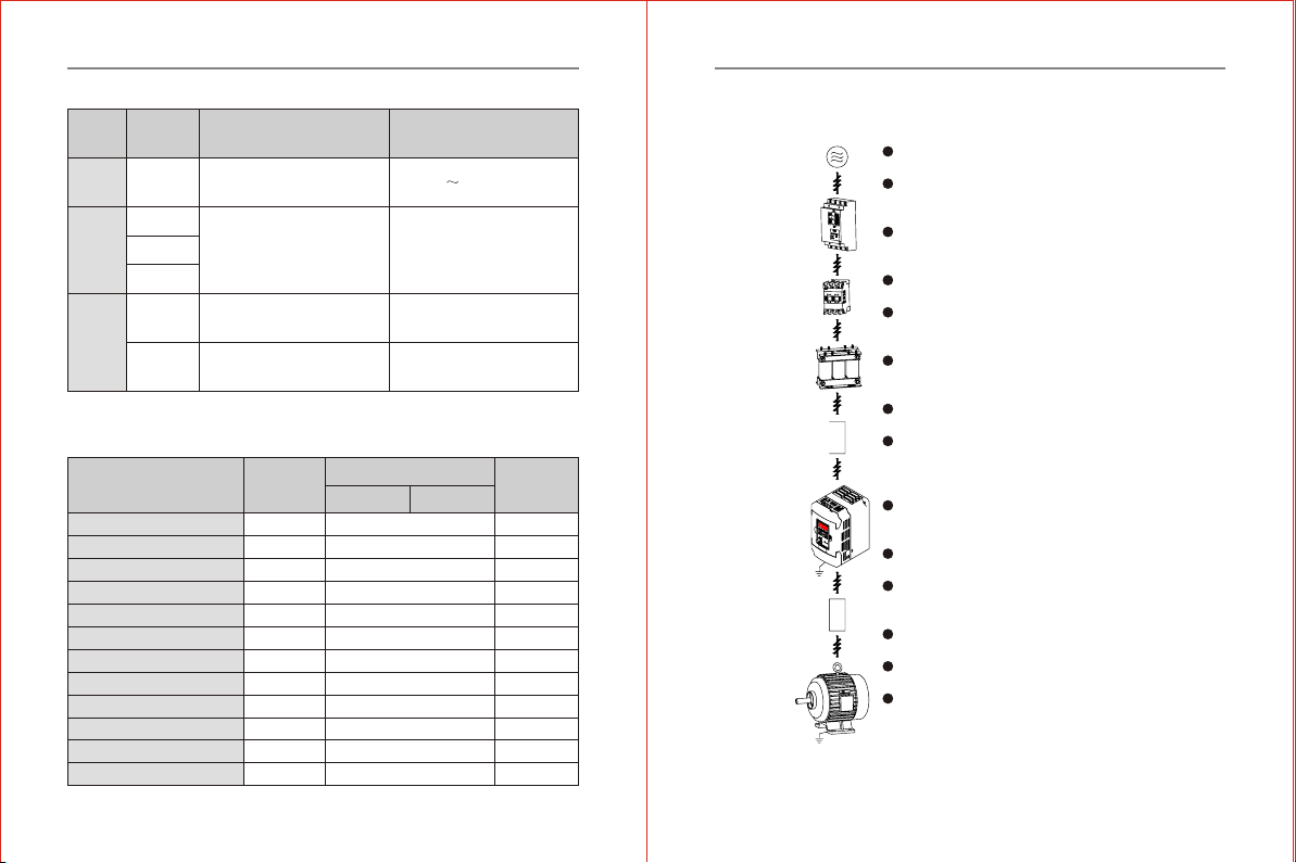
3.4 Inverter SystemWiring
Power Supply
Please follow the specificpower supply requirem ent
shown in .Avoid theinverter damage .
Be sure toinstall No-Fuse breaker between the AC
power and inverter .
No-Fuse breaker
Make sure use theNo-fuse that matched with the rated
voltage and currentof theinverter for ON/OFFcontrol.
and for the inverterprotection .
No-Fuse breakers can notused as START orSTOP control.
Magnetic contactor
Please do not usea magnetic contactor as theI/O switch
of the inverter thiswill reduce the operatinglife cycle
of theAC inverter .
Please do notuse the magnetic contactor as START
and STOPof the inverter .
AC Input Reactor
AC linereactor should be installedwhen thepower
supply capacity is500kVA.
Used to improve theinput power factor,to reduce
harmonics and provide protectionfrom ACline
disturbances. (Surge,switchingspike, power flick,etc.)
Input Filter
There have inductive loadbeside the inverter .The input
filter should be installed.
Inverter
The ACinput line connect withR.S.T or L.N. Nophase
different .
The output connect withU.V.W .It onlychange anytwo
phase among the three phases ifthe inverter run forward.
while the motorrun reverse .
The output terminalcan not connect withAC inputline.
Avoidthe inverter damage .
Good connection with earthground .
Output filter
It's necessary to installon the inverter output side when
the inverter interfered by the sensitive equipment.and
can reduce the electromagneticinterference.
Power Supply
No-Fuse
breaker
Magnetic
contactor
AC Input
Reactor
Input Filter
Inverter
Output filter
Three phase
motor
Fig.3-12
Chapter 3 Installation and WiringChapter 3 Installation and Wiring
Capacity of breakswitch and section area of wire
-27-
-26-
Chapter 4 Operation panel and Operation
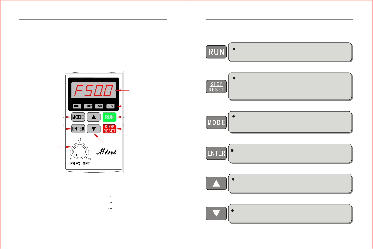
4.1.1 Operation Panel
4.1 Operation Paneland Description
4.1.2 Function Descriptionon Keys
Run Key. When the run command selected bey the keypad control
(P01=00).Press this key and the inverter start running .
STOP/RESET key. when the run command is selected by the keypad
control .(P01=00). The inverter is under normal running. Press this key
to stop running.When the inverter is in the state of failure alarm.Press
this key remove the fault .and return to the normal status .
Program/Function mode key Press this key to displays the AC drive
status, setting frequency .output current . FW D/REV. pa ram ete rs
settings and so on.
E nter/Store key. Press this key to confirm the current status of the inverter
or save the current parameter value.
Up key. Press this key, the data or parameter code will go up. Press and
hold it, the modifying speed upward will rise.
Down key. Press this key, the data or parameter code will go down. Press
and hold it, the modifying speed downward will rise.
ENTER/STORE Key
MODE Key
program/function mode
LED display
display frequency,
current, parameters,
error and etc.
RUN Key
STOP/RESET Key
LED Indicates
Lamp lights during RUN,
STOP,FWD & REV
operation.
UP and DOWN Key
Panel Potentiometer
Fig.4-1 ZR06 OperationPanel Description
Model: ZVF200-M0004S2 M0022S2
ZVF200-M0004T2 M0055T2
ZVF200-M0007T4 M0075T4
Chapter 4 Operation panel and Operation Chapter 4 Operation panel and Operation
-29-
-28-
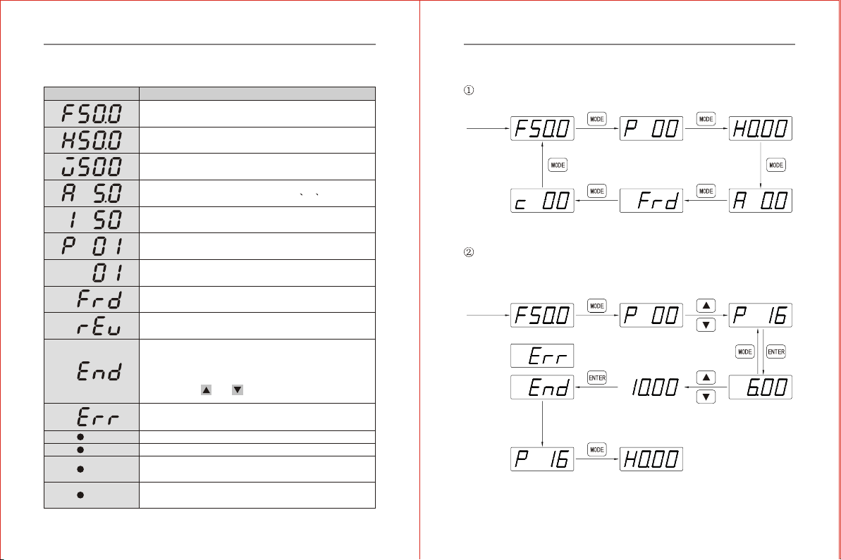
4.1.3 Function Descriptionon Operation PanelIndicator Lights
Display Status Function Description
The ACdrives master frequency.
The actual running frequency
The customer unit(V)
The output current presetat terminal U V W
Run program automatic
Parameter item
Parameter value
the inverter is inthe state of forwardrunning.
the inverter is inthe state of reverserunning
"End" displays for approximately1 second if inputhas been
accepted. Aftera parameter value hasbeen set, the new
value is automaticallystored in memory. To modify an
entry, usethe and keys.
"Err" displays, if theinput is invalid.
When the light is ON,inveter is running
When the light is ON,inverter will stop
When the light is ON, the inverteris in the state of forward
running
When the light is ON, theinverter is in the state of reverse
running.
RUN
STOP
FWD
REV
State parameter view
Modification of parametervalue (modify the parameter value for P16
jog function from 6.00Hz to 10.00Hz).
Initializing
Initializing
Data fault
Data right
For a second
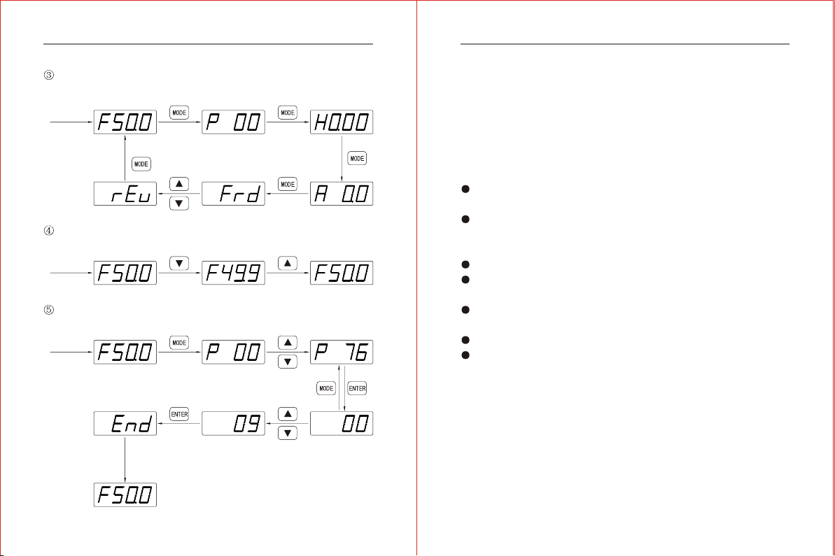
4.1.4 Use ofOperation panel
Chapter 4 Operation panel and Operation Chapter 4 Operation panel and Operation
-31--30-
When running modeis controlled by keypads, revise the methods of
running direction
Initializing
Press two times
When frequency isset by key up and down
Initializing
Parameter initializing (restoreto the factorydefault setting 50.00Hz)
Initializing
Data right
For a second
Chapter 5 Inverter Use
5.1 TrialOperation
5.1.1 Safety Instructionon Trial Operation
The following steps should be inspected and confirmed beforethe trial
operation of theinverter:
Be sure theapplication ambient andinstallation for the inverter is in
accordance with therequirements specified inClause 3.1.
Be sure themain circuit iscorrectly wired. The inputpower supply of
the inverter mustbe connected tothe terminal R, Sand T or L,N. The
output terminal U, V and W mustbe connected tothe motor.
Be sure theground terminal isgood grounded.
Be sure all the switches and terminals are in proper state of off or
shut down.
Be sure thereis no shortcircuit or shortto ground of allthe terminals
and electrified parts.
Be sure allthe terminals, connectorsand screws aretightly fastened.
Be sure themotor has noother loads.
5.1.2 TrialOperation
Try thisstep only aftercareful inspection as mentioned in the clause
5.1.2. While in trial operation, it is suggested that the motor without
load to avoid damage to this mechanical equipmentarising from incorrect
operation. During trial operation, if the operating instruction is P01,
then the RUN/STOP key control (factory default setting)of the operation
panel must be selected. The trial operation steps must be followed as
shown in thetable 5-1 below.
Chapter 5 Inverter Use
Chapter 4 Operation panel and Operation
-33--32-
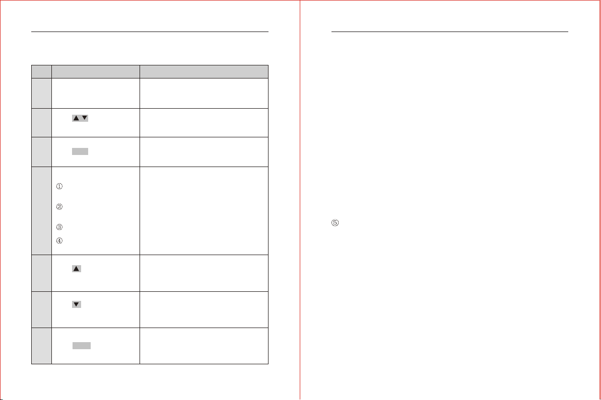
Table 5-1Trial OperationSteps
Order Operation Description
After energized, the inverter is in the state
of readiness and LEDdisplays F50.00Hz.
the built-in cooling fanbegin to work.
Motor begins running, the frequency
rise from H0.00Hz toH5.00Hz, under the
frequency monitor
If there is anyanomaly or tripping, stop
running immediately and cut off thepower
supply.
Please refer toChapter 7, find the trouble
causes, then proceed trialoperation again
after troubleshooting.
If the motor runsin the wrong direction,
change arbitrary two-phase connectionof
the output terminal U,V orW.
Go to the nextstep if everything isnormal.
The motor accelerates rotating and the
displayed frequency rises from H5.00Hz to
H50.00Hz. Go to thenext step if everything
is normal.
The motor decelerates rotatingand the
displayed frequency falls from H50.00Hz to
H0.00 Hz.Go to thenext step if everything
is normal.
Theinverter stops outputting,the motor
stops running and the trial operationends.
If everything is normal,please repeat the
operation for severaltimes.
Switch on, inverter
energized.
Press RUN .
Keep a close eyeon the
following points:
if there is anyabnormal
vibration or noise whenthe
motor runs.
if there is anytripping or
other abnormality of the
inverter.
If the motor runsin the
correct direction.
if the value forrotation
speed and frequency iscorrect.
Press continuously till
LED displays F50.00Hz.
Press continuously till
LED displays F0.00Hz.
Press STOP.
1
Set the frequency toF5.00Hz. This stepcan
be left out ifthe displayed frequency is
already F5.00Hz when energized.
Press / till LED
displays F5.00Hz.
2
3
4
5
6
7
5.1.3 Cautions forOperation
All the inverterfunctions are determined by set parameters. The
parameters of inverter ZVF200 series consist of the function codes
P00~P157, see the detail in Chapter 6 of this manual. The displayed
parameter value ofeach function code is the factory default value of the
inverter before EXfactory, which can be modifiedby the useraccording
to his needs. It is noteworthy that a user shall changethe relative function
parameters when heamends a parameter because some of the parameters
are inter-related . It is not recommended tomodify the setparameter value
if there isno special requirement, for the factory default setting has been
done properly. Otherwise, this may cause damage to the inverter or
equipment due toerror parameter.
In case thereis an erroralternation of theparameter,please initialize
the parameter withreference to the operation method in the clause 4.1.4
Parameter Initializing RestoringFactory Default Settings.
Chapter 5 Inverter UseChapter 5 Inverter Use

-35--34-
P00-Master frequency sourceselection .
If the setvalue 04 Panel Potentiometer setting.
P01-Source of operationcommand .
If the valueis 0 keypad control
Run or stopthe inverter with or keyson theoperation panel.
Adjust thespeed by turningthe potentiometer on the operate panel .
Three-phase
AC Power
Supply
Relay Failure
Output
Voltage Output
V
M
MCCB
R
S
T
U
V
W
G
TA
TB
TC
GND
AFM
5.2.2 Eg.2: Startand stop theinverter with theexternal terminal ,
feed the frequencywith external potentiometer .
5.2.1 Eg. 1:Run or stopthe inverter withoperation panel, andfeed the
frequency with panelpotentiometer .
P00-Master frequency sourceselection .
The set value01 is external voltage or external potentiometer value .
P01-Source of operationcommand .
If the value is 01- Externalterminal control .
P38- The inputterminal X1.2 function selection .
The value 00-Two Wirerunning control
P39-Input terminal X3function selection .05-External reset input.
X1-GND switch on. The motorrun forward .
X2-GND switch on . The motorrun reverse .
X1 X2-GND both switch onor switch offat the same time.The inverter
will stop .The fault alert X3-GND switch on . the fault reset.
The speed controlby the regulating value of AVI .(controlled by
4.7-10K/2W potentiometer control.)
Fig. 5-2
Relay Failure
Output
Voltage Output
R
S
T
U
V
W
G
TA
TB
TC
GND
AFM
Forward
Reverse
Reset
FWD
REV
X1
COM
+10V
AVI
GND
Fig.5-1
Three-phase
AC Power
Supply
MCCB
5.2 Examples ofUse
This manual providesthe following examplesfor users' referenceon
the use ofinverter.
VV
MM
Chapter 5 Inverter UseChapter 5 Inverter Use
4.7-10K/2W
This manual suits for next models
12
Table of contents
Other Chziri Inverter manuals


