CIAC Outdoor Series User manual

VERSION: A
DATA:Aug,12th,2016
SEVICE MANUAL
AHU VALVE BOX

Contents
1. General Information................................................................................................................................ 1
2. Specication ........................................................................................................................................... 4
3. Dimension............................................................................................................................................... 5
4. Wiring diagram ....................................................................................................................................... 7
5. Installation .............................................................................................................................................. 8
6. PCB photo ............................................................................................................................................ 26
7. Dip switch setting.................................................................................................................................. 27
8. Failure code.......................................................................................................................................... 29
9. Troubleshooting.................................................................................................................................... 30
APPENDIX Sensor resistance table........................................................................................................ 34

1
1. General information
1.1 Function:
Thought AHU valve box, can realize the CIAC IMVF outdoor unit connect with third party DX air handling units. As the folowing gure
1.2 Feature:
(1) EXV part and control part integration, easy for translation and installation. Gas pipe is integrated into
the valve box.
(2) Optional insttion location: can choose lting or nailed to the wall
(3) Control box location changeable :
Control box can be separately with EXV box.(2 meter)
Control box can be front or back of EXV box, easy installation.
(4) Broad capacity: 5-20HP
(5) High Compatible:
Same PCB board with IMVF indoor, easy operation and service.
Same wired controller can be used with IMVF indoor unit such as YR-E16,YR-E17 and YR-E14
(6) Reliable EEV : EEV is supplied by FUJIKOKI.
2
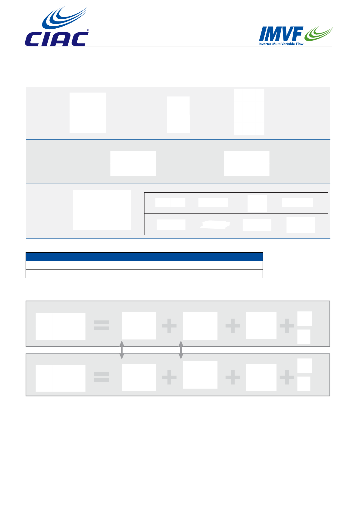
1.3 System lineup
MRV III-C
MRV Outdoor
Valve Box
AHU &
MRV indoor
MRV III-S
8/10/12HP
AH1-280A
AHU need purchase in Market
5HP(14KW) <Connected AHU capa. ≤10HP(28KW) 10HP <Connected AHU capa. ≤20HP(56kw)
AH1-560A
MRV III-C PLUS MRV IV-C
1.4 Conguration
AH1-280A
Different Valve Same Control Parts
EXV part Control Part Sensor and wire Controller
OR
AH1-560A
OR
Outdoor series Outdoor model
IMVFIII-C (2200V) CA43BV***-V5J1H
IMVFIII-C (460V) CA43BV***-V6J1H
The AHU valve box can connect with the following outdoor units:
3
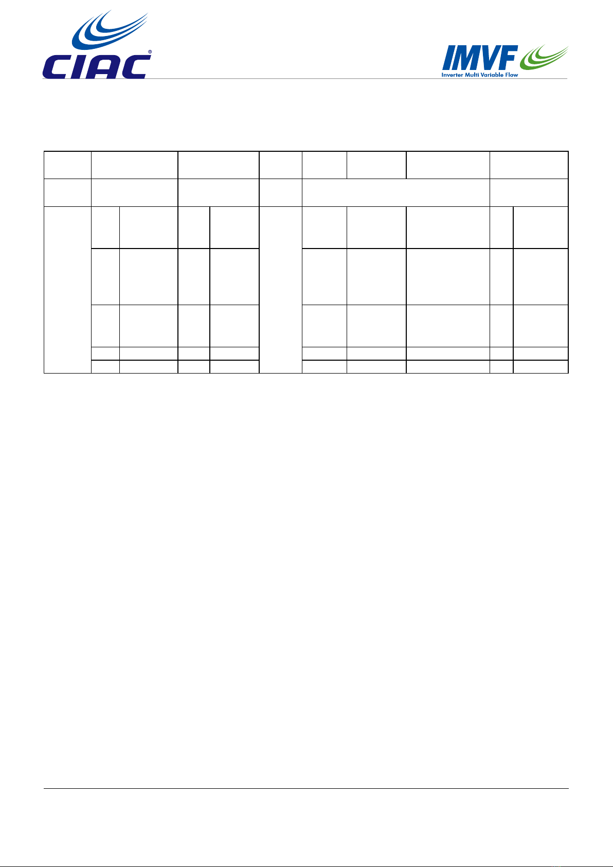
1.5 Nomenclature
Code
position 1,2 3 4 5 6 7 8
Code
meaning Valve box series Valve box type Space
mark
Indoor capacity which Valve box can be
connected Series number
Code and
contents
VP 3-pipe valve
box 1 1 to 1
-
Cooling
capacity
Cooling
capacity<
99KW
Three digits***(unit:
100W) AFirst
generation
MS
IMVF
+SUPER
MATCH
valve box
2 1 to 2 Cooling
capacity
Cooling
capacity>
99KW
Three digits 000
(unit
:
HP) B Second
generation
AH
IMVF +
AHU valve
box
3 1 to 3 Cooling
capacity
Cooling
capacity is
not dened
Three digits 000 C Third
generation
4 1 to 4 … …
… … … …
4
2. Specication
Model AH1-280A AH1-560A
Connected AHU capacity 14≤x ≤28KW(5-10HP) 28 <x ≤56KW(10-20HP)
Power supply 220-240V/50/60Hz 220-240V/50/60Hz
Dimention(W/D/H) 350/226/155 433/296/193
Shipping dimensions 606*295*209 667*365*249
Material Galvanized steel Galvanized steel
Color Grey Grey
Weight/kg 6 9
Shipping Weight/kg 8 12
Liquid pipe (mm) 9.52(Main)/12.7 12.7(Main)/9.52/15.88
Gas pipe (mm) 25.4(Main)/22.2 /19.05 28.58(Main)/25.4/22.22
Pipe connection method Flare connection and welding Flare connection and welding
Branch box-Indoor Max Single pipe length/m 5 5
Branch box- indoor max drop/m 5 5
Height Drop between branch box /m 15 15

5
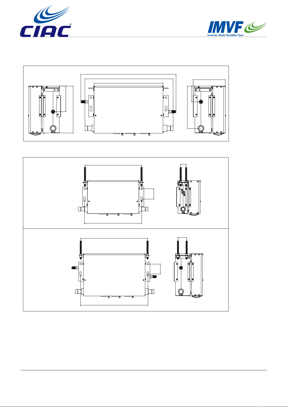
3. Dimension
AH1-280A
240
226
179
166
56
44
13
195
147
12
36
49
82
9
155
476
419
350
15
14
84
86
152
80
195
163
78
6
AH1-560A
13
59
161
266
296
309
433
501
597
553
14
84
78
87
192
201
99
266
193
12
39
83
9
7
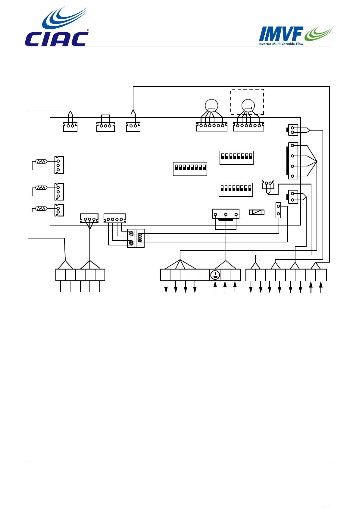
4. Wiring diagram
SW01 ON
12345678
CN10CN15
CN18
CN19
CN20
CN16
CN3
CN7
CN1
TC2
TC1 ON
SW07
Outdoor
unit
Controller
12345678
ON
SW03
Power
Input 220V
FAN Speed
AC 220V
Output
DC 12V
12345678
6.3A 250VAC
FUSE1
PMV1
M
P Q A B C LH M L N V1 V2 D1D2 P1 P2N
CN24CN22
TA
CN31
CN33
CN8
{
{
{
{
Input
ON/OFF
{
Output
Dry
contact
{
Output
AC 220V
{
{
K1 K2
CN13 CN12
PMV2
M
8
5. Installation
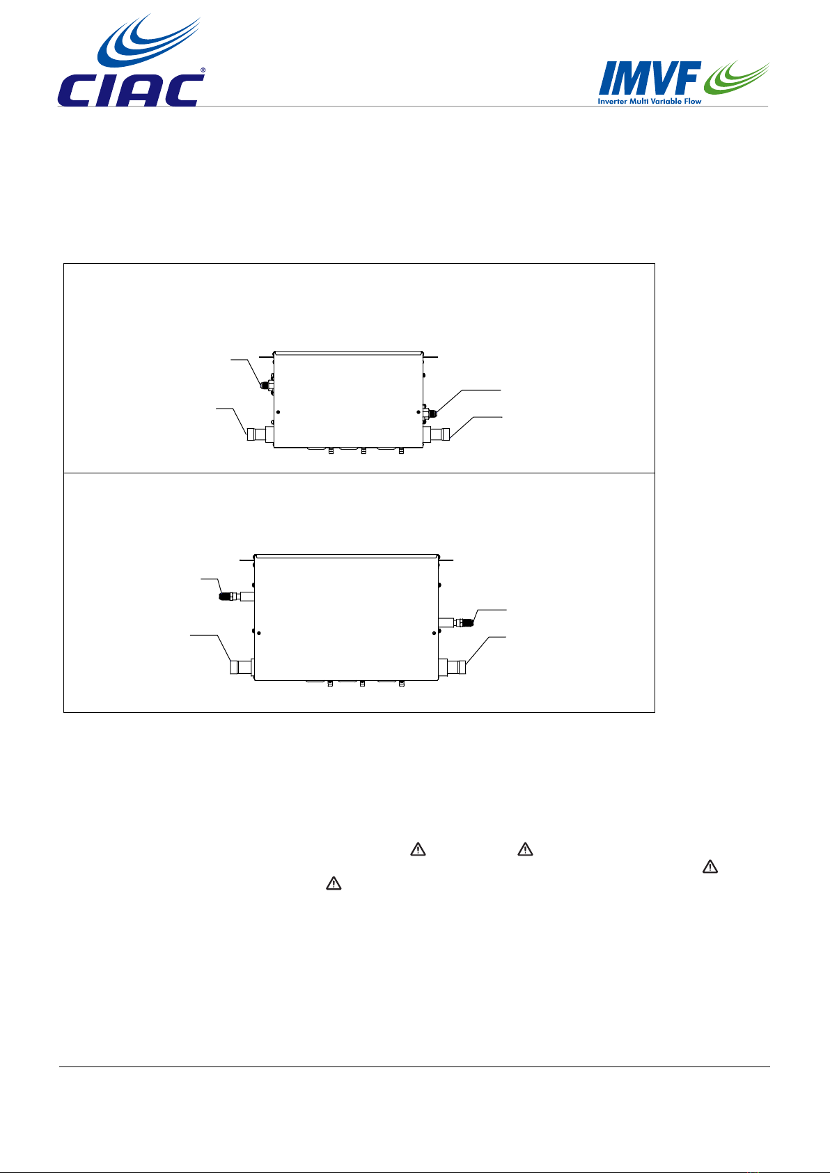
5.1 Parts and function
Outdoor unit side (2 pipes)
Outdoor unit side (2 pipes)
Indoor unit side (2 pipes)
Indoor unit side (2 pipes)
Liquid Pipe (Ø9.52)
Liquid Pipe (Ø12.7)
Liquid Pipe (Ø12.7)
Liquid Pipe (Ø9.52)
Gas Pipe (Ø25.6)
Gas Pipe (Ø28.8) Gas Pipe (Ø28.8)
Gas Pipe (Ø25.6)
AH1-280A
AH1-560A
5.2 Safety
• If the connection kit is transferred to a new user, this manual shall be transferred to the user, together with the
conditioner.
• Before installation, be sure to read Safety Considerations in this manual for proper installation.
• The safety considerations stated below is divided into “ Warning” and “ Attention”. The matters on severe
accidents caused from wrong installation, which is likely to lead to death or serious injury, are listed in “
Warning”. However, the matters listed in “ Attention” are also likely causing the severe accidents. In general,
both of them are the important items related to the security, which should be strictly abided by.
• After the installation, perform test run to make sure everything is in normal conditions, and then operate and
maintain the connection kit in accordance with the user manual. The user manual should be delivered to the user
for proper keeping.

9
• Please ask the special maintenance station for installation and repair. Water leakage, electric shocks or re
accidents might be caused from improper installation if you conduct the installation by your own.
• The installation should be conducted properly according to this manual. Water leakage, electric shocks or re
accidents might be caused from improper installation.
• Please make sure to install the connection kit on the place where can bear the weight of the connection kit. The
connection kit can’t be installed on the grids such as the non-special metal burglar-proof net. The place with
insufcient support strength might cause the dropdown of the machine, which may lead to personal injuries.
• The installation should be ensured against typhoons and earthquakes, etc. The installation unconformable to the
requirements will lead to accidents due to the turnover of the machine.
• Specic cables should be used for reliable connections of the wirings. Please x the terminal connections reliably
to avoid the outside force applied on the cables from being impressed on the cables. Improper connections and
xings might lead to such accidents as heating or re accidents.
• Correct shapes of wirings should be kept while the embossed shape is not allowed. The wirings should be reliably
connected to avoid the cover and the plate of the electrical cabinet clipping the wiring. Improper installation might
cause such accidents as heating or re accidents.
• While placing or reinstalling the connection kit, except the specic refrigerant (R410A), don’t let the air go into the
refrigeration cycle system. The air in the refrigeration cycle system might lead to the cracking or personal injuries
due to abnormal high pressure of the refrigeration cycle system.
• During installation, please use the accompanied spare parts or specic parts. If not, water leakage, electric
shocks, re accidents or refrigerant leakage might be caused.
• During installation, if refrigerant leakage occurs, ventilation measures should be taken, for the refrigerant gas
might generate harmful gases upon contacting the ame.
• After installation, check if any refrigerant leakage exists. If the refrigerant gas leaks in the room, such things as
air blowing heaters and stoves, etc. may generate harmful gases.
• Don’t install the connection kit at the places where the ammable gases may leak. In case the gas leakage
occurs around the machine, such accidents as re disasters may be caused.
• The refrigerant gas pipe, HP gas pipe and liquid pipe should be heat insulated to preserve heat. For inappropriate
heat insulation, the water caused from the condensation will drop to get the article at home wet.
• The electrical construction shall be implemented by the correspondingly qualied personnel in accordance with
electrical construction standards, local electrical laws as well as specications. Moreover, dedicated circuit must
be used, rather than the wire pin. Insufcient capacity of the wire circuit and unprepared construction (if any) may
cause electric shock, res, etc.
• During the process of grounding, the ground wire cannot be connected to the gas pipe, water pipe, lightning rod
and ground wire of the telephone. Incomplete grounding may cause electric shock, res, etc.
• Install residual-current circuit breaker, or electric shock, res, etc. will occur.
• When contacting electrical components, ensure they are powered off. Contacting the live part may result in the
danger of electric shock.
• If there is leakage of the refrigerant gas ow during operation, refrigerant gas is required. If the refrigerant gas
contacts any re, poisonous gases will be produced.
• If the supply cord is damaged, it must be replaced by the manufacturer, its service agent or similarly qualied
persons in order to avoid a hazard.
Warning
10
• This appliance is not intended for use by persons (including children) with reduced physical, sensory or mental
capabilities, or lack of experience and knowledge, unless they have been given supervision or instruction
concerning use of the appliance by a person responsible for their safety.
• Children should be supervised to ensure that they do not play with the appliance.
• This appliance can be used by children aged from 8 years and above and persons with reduced physical, sensory
or mental capabilities or lack of experience and knowledge if they have been given supervision or instruction
concerning use of the appliance in a safe way and understand the hazards involved. Children shall not play with
the appliance. Cleaning and user maintenance shall not be made by children without supervision.
• The appliances are not intended to be operated by means of an external timer or separate remote-control
system.
• Keep the appliance and its cord out of reach of children less than 8 years.
Attention
• The connection kit should be effectively grounded. Electric shocks may occur if the connection kit is ungrounded
or inappropriately grounded. The wire for earthing shouldn’t be connected to the connections on the gas pipe,
water pipe, lightning rod or telephone.
• The breaker for electricity leakage should be mounted. If not, accidents such as electric shocks may happen.
• The installed connection kit should be checked for electricity leakage by being powered.
• After installation, all cassette concealed connection kites should be trial-tested. After the proper operation of the
machine, other tments can be made.
• When installing the connection kit, please x the box and connecting pipes in an efcient way to avoid shaking
when changing connection kit.
• If the ambient humidity bigger than 80%, when the water discharge hole be blocked or the lter becomes dirty,
or airow speed change, there may be leads to condensing water drop down, and at the same time there maybe
some drops of water spit out.
• Keep the connection kit, power supply wiring, conductor, etc. at least 1 m away from the TV and radio to avoid
image interference and noise. However, sometimes there is still noise when the distance is over 1 m due to the
different states of radio waves.
• Try to install connection kit where the uorescent lamp is far away.
• When wireless devices are being installed, the distance that the signal from the controller will reach may be
shortened in a room with a uorescent lamp that is turned on in an electric way (frequency conversion or rapid
start).
Prohibitions
• Do not use components other than the fuse of proper capacity, such as metal wire and copper wire, which will
cause res and other faults if used instead of the fuse.
• When doing the cleaning and maintenance, make sure that the operation has been stopped and the manual
power switch is in the off position.
• Do not use appliances such as water heater near the connection kit. Using appliances producing steam near the
connection kit may lead to accidents such as water leakage, electric leakage and short circuit when the cooling
system is in operation.

11
5.3 Installation instruction
Do not install at such places
Attention item
Accessories
1. A place that is lled with mineral oil, a kitchen which has oil and steam everywhere, etc., which may cause
degradation, falling off and water leakage of the resinous components.
2. A place with corrosive gases such as sulphurous acid gas, which will lead to the corrosion of the copper tube,
welding joint, etc., causing refrigerant leakage.
3. A place where machines give out electromagnetic waves, which will lead to abnormality and improper function of
the control system.
4. A place with possible leakage of combustible gases, oating of carbon ber and combustible dust and use of
volatile combustible substances such as diluents, the accumulation of which around the machine set will lead to
res.
5. A place where small animals inhabit, whose contacting the inner electrical components may cause faults,
smoking, outbreak of a re, etc.
6. A coastal place with high salinity and a place with great variation in voltage such as a factory, which may cause
faults to vehicles and ships.
Install after making sure that the type of the refrigerant used is R410A. If any other type of refrigerant is used, the
machine cannot run.
• Before and after the unpacking, if connection kit is to be moved, the hoisting handles (totally 4) shall be held
rmly. Do not apply force to other parts, especially a refrigerant tube and an electrical cabinet.
• Concerning the installation of the outdoor and indoor units, refer to the installation specication of each unit.
Conrm that the accessories below are packed together.
AH1-
280A Variable diameter suspending clip
Thermal
insulation
pipe
Nut Specication
Quantity 2 2 2 2 8 2 2 2 1
Shape
Ø12.7
Ø9.52
inner diameter Ø19.3
inner diameter Ø22.4
outer diameter Ø25.4

12
<Entrustment>
Before the installation is completed, do not abandon the accessories needed in installation.
Combinations
• The connection kit is special used for third party air handling units. Cannot connect to other indoor unit.
• Please according to the following table to select the connection kit model.
Table1: Total capacity of indoor unit:
Connection kit The capacity of the air handing unit (kW) The quantity of the air handing unit
AH1-280A ≤28kW 1
AH1-560A 28kW<Capacity≤56kW 1
(2) Inspection upon delivery
Inspection item Inspection column
If the electric box cover is installed
If the installation specication is transferred to the customer
Inspection item
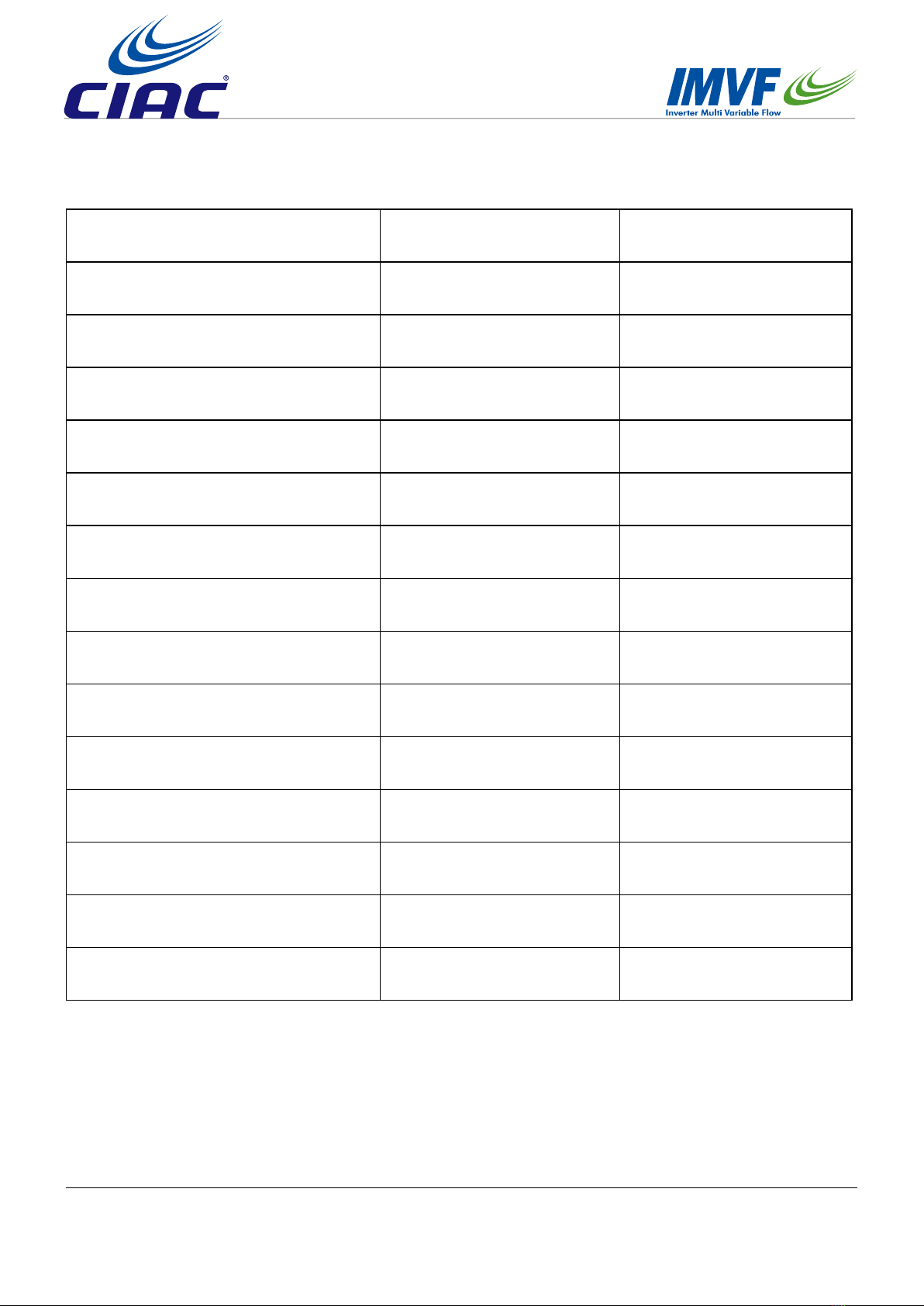
Pay much attention to the following during installation. Check them again after completion.
(1) Inspection items after installation
Inspection item Defect Inspection column
If the installation of connection kit is secure ? Falling off, vibration and noise
If gas leakage inspection is completed ? No heating/cooling
If complete insulation is achieved
(refrigerant piping and tubing connections) ? Water leakage
If the voltage of the power supply is
consistent with that on the nameplate ? Out of service, burnt
If there is improper wiring or piping ? Out of service, burnt
If there is construction without grounding ? Danger in electric leakage
If the thickness of the wire is as specied ? Out of service, burnt
AH1-
560A Variable diameter suspending clip screw
Thermal
insulation
pipe
Nut Specication
Quantity 2 2 2 2 8 8 2 2 2 1
Shape
Ø15.88
Ø12.7
inner
diameter
Ø22.4
inner
diameter
Ø25.6
outer
diameter
Ø28.58
13
5.4 Installation procedure
5.4.1 Pre-installation
The installation location selected shall meet the following conditions and be approved by users.
• The strength shall be sufcient to withstand the weight of the connection kit
• There is no signicant tilt on the plane.
• Ensure that there is enough space for installation and maintenance.
• There is space for inspection on the side and top of the electric box
• The length of piping between the indoor and outdoor units shall be within the permissible range (referring to the
specication attached to the outdoor unit).
• Please install the connection kit in places where noise will not inuence the customers too much (such as
washroom, passageway, warehouse, equipment room, etc.). Places with high requirement for quiet are not
suggested for installation, such as bedroom, drawing room, meeting room, ofce, etc.
Note:
• the electrical box can be changed as show in 3 connection kit installation.
• When starting up, stop, defrosting, and oil-returning in heating mode , the 4-way valve will veer and create noise.
This kind of noise is normal for the running of connection kit.
• A noise may be emitted by the connection kit as a result of control during operation or stopping of an indoor unit.
If it is installed in the ceiling where it is exposed, take adequate precautions with the installation location.
<Notice item>
• Inspect whether the installation location can sufciently withstand the weight of connection kit and set the hoisting
bolts by reinforcing the beam if necessary. Use hoisting bolts in installation (referring to 2 for the preparation
before installation).
• Install the power wiring and power line of the connection kit at more than 1 m away from TV and radio to prevent
the image clutter and noise. But, there may be noise even if it is more than 1 m according to the different waves.
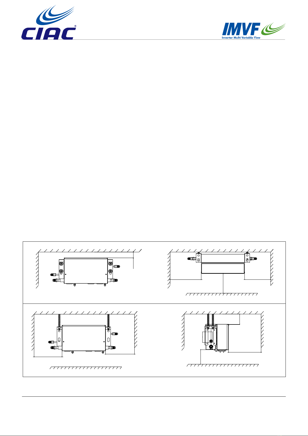
Min100
Front view
Min200 Min200
Min300
Top view
Wall mounted (mm)
Celing mounted (mm)
Front view Side view
Min200
Min200
Min300
Min50
Min50

14
Electrical box
Manhole must
be arranged
on the side of
the electrical
box
500
500
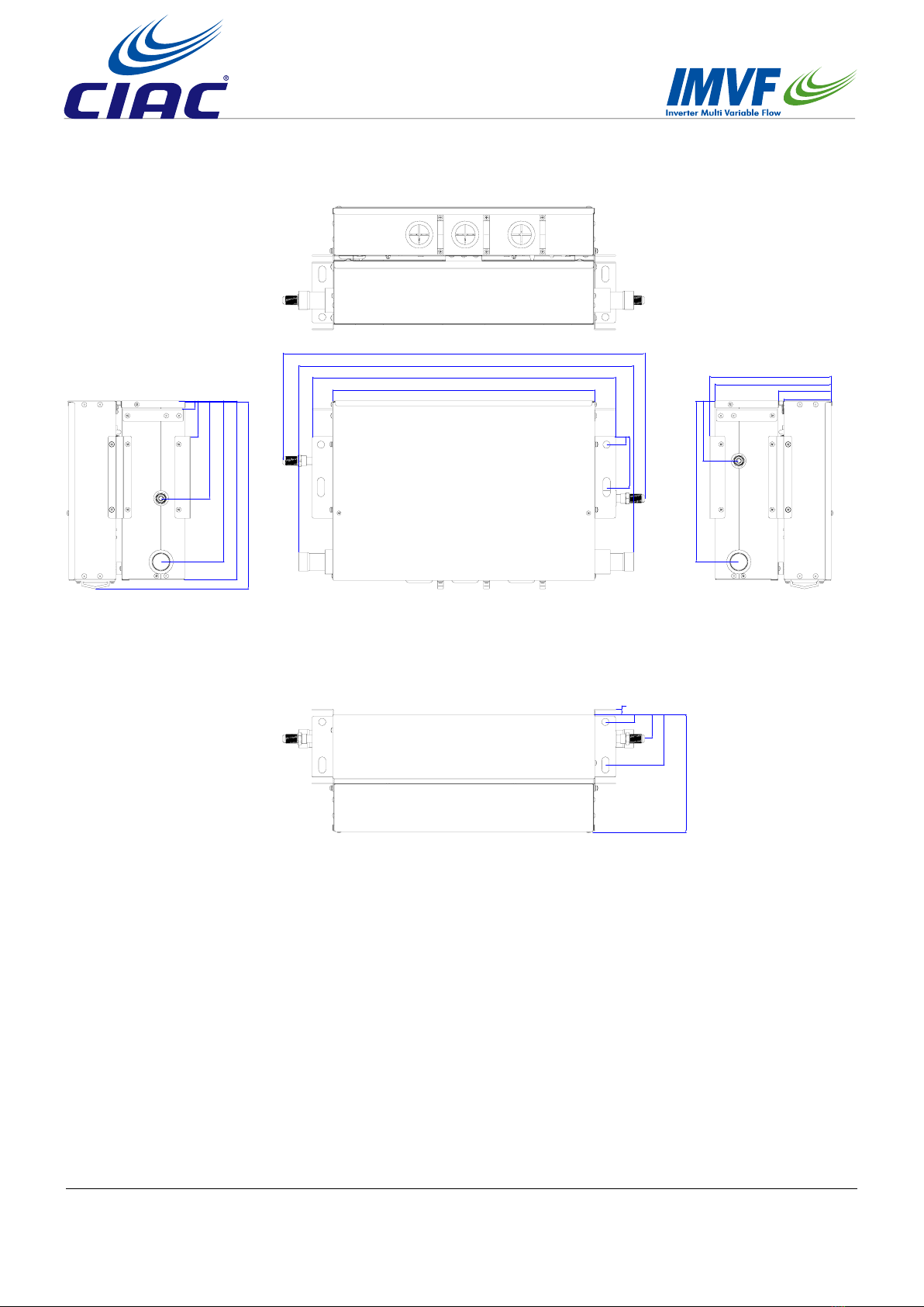
5.4.2 Preparation before installation
(1) Connection kit dimension (mm)
Max 5000
Electrical box Connection kit
Dividually mounted (mm)
AH1-280A
147
226
163
195
80
476
419
350
15
(2) Lifting dimension of connection kit (mm)
AH1-280A
AH1-560A
37
71
AH1-560A
161
296
201
99
266
597
553
433
385
70
389
467
70
472
Fig.1
16
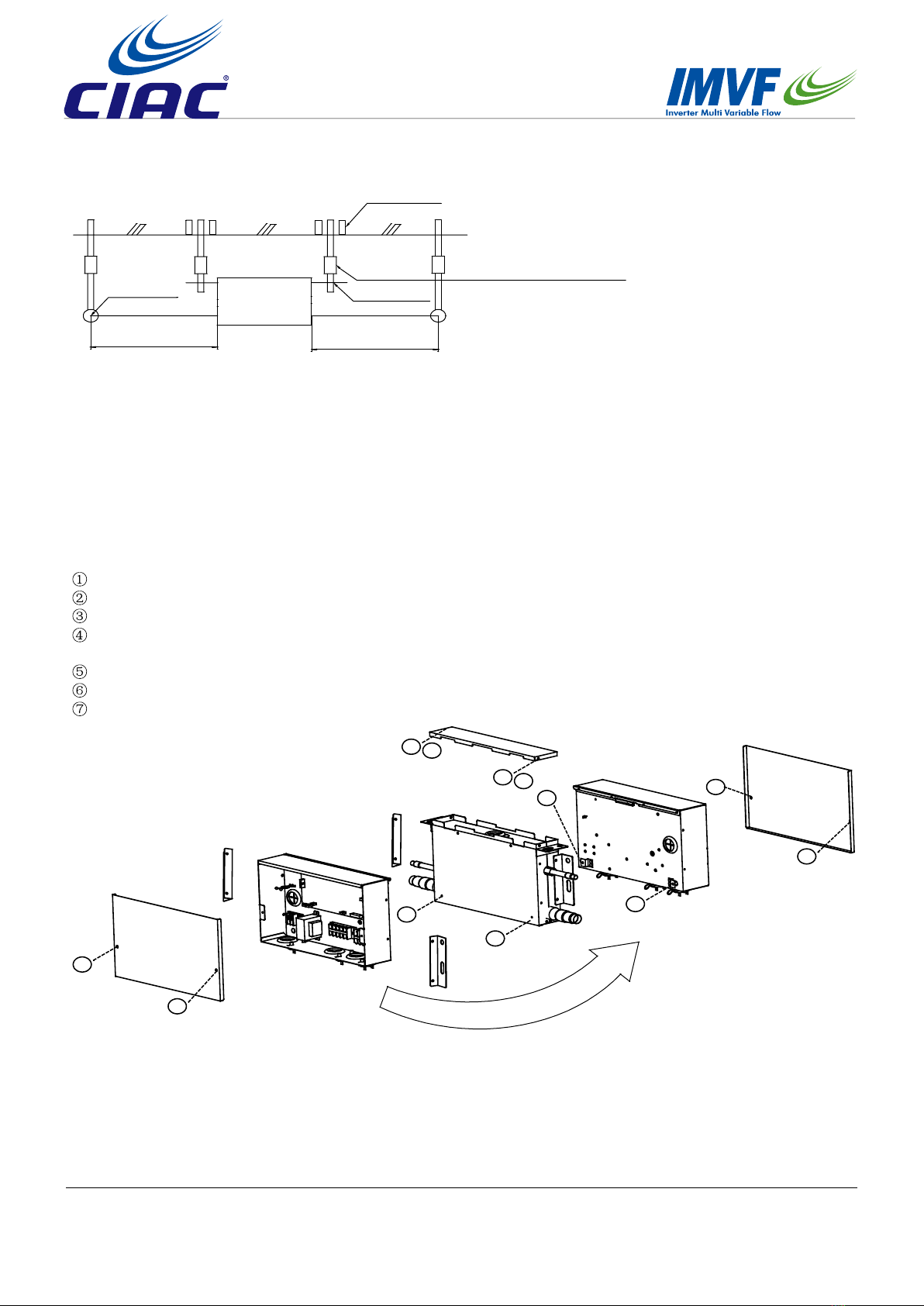
5.4.3 Installation of connection kit
Use parts and components specied for installing the installation components.
(1) Change the installation direction of electric box according to requirements following the steps below; (see
Fig.1)
Remove the cover of the electrical appliance box; (2 screws)
Remove the electrical appliance box; (2 screws)
Remove the top plate; (4 screws)
Change the outgoing direction of wiring (electric valve coil) between the equipment and the electrical appliance
box;
Rotate 180° to install the top plate;
Install the electrical appliance box;
Install the cover of the electrical appliance box.
Fig.1
④Electrical appliance removal
1
1
3
3
2
2
5
5
7
7
6
6
Thick cement plate
Foundation bolt
Long nuts or turnbuckle
Lifting bolt
Connection
kit
Lifting tools
Less than 1m Less than 1m Note: All the parts in the gure are purchased locally.
See the Fig.1 & Fig.2 to install the lifting bolts and hoisting tools.
• Use the lifting bolts with the size of M8~M10
• Press insert for new settings. Press hole in anchor if set. Ensure that it can sufciently withstand the weight of
the connection kit before installation.
Fig.2
17
5.4.4 Refrigerant pipe Installation
• Pipes between the outdoor unit and connection kit, selection of refrigerant branching suite, and the Pipe between
refrigerant branching suites and the indoor units, please refer to the installation instructions or equipment design
data attached to the outdoor unit.
• Before Installation, make sure the type of the refrigerant to be used is R410A. (If a refrigerant other than this type
is used, It cannot run properly)
• Please provide thermal insulation at the high-pressure gas pipe, suction gas pipe,, liquid pipe and oil equalizing
pipe (pipes for outdoor units in case of multi-split system) and the connections between these pipes. In the
absence of thermal insulation, liquid leakage and scalding may happen. Particularly when the high-pressure
gas pipe delivers indrawn air under full-refrigeration condition, it needs the same thermal insulation as does the
suction gas pipe. Besides, high-pressure gas pipe and suction gas pipe are to deliver high-pressure gas, thus
please provide thermal insulation material that can sustain temperature over 120 °C.
• Enhance the thermal insulation material based on the installation environment. The indicators are shown below.
For RH75%–80% at 30°C: over 15 mm thick.
For over 80% at 30°C: over 20 mm thick.
If not reinforced, the thermal insulation material surface is prone to condensation. Please refer to the equipment
design data for further details.
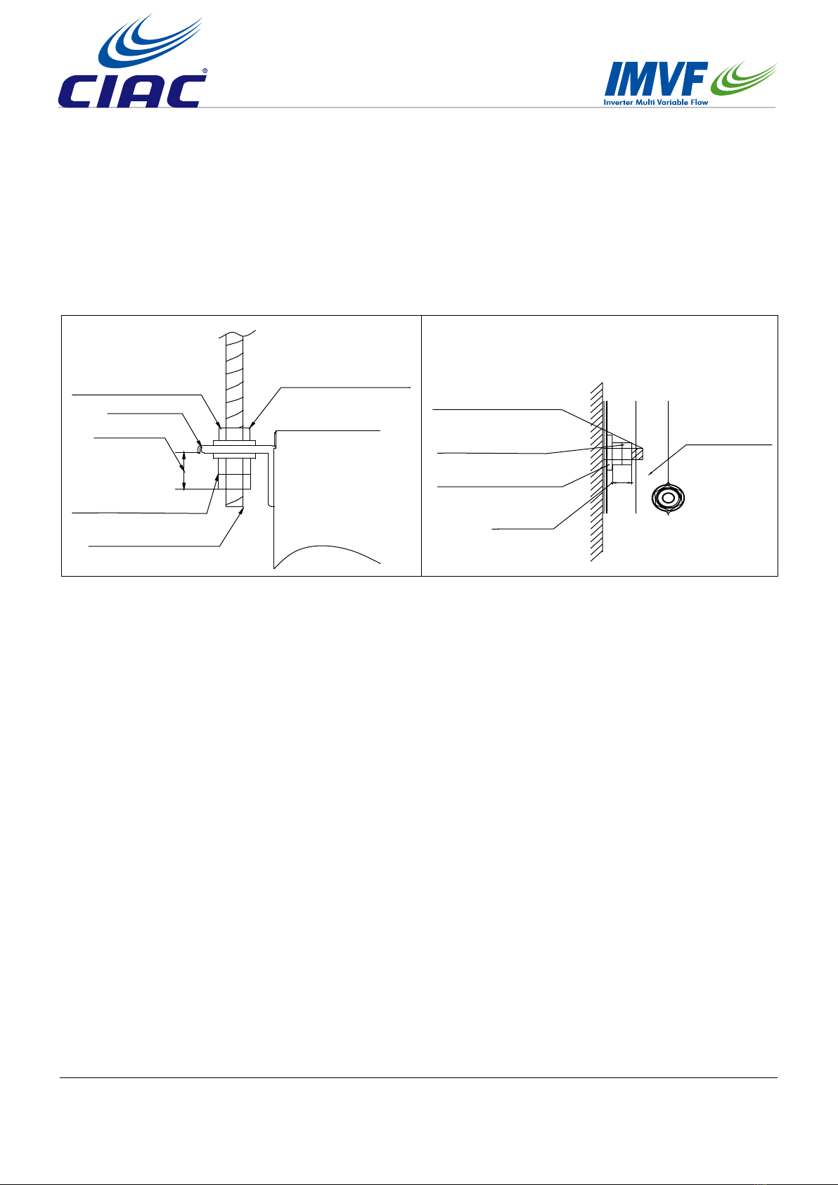
Fig.2
Wall mounted
Gasket
(purchased locally)
Double nuts
(purchased locally)
Lifting bolt
(purchased locally)
Nut
(purchased locally)
Connection kit
10-15mm
Lifting tool
Lifting bolt
(purchased locally)
Double nuts
(purchased locally)
Gasket
(purchased locally)
10-15mm
Connection kit
Ceiling mounted
Install the lifting tools on the lifting bolts according to the instruction of the Fig.2
Be sure to follow the stipulations on products locally purchased to use nuts (M8 or M10 of 3 pieces for 4 positions)
and gaskets (M8 with the outer diameter of 24~28 mm and M10 with that of 30~34 mm of 2 pieces for 4 positions)
on the upper and lower sides of the lifting tools.
<Note>
Be sure that the product must be installed with the top surface (the oblique surface in the Fig.2) upward, or it will
not work well and increase the working noise.
18
<Notes>
• Please do not let any type of gas other than the specied refrigerant go into the refrigeration system;
• In case of refrigerant leakage during operation, please replace the gas. (Fill the refrigerant at the outdoor unit)
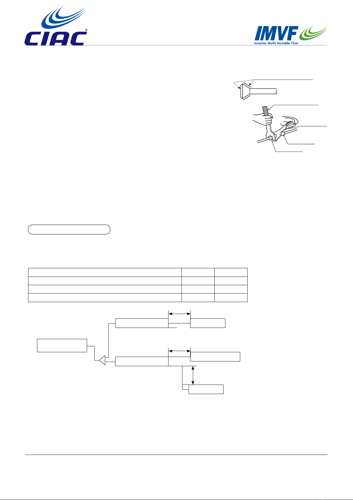
Paste the refrigerant oil here
Torque spanner
Spanner
Pipe joint
Cone nut
Fig.1
Select piping material
• Make sure both the internal surface and external surface of the pipes are intact and are free from harmful
contaminants such as sulphur, oxide, foreign matter, cutting powder, grease and water.
• Please use the following materials for refrigerant pipe.
connection kit AH1-280A AH1-560A
Connection kit-indoor max. single pipe length /m 5 5
Connection kit- indoor max. drop /m 5 5
Connection kit- electrical box max. distance 5 5
• The branching pipe for the pipe must have refrigerant branching suite. For selection of refrigerant branching
suite and max. height drop between indoor units, please refer to the installation instructions or technical data
attached to the outdoor unit.
Outdoor
Connection Kit
Connection Kit
Indoor
Electrical box
Max. length 5m
Max. length 5m
The high-pressure gas pipe, suction gas pipe, liquid pipe must be provided
with reliable thermal insulation. In the absence of thermal insulation, liquid
leakage may happen.
The outdoor unit is already lled with refrigerant.
To connect the pipes to connection kit or remove them from connection kit,
do use both spanner and torque wrench, as shown in the Fig.1.
Apply refrigerant oil to inside and outside of the are. Screw it for 3 to 4
rounds with hands and then tighten it.
Determine the tightening torque. (Excessive tightening may damage the nuts
and hence cause leakage)
Check the connecting pipes for gas leakage and then x the thermal
insulation, as shown in the in the Fig.2
Only use sealing gasket to wrap the part jointing between the gas pipe and
thermal insulation.
For pipe cutter and are tool, please use R410A special tools.
Indoor
Max. height drop 5m
This manual suits for next models
4
Table of contents
Popular Fan manuals by other brands

Maico
Maico ECA 120 SERIES Mounting and operating instructions

Makita
Makita CLX303 owner's manual

U.S. FAN
U.S. FAN UVQL900 quick start guide

ARDES
ARDES AR5PR40PR2 Instructions for use

Ebmpapst
Ebmpapst W6E500-CJ03-81 operating instructions

MrCool
MrCool UNIVERSAL MDUCC150 Series Owners & installation manual


