VES Ecovent EVH Series Manual

VES Ref. ID.1425
May 2022
Original Instructions
Eagle Close, Chandlers Ford Industrial Estate, Chandlers Ford, Eastleigh, Hampshire, SO53 4NF
Tel: +44 (0) 2380 46 11 50 email: inf[email protected] web: www.ves.co.uk
Issue G
Operation & Maintenance Manual
®
Hybrid Ventilation Units

2
This manual must be read in full before Installation, Operation and Maintenance of the units supplied
Please ensure that this document is passed to the end user. This manual forms an integral part of
the product and should be kept for the working life of the product. Additional copies of this and
supporting documents are available by contacting VES or by visiting www.ves.co.uk and following
the 'Download O & M's' link.
The following symbols used within this document refer to potential dangers, advice for safe
operation or important points of reference
Indicates hazards associated with electric current and high voltages
Indicates hazards that require safety advice for personnel or potential unit/property damage
Indicates important information
Warning
Caution
Important
Important
Conventions
ecovent Hybrid Ventilation Units
page
Introducon .................................................................................................................................. 2
Nomenclature ................................................................................................................................ 3
Receipt of Goods & Handling ........................................................................................................ 4
Installaon ......................................................................................................................................4
Standard Wiring & Fan Installaon .......................................................................................... 8
Maintenance .............................................................................................................................. 14
1
2
3
4
5
6
Contents
Introducon 1 Ecovent® EVH is a range of hybrid venlaon units with opmised dues of 0.060, 0.128 and
0.256 m³/s. All units are available as a master/slave pair. Each unit is suitable for ceiling void,
plantroom or internal locaons only.
As standard, each unit will have been supplied either pre-wired to a fied control panel or prewired
fied isolator, as specified at the me of order. The standard operang temperature of these units is
-20 to +35 °C.
For further technical details regarding dimensions and weights, contact VES on 023 8046 1150,
quong the sales order (SO) number and the unit type as found on the unit nameplate, or
alternavely visit www.ves.co.uk.

3
ecovent Hybrid Ventilation Units
Nomenclature
Part Number Coding
Point Descripon Point Variants Details (as appropriate)
1 Product EV Ecovent® Acousc Heat Recovery Units
2 Heat Recovery type HHybrid Venlaon Unit
3 Unit Size 0, 1, 2 Sequenal see unit outline for details
4 Fan Type 7Centrifugal EC fan
5 Fan Size 4Sequenal
6 Phase -1 230V 50Hz Single Phase
7 Main Heang Null No Heang
-CW Chilled Water Coil
-W LPHW Coil
8Casework Lining Null Standard
/A1 Variant (sequenal)
9 Handing /LB Le/Bottom Access
/RB Right/Boom Access
10 Main Filter Null No filter
11 Control Panel Secon
/MS01
/SV01
14 Colour Null Galvanised finish
/R9010 RAL Colour as specified
15 Finish MT Ma
SG Internal powdercoated only
FG Internal/External powdercoated
16 Special /S Special (non-standard) Unit
EVH174-1/RB/MS02/GL/R9010SG/0253
1 2 3 4 5 6 7 8 9 10 11 12 13 14 15
Typical Example
2
-E Electric Heater Baery
(looking in direcon of supply airflow)
Fied control panel (master) V1
Fied control panel (slave) V1
Null No controls
/MS02
/SV02
Fied control panel (master) V2
Fied control panel (slave) V2
13 Gas Proving System
Null
/EM
No system
/GF
/GM
Gas Proving System (Flamefast)
Gas Proving System (Merlin)
12 Energy Monitoring
Null No system
Energy Monitoring
FG Leatheree
EV H 1 7 4 -1 /RB /MS02 /GL /R9010 SG /0253
16

4
ecovent Hybrid Ventilation Units
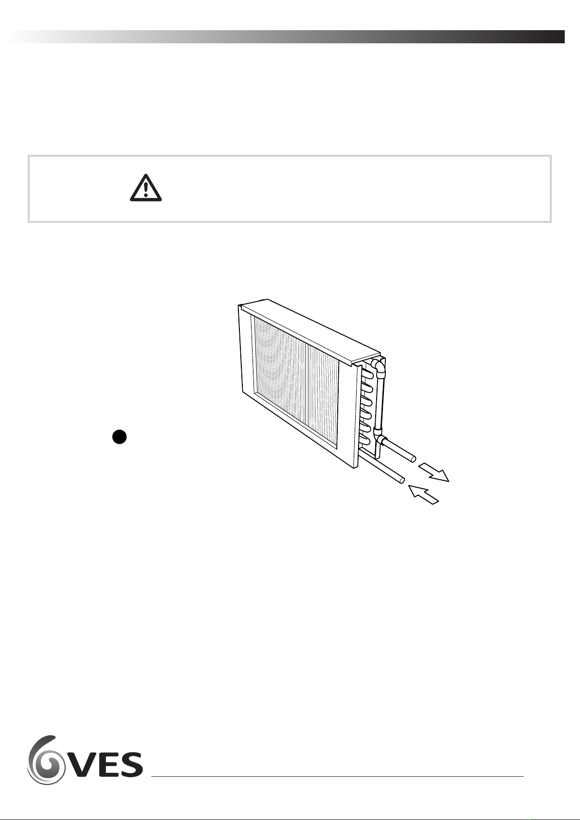
Immediately upon receipt of goods, check for possible damage in transit paying parcular
aenon to fan impellers, coil connecons and unit casing. Prior to installaon please check to
ensure alignment and smooth rotaon of the impeller aer transit. Also check to ensure that
any ancillary items are included. These will normally be supplied fitted or, in the case of small
items, taped to the unit.
In the event of any damage having occurred or if any item is found to be missing, it is essenal
to inform VES Andover Ltd. within 7 days of delivery quong sales order number and the unit
type, as found on the unit nameplate. Aer this period, VES is unable to accept any claim for
damaged or missing goods.
The enre system must be considered for safety purposes. It is the responsibility of the
installer to ensure that all of the equipment is installed in compliance with the manufacturer’s
recommendaons, with due regard to the current HEALTH AND SAFETY AT WORK ACT and
conforms to all relevant statutory regulaons.
Where a unit is installed such that component failure could result in injury to personnel,
precauons should be taken to prevent such an injury. If the unit is installed where there is a
reasonable possibility of persons or objects coming into contact with the impeller whilst
operaonal, a guard should be fitted or steps taken to prevent this. It is the installer’s
responsibility to ensure that access panels are not obstructed in any way. Safe working access
for maintenance must be provided in accordance with Health and Safety and Building
Regulaons. For confirmaon of required access please see the appropriate unit outline
drawing.
For safe maintenance, consideraon must also be given by the installer for adequate
illuminaon of the unit locaon. Further consideraon should be given to the unit’s posion
and secured into place as appropriate.
Mounng hangers, door furniture, isolators etc. extend beyond the casework, so are vulnerable
to accidental damage. Take necessary precauons so as not to cause damage whilste handling
the unit.
The weight of each unit/secon is specified on the outline drawing and the total unit weight will
be displayed on the unit inspecon label. When liing the unit using a fork li truck ensure the
whole unit is supported by the full length of the forks. It may be necessary to use fork extensions
to fully support the unit. The centre of gravity may be offset from the centre of the unit; this
needs to be taken into consideraon when liing the unit.
Handle with care. Failure to fully support the unit during liing may result in damage to the
unit casework
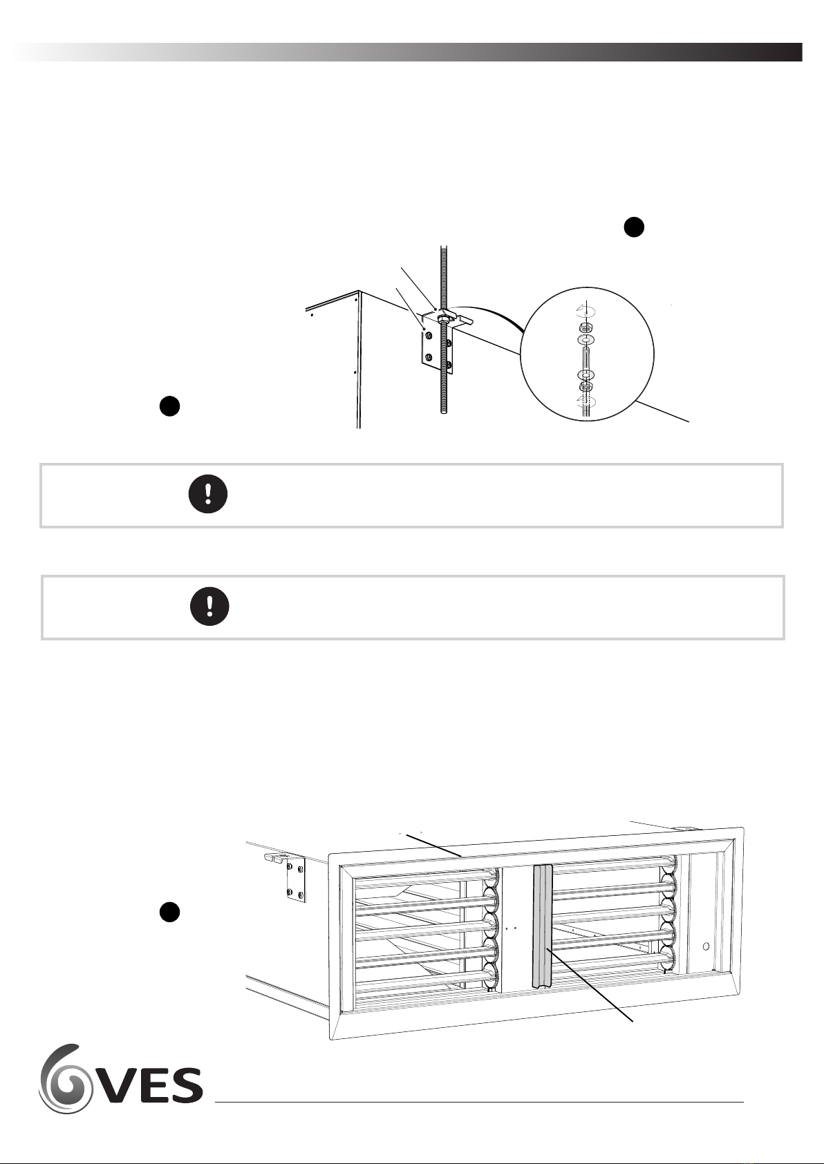
Units are to be rigged and lied using spreaders, taking
into account the weight of the unit. Liing gear should
be arranged so as not to bear on the casework, see right.
Cauon
Receipt of Goods
and Handling
Installaon
3
Liing Detail
Fig. 2
4
Cauon
Fork Liing Detail
Fig. 1

5
ecovent Hybrid Ventilation Units
Connued
Ecovent® EVH units are supplied with hangers suitable for drop-rod or ceiling-void mounng,
in boom access orientaon, with airflow in the horizontal plane.
For alternave mounng please consult your outline drawing as supplied with the unit, or refer
to VES Customer Services for further informaon.
Secure drop rods/unit with the appropriate fixings as shown below .
When hanging units from drop-rods, ensure that the load is evenly spread and that ALL
brackets are used within the support. Ensure that the drop rod/fixing used is selected
appropriately to accommodate the load of the unit.
Unit mounng detail
Fig. 3
Installaon 4
Important
Ecovent® EVH units are intended to be connected to a wall or window-mounted louvre. This can be
a direct connecon (from unit to louvre) or via a specific transion duct.
In situaons where access to the outside grille for cleaning is limited, provision should be
made for suitable access from inside the building. This is parcularly relevant for installaons
with long transions where it would be difficult to reach the grille from inside the hybrid unit.
To ensure the opposing supply and exhaust airflows are separate, a site-specific splitter MUST be
incorporated into the installaon (supplied by others). This can be incorporated into the wall
cavity, transion duct or external louvre, depending upon the exact site requirements. A 30mm
wide splier channel posioned centrally on the unit has been incorporated into the unit to assist
with alignment. This is removable if not required.
For units mounted flush against wall openings, a finishing flange is available to assist with this.
Ensure that the joint between unit and wall is sealed correctly. The flange is handed; ensure the
widest part is toward the boom of the unit see fig.
Finishing Flange &
Splier arrangement
detail
Fig. 4
3
Bracket Fixings
Finishing
Flange
Moun!ng Bracket
Mounng Bracket
Bracket Fixings
Finishing Flange
(Loose)
Splier Channel
Important

6
ecovent Hybrid Ventilation Units
Connued
Duct transions and plenum boxes allow for resizing and/or realignment as required and
should be sized to match both unit and louvre connecons. A pair of joining brackets per
secon (one each side) are provided to assist with the duct connecon.
The example shown in fig. below depicts a two-part transion/plenum, each secon having
its own set of joining brackets.
Fix the bracket parts to both sides of unit and transion as shown using the M6 fixings
provided. Tape the joint using self-adhesive rubber tape prior to assembly to prevent air
leakage.
To finish the assembly, bring the secons together and install the M8 joint fixings through both
parts of each joining bracket and ghten using a 6mm hex key, drawing the secons together
evenly, ensuring no visible gaps.
The nut is loose but held within the bracket body. Take care not to dislodge when fixing.
Installaon 4
Cauon Flange connecons and channels are NOT structural and are included as part of the unit
sealing only. When moving assembled units ensure that ALL secons are fully supported.
Typical transion
assembly detail
Fig. 6
6
Important
Splier
Splier
Channel
Typical installaon
detail (plan view)
Fig. 5
Window/
Louvre

7
ecovent Hybrid Ventilation Units
Typical LPHW Coil
Fig. 7
Connued
Installaon 4
Coils should be piped according to any relevant local codes of pracce. As standard EVH coils are
supplied with a Ø15mm plain stub suitable for push-fit connecons. All external piping is to be
supported independently from the coil. The flow connecon is nearest the boom of the unit (see
below)
It is important that coils are protected against damage from extreme weather condions during
the winter season. If the water is allowed to freeze in the coil system,
damage may occur potenally bursng pipes and resulng in emergency problems.
EVH LPHW units are fied with a coil temperature sensor as standard, ensuring that boilers run
connuously in low ambient temperatures can help to prevent damage.
On Ecovent® EVH/ -W units, a Low Pressure Hot Water (LPHW) coil will be installed. The coils are
normally suitable for low pressure hot water with a range of between 80 ~ 40 °C flow and between
70 ~ 30 °C return temperature. The coil should be regularly vented so as to avoid potenal air
locks, resulng in a fall off of duty.
Cauon
It is recommended that a check be made as to whether any treatment is required to the water
supply for prevenon of corrosion and scaling of the equipment. Informaon regarding the
necessary acon to be taken can be obtained from the relevant Local Water Supply Authority.
The unit will have been supplied with connecons either le or right-hand side looking in
direcon of airflow. Please see order acknowledgement for confirmaon of this handing.
Should you need to alter this please consult VES as unit adjustment may invalidate your
warranty.
Flow
Return

8
ecovent Hybrid Ventilation Units
The electrical supply must be fully isolated before aempng to affect any work on this unit.
All electrical connecons to any unit must be carried out in accordance with the current edion
of the I.E.T Regulaons, only competent Electricians should be allowed to affect any electrical
work to our units.
A cable entry point is provided at the control secon.
It is the responsibility of the installer to ensure that a suitable cable gland (giving adequate
protecon and strain relief) is fitted, and in doing so also ensure that no internal components
are damaged during this installaon. Make certain all swarf is removed before use.
It is the customer’s responsibility to supply earth fault protecon through the building
installaon device and a dedicated, isolated power supply with overload protecon, to account
for motor start up currents.
Do not connect any unit to an electrical supply voltage outside of the specificaon.
The following wiring diagrams are a guide to installing the standard fan and actuator opons
found on Ecovent® EVH units. If in any doubt, for units with fied VES controls or for special
versions of the units, consult the wiring diagram in your document pack or contact VES
Customer Services on 023 8046 1150, quong the sales order (SO) number and unit type as
found on the unit name plate.
For incorrect fan rotaon, check with the VES Customer Services for advice, on 023 8046 1150.
Standard Wiring
and Fan Installaon
5
Warning
Important
Warning
Standard Fan Details
Fig. 8

9
ecovent Hybrid Ventilation Units
Standard Wiring
& Fan Installaon
5Connued
Standard Controls
(Master)
arrangement
Fig. 9
8
ventilation control
á2°C
â2°C pause
boost
Connecon to
Modbus/Bacnet MS/TP

10
ecovent Hybrid Ventilation Units
Standard Wiring
& Fan Installaon
5Connued
Standard Isolator
(Slave)
arrangement
Fig. 10
8

11
ecovent Hybrid Ventilation Units
Important The following gives an overview of the current and previous versions of Room override panel.
For details regarding its full operaon and the full controls philosophy, please contact
VES Controls Department on 08448 15 60 60 for further informaon
Standard Wiring
& Fan Installaon
5Connued
ventilation control
á2°C
â2°C pause
boost
Controls arrangement
2022
For each room an informaon and override panel is provided to allow the user to
override the automac controls.
The panel comprises:
• Fresh Air Boost switch
• Pause switch
•
Open windows indicaon
•
Temperature Adjustment switches o o
#2 C/$2 C
o o
When the #2 C buon is momentarily pressed the set point will be increased by 2 C. Pressing the
o
$2 C buon will cancel this acon.
o o
Likewise, when the $2 C buon is momentarily pressed the set point will be decreased by 2 C
o
If the unit is in heang mode, when the #2 C buon is pressed for 3 seconds the unit will go into
Heang Boost.
Operaon of the boost switch will start the system (if off) in fresh air boost mode and the boost LED
will illuminate. The fans will run at “Boost Switch Supply Speed”. The mixing box posion will be
limited to force fresh air intake as shown in Secon 7. The system will revert to automac operaon
aer a pre-set period “Boost Switch Duraon” or if the switch is pressed again. A short me delay
will prevent rapid mode switching by unauthorised operaves.
Operaon of the Boost switch will run the unit to maximum set speed and modulate the dampers
to allow maximum amount of fresh air possible without affecng room temperature. If the unit is
off, operaon of the Boost switch will start the system in boost mode. The system will revert to
automac operaon aer a preset period or if the switch is operated again. A me delay will
prevent rapid mode switching by unauthorised operaves.
Temperature Adjustment
Switches
Fresh Air Boost Switch
Override Panel
Fig. 11
EPEL3001
Override Panel
o
#2 C Buon
o
$2 C Buon
Boost Buon
Pause Buon
Open Window Indicaon

12
ecovent Hybrid Ventilation Units
Operaon of the Pause switch will pause the system. The system will revert to automac operaon
aer a preset period or if the switch is operated again. A me delay will prevent rapid mode
switching by unauthorised operaves.
The open windows indicaon shall illuminate when the external temperature reaches a suitable
level to encourage manual window opening. The centre LED will illuminate if the external
temperature exceeds “Window Open Minimum External Temperature” (default maximum 5°C
between the room setpoint and external air temperature).
Alternavely, the LED will illuminate if the room CO level exceeds the CO Setpoint” to encourage
2 2
manual opening of the windows to assist the unit in achieving target condions.
Diagnosc mode is used to give a simple indicaon of any alarms that may be present in the
system. Further examinaon can be made via connecons with the BMS or through a handheld
HMI.
If the Boost and Pause switches are pressed together and held down for three seconds the
teachers panel will temporarily enter a diagnosc mode. All the LEDs on the teacher panel will flash
up together to show that the panel has entered diagnosc mode. 10 seconds later all the LEDs on
the teacher panel will again flash up together to show that the panel has exited diagnosc mode.
In diagnosc mode specific alarms are indicated by the following LED sequences:
Pause Switch
Standard Wiring
& Fan Installaon
5Connued
Open Windows Indicaon
Diagnosc Mode
Diagnosc Mode
Fig. 12
When in diagnosc mode if the Boost switch is pressed, all present alarms will be acknowledged.
Important

Standard Wiring
& Fan Installaon
5
Controls arrangement
Pre 2022
Override Panels
Fig. 13
Connued
For each room an informaon and override panel is provided to allow the user to
override the automac controls.
The panel comprises:
• Boost/Pause switch
• Boost/System Healthy acve indicaon
• Open windows indicaon
•Oponal+/- 2 °C Temperature trim switch
Operaon of the Boost switch will run the unit to maximum set speed and modulate the
dampers to allow maximum amount of fresh air possible without affecng room
temperature. If the unit is off, operaon of the Boost switch will start the system in
boost mode. The system will revert to automac operaon aer a preset period or if the
switch is operated again. A me delay will prevent rapid mode switching by
unauthorised operaves. The Boost/System Healthy indicaon will illuminate with an
asymmetric pulse.
Operaon of the Pause switch will pause the system. The system will revert to automac
operaon aer a preset period or if the switch is operated again. A me delay will
prevent rapid mode switching by unauthorised operaves. The Boost/System Healthy
indicaon will stop illuminang unl the unit resumes normal operaon.
The Open windows indicaon shall illuminate when the external temperature reaches a
suitable level to encourage manual window opening. The preset temperature for
indicaon shall be set through the BMS at 15° C such that should the windows be
opened, there will never be a temperature differenal of more than 5° C between room
design temperature and incoming fresh air.
An oponal secondary condion can be acvated to enable the window open indicaon
if the CO2 level in the classroom reaches 1500 ppm. In this case, the window open
indicaon will be illuminated.
EPEL2008 has the same funconality and characteriscs as the above with the addion
of the +/-2°C Temperature trim switch, which provides user override of room design
temperature by +2°C or -2°C. This is limited to 2°C either side of the setpoint, the system
will revert to automac operaon aer a preset period.
For details regarding older switchplate designs or special versions please contact VES
Customer Services on 023 8046 1150 for further informaon.
The system healthy indicator will illuminate when the unit is operaonal. In the event of
a system failure, the indicator will be off and the buons will be unresponsive e.g
pressing the boost buon results in no boost indicaon. Should this situaon arise the
system should be checked for a possible fault.
EPEL2008
Override Panel c/w temperature trim
EPEL2009
Override Panel (no trim)
Important
13
ecovent Hybrid Ventilation Units

14
ecovent Hybrid Ventilation Units
Maintenance 6
Before aempng to carry out any work on VES units, all accompanying documentaon
including warning labels on the unit must be referenced.
Should it be necessary to remove any component, ensure they are secured into posion once
reinstalled. It is crical that aer any maintenance work has been conducted that all
components removed/replaced be refitted correctly by a competent engineer.
Before aempng to carry out any maintenance work, invesgave or repair work on our
units, the unit MUST BE COMPLETELY ISOLATED from its electrical supply. Ensure a minimum
of two minutes aer electrical disconnecon before removing access panels. This will allow
any moving parts to come to a complete standsll.
Care should also be taken when accessing external units as the wind and elements may cause
moving parts to ‘windmill’.
In general, this series of units require lile maintenance. In the unlikely event of component
failure, spares are available from stock at VES Andover Ltd.
When accessing the unit ensure the access panels are handled/opened in a controlled manner
so as to avoid damage to the unit or injury to personnel. This is parcularly important with
boom access units. Ensure the AHU has come to a complete stop before aempng any work
on the unit
Ecovent® EVH units feature plug & socket connecons to allow easy removal/replacement of
key components. Separate the plug connecon by hand (tools not required) by pressing the top/
boom clasp mechanism to open and pulling the plug/socket apart .
DO NOT pull the cables to separate the assembly .
Plug & socket operaon
Fig.
14
14 15
15
15
Important
Warning
Cauon
Important
On reconnecon, the assembly features a locang lug to ensure correct orientaon. Once
rejoined, lock the connecon together again using the corresponding system as shown.
Note the plugs are handed and forcing an incorrect connecon may result in damage to the plug.
Cauon To separate the assembly, hold the plugs to pull them apart. DO NOT pull the cables.

15
ecovent Hybrid Ventilation Units
Maintenance 6
Important
Connued
Ecovent® EVH units feature bulkhead-mounted fan plate assemblies.
Ensure that special care is taken when removing/replacing components/assemblies from
boom-access units. Larger access panels may require the use of two or more persons.
THE CONTROL ACCESS COVER MUST BE REMOVED BEFORE THE UNIT ACCESS COVER to gain safe
access to the unit. Ensure all panels are safely replaced aer access.
Supply Fan assembly
removal/installaon
Fig. 17
Ecovent® EVH units feature double inlet centrifugal fans mounted on an adapter plate.
The supply fans are clearly visible beneath the main access panel.
To remove/replace, unplug as per Fig. , undo the fixing screws and carefully remove the
fan/adapter plate assembly, retaining all fixings.
To replace the fan assembly, secure one fixing leaving enough of a gap to allow the adapter
plate to slide into place. Fit the remaining fixing and ghten both. Ensure the impeller is free
running. Reconnect the supply plugs as in Fig. ; if more than one plug is used, ensure the
correct plugs are reconnected as marked.
The fan mounng plates are sloed to aid plate alignment. It is important to keep the fan
assembly supported at all mes; the fan assembly should not be considered supported unl
all fixings are securely ghtened.
Important
EVH1
Key components
Fig.16
14 15
14 15

16
ecovent Hybrid Ventilation Units
Maintenance 6 Connued
It is common for the external louvre on the outside of the building to feature a mesh which over
me can become blocked with leaves and other detritus. It will be necessary to clean the louvre
periodically or the venlaon unit may perform poorly.
This maintenance can normally be carried out from the outside of the building however should
it be necessary, some limited access might be possible from the inside of the hybrid unit,
through the blades of the fresh air inlet damper.
To gain access:
• Remove both the bottom and control cover.
• If required refer to page 12 for fan removal.
• The fresh air damper actuator (examples of which are shown below) features a clutch
release buon. Whilst engaging this buon turn the damper blades by hand to the open
posion. Take care whilst doing this as the button may be obscured.
When complete it is not necessary to close the damper blades.
During any maintenance take care not to damage any of the internal components
Important
Ensure that special care is taken when removing/replacing components/assemblies from
boom-access units. Larger access panels may require the use of two or more persons.
THE CONTROL ACCESS COVER MUST BE REMOVED BEFORE THE UNIT ACCESS COVER to gain safe
access to the unit. Ensure all panels are safely replaced aer access.
Before aempng to carry out any maintenance work, invesgave or repair work on our
units, the unit MUST BE COMPLETELY ISOLATED from its electrical supply. Ensure a minimum
of two minutes aer electrical disconnecon before removing access panels. This will allow
any moving parts to come to a complete standsll.
Care should also be taken when accessing external units as the wind and elements may cause
moving parts to ‘windmill’.
Warning
Manual Damper
Opening
Fig.
Important
18

Six Monthly Checks
Spares & Repairs
Recommended Checks
Connued
In order to keep the unit in good order the following maintenance roune is recommended:
The fan impeller should be cleaned every 6 months. Failure to clean the fan on a regular basis could
result in loss of fan performance, or cause it to fall out of balance. If a fan is staonary for long periods
in a humid atmosphere, it should be switched ON for minimum of two hours every month to remove
any moisture that may have condensed within the motor.
The fan motors are maintenance free due to the use of ball bearings with ‘life-long lubricaon’.
At the end of the grease life it may be necessary to change the fan unit.
Failure to keep dampers clean could result in the damper becoming inoperave. Clean damper
blades and frames and lubricate with PTFE aerosol or equivalent.
For units with integrated heang, the heang coil should be inspected for debris, dust or dirt build
up. If found contaminated, foreign maer should be removed accordingly; superficial dust or debris
can be removed from the surface of the heat exchange by gently brushing. Loosened debris can then
be vacuumed from the surface of the coil.
When enquiring aer or ordering spares contact VES Spares Department, quong the sales order (SO)
number and unit type as found on the unit nameplate.
Tel: 023 8046 1150
Maintenance 6
17
ecovent Hybrid Ventilation Units
At the end of their useful life the packaging and product should be disposed of via a suitable
recycling centre. Do not dispose of with normal household waste. Do not burn.
WEEE Direcve
PLEASE ENSURE THAT THIS DOCUMENT IS PASSED ON TO THE END USER

Eagle Close, Chandlers Ford Industrial Estate, Chandlers Ford, Eastleigh, Hampshire, SO53 4NF
Tel: +44 (0) 2380 46 11 50 email: inf[email protected] web: www.ves.co.uk
VES is a trading name of VES Andover Ltd.
Registered in England No. 02303719.
Registered Office as above.
©VES Andover Ltd. 2022
Operation & Maintenance Manual
®
Hybrid Ventilation Units
This manual suits for next models
3
Table of contents
Other VES Fan manuals

VES
VES MERA250 User manual

VES
VES POLO100 Series Instruction manual

VES
VES Colourfan CLE Series User manual

VES
VES Colourfan Series User manual

VES
VES Ecovent EVHR User manual

VES
VES AX315/4-1 Instruction manual

VES
VES ecovent EVH User manual

VES
VES VENA240 Instruction manual

VES
VES Short Case Axial series Instruction manual

VES
VES EURO100 User manual