manuals.online logo
Brands
  1. Home
  2. •
  3. Brands
  4. •
  5. CIE-Group
  6. •
  7. Amplifier
  8. •
  9. CIE-Group avid3 User manual

CIE-Group avid3 User manual

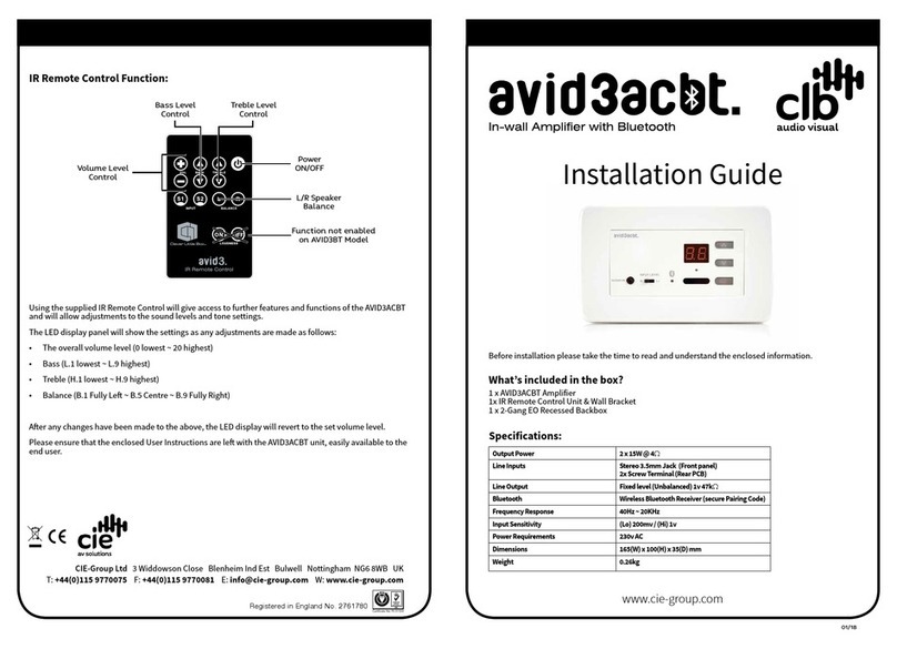
IR Remote Control Function:
Using the supplied IR Remote Control will give access to further features and functions of the AVID3 and
will allow adjustments to the sound levels and tone settings.
The LED display panel will show the settings as any adjustments are made as follows:
• The overall volume level (0 lowest ~ 20 highest)
• Bass (L.1 lowest ~ L.9 highest)
• Treble (H.1 lowest ~ H.9 highest)
• Balance (B.1 Fully Le ~ B.5 Centre ~ B.9 Fully Right)
Aer any changes have been made to the above, the LED display will revert to the set volume level.
Please ensure that the enclosed User Instructions are le with the AVID3 unit, easily available to the end
user.
Registered in England No. 2761780
CIE-Group Ltd 3 Widdowson Close Blenheim Ind Est Bulwell Nottingham NG6 8WB UK
T: +44(0)115 9770075 F: +44(0)115 9770081 E: [email protected]om W: www.cie-group.com
Bass Level
Control
Treble Level
Control
Volume Level
Control
Power
ON/OFF
L/R Speaker
Balance
Function not enabled
on AVID3BT Model
Before installation please take the time to read and understand the enclosed information.
What’s included in the box?
1x AVID3 Amplifier, 1x 24v DC 1.25A PSU, 1x IR Remote Control Unit and
1 x Wallmount Bracket for Remote Control.
Specifications:
Output Power 2 x 15W @ 4W
Line Inputs Stereo Phonos (L & R)
Stereo 3.5mm Jack
Screw Terminal (Rear PCB)
Line Output Fixed level (Unbalanced) 1v 47kW
Frequency Response 40Hz ~ 20KHz
Input Sensitivity (Lo) 200mv / (Hi) 1v
Power Requirements 24v DC, 1.25A
Dimensions 165(W) x 100(H) x 35(D) mm
Weight 0.26kg
Installation Guide
01/18
www.cie-group.com
Introduction:
Before installation please remove the Facia Trim Plate from around the front edge of the unit. This can be
refitted once the installation is finished and any decorating is completed.
The compact depth of the AVID3 unit will allow installation into standard UK 2-gang EO boxes, with a
minimum of 40mm depth.
These may be galvanised metal for installation in solid construction walls, plastic drylining (with lugs) or
may be installed into surface mounting Dado-type trunking systems using the appropriate fixings.
Front Panel Controls and Connectivity:
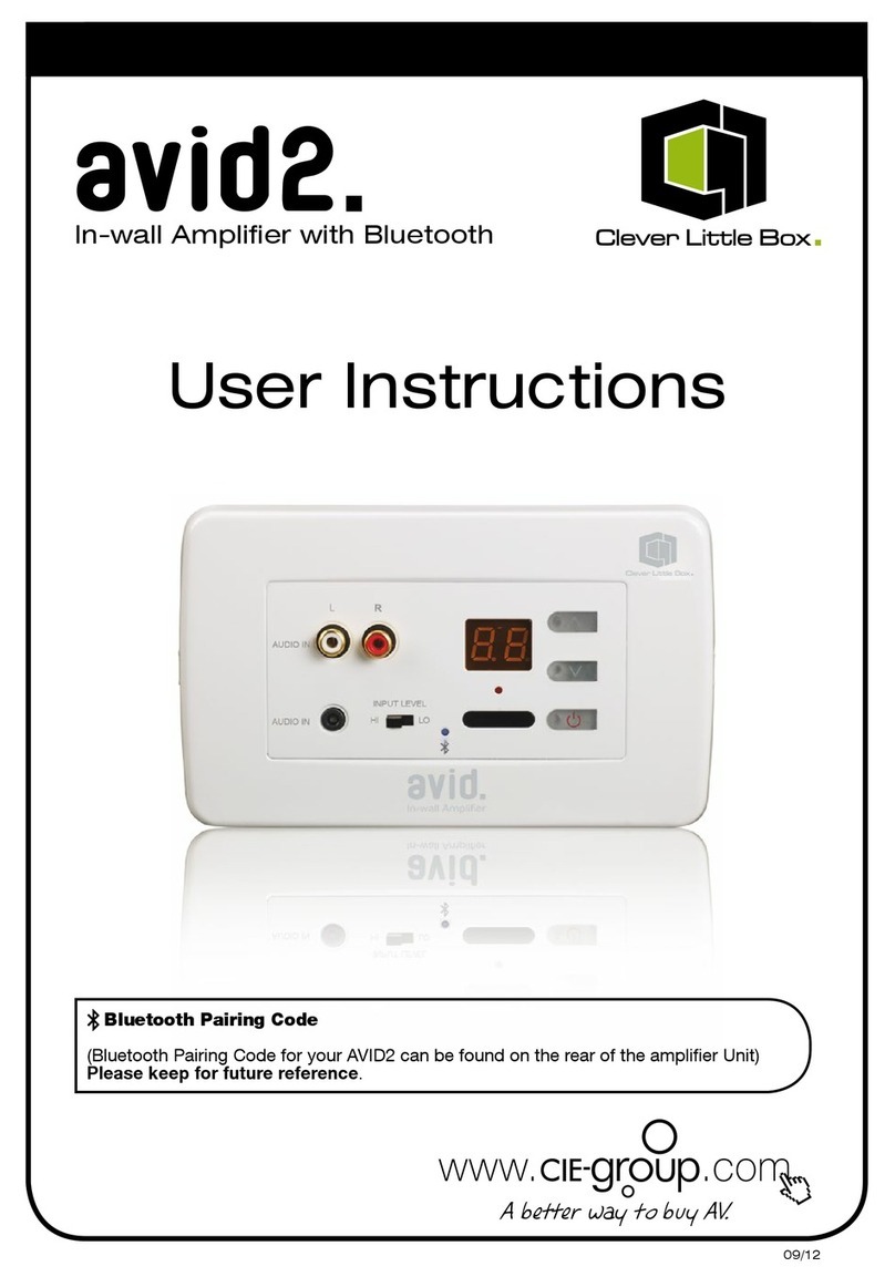
3 illuminated buttons allow basic control of the AVID3, the bottom button ( ) controls the ON/OFF
function, the up/down buttons ( ) control Volume Up and Volume Down.
Selection of which output is being broadcast is made by short pressing the ON/OFF Switch, S1/S2 is
displayed in the display to show which input is in use.
Two types of input are provided via the front panel; a Stereo 3.5mm Jack and Stereo Phono Inputs; and a
hard wired input is provided to the rear of the AVID3.
The Hi/Lo switch adjusts the input sensitivity from 1v (Line Level) to 200mv (average Headphone output
level), allowing the interface of generic MP3, CD and media players without loss of system volume level.
A clear LCD Display shows the desired volume level between 0 (no output) to 20 (maximum output) as well
as showing which input is in use (S1/S2).
Fascia
Trim
Plate
Hi/Lo Line
Level
Sensitivity
Switch
IR
Receiver
Window
Audio Level
Display
Volume
Level
Up
Volume
Level
Down
ON/OFF
Switch/
Input Select
3.5mm
Jack
Input
Rear Panel Controls and Connectivity:
Screw terminal connections for Power, Wired Input, Loudspeaker Outputs and Line Level outputs are
located on the rear PCB of the AVID3.
Power is provided via the included PSU; its cable being marked with a white line on the positive (+) core
which connects to the V+ terminal, the plain black core is negative (-) which connects to the G terminal.
The Wired Input terminal on the rear is configured for a Stereo Input Signal; the three-way connector has
terminals for L (Le Signal), G (Screen) and R (Right Signal).
Important Information:
It is important to note that if using the audio input loacated on the rear of the AVID3 that the signal
applied is at full line level.
When using this application an appropriate screened cable is required to reduce the possibility of external
signal interference.
Note. The Wired Input Terminal is in parallel with the 3.5mm Jack Input on the front panel; if both inputs
are connected and a signal is present on both, then the two sources will be mixed together (This should
be clearly explained to the user).
A jumper is provided to allow the AVID3 to be used in either mono or stereo mode, the factory default is
stereo. If set to mono the amplifier will provide a mixed output to each loudspeaker terminal.
Loudspeakers should be wired to the L+ L- and R+ R- terminals, ensuring the phase of each loudspeaker
is the same.
The line output is stereo and provides a fixed line output signal for feeding and external source such a s a
slave amplifier or induction loop system.
If you are experiencing any problems please contact your reseller or the CIE-Group Technical Support
Department on +44 (0)115 9770075.
Wired
Line Input
Connector
Power Supply Input
Connectors
Loudspeaker Output
Connectors
Loudspeaker Balance
Trim Pots
L+ L- R- R+
OUTPUT
AUDIO
INPUT
V+ G
Stereo
Jumper
Line Output
Connectors

Other CIE-Group Amplifier manuals

CIE-Group AVID3ACBT User manual

CIE-Group

CIE-Group AVID3ACBT User manual

CIE-Group TD 816 User manual

CIE-Group

CIE-Group TD 816 User manual

CIE-Group CLB-AVID User manual

CIE-Group

CIE-Group CLB-AVID User manual

CIE-Group AVID2 User manual

CIE-Group

CIE-Group AVID2 User manual

Popular Amplifier manuals by other brands

ORTEC 9305 Operating and service manual

ORTEC

ORTEC 9305 Operating and service manual

Marshall Amplification 1974X Brochure & specs

Marshall Amplification

Marshall Amplification 1974X Brochure & specs

DTC Audio Champ MP3-DVD user manual

DTC Audio

DTC Audio Champ MP3-DVD user manual

iSP g112 owner's manual

iSP

iSP g112 owner's manual

Bosch LBB 1914/10 Installation and operating manual

Bosch

Bosch LBB 1914/10 Installation and operating manual

Gec Plessey Semiconductors SL486 NA DP manual

Gec Plessey Semiconductors

Gec Plessey Semiconductors SL486 NA DP manual

Niles FG01703 installation guide

Niles

Niles FG01703 installation guide

Ashly Protea NE4250 Specification sheet

Ashly

Ashly Protea NE4250 Specification sheet

Sophia Electric 91-03 user manual

Sophia Electric

Sophia Electric 91-03 user manual

Tone King Ironman II Mini user manual

Tone King

Tone King Ironman II Mini user manual

Bogen PM-3000 Specifications

Bogen

Bogen PM-3000 Specifications

NAD PP-2 Specification sheet

NAD

NAD PP-2 Specification sheet

sparkfun HX711 manual

sparkfun

sparkfun HX711 manual

G-Wave BDA-PS7-2W-80-A Installation and operating manual

G-Wave

G-Wave BDA-PS7-2W-80-A Installation and operating manual

Cary Audio Design CAD-805AE owner's manual

Cary Audio Design

Cary Audio Design CAD-805AE owner's manual

Peavey VX 1.5 K operating guide

Peavey

Peavey VX 1.5 K operating guide

Basalte ASANO M3 installation manual

Basalte

Basalte ASANO M3 installation manual

Octava HDDA38 installation guide

Octava

Octava HDDA38 installation guide

manuals.online logo
manuals.online logoBrands
  • About & Mission
  • Contact us
  • Privacy Policy
  • Terms and Conditions

Copyright 2025 Manuals.Online. All Rights Reserved.