Cimon CIMON-NT Core 3000 Series User manual

www.cimon.com
User Manual
THIS DEVICE COMPLIES WITH PART 15 OF THE FCC RULES. OPERATION IS
SUBJECT TO THE FOLLOWING TWO CONDITIONS: (1) THIS DEVICE MAY NOT
CAUSE HARMFUL INTERFERENCE, AND (2) THIS DEVICE MUST ACCEPT ANY
INTERFERENCE RECEIVED, INCLUDING INTERFERENCE THAT MAY CAUSE
UNDESIRED OPERATION.
CIMON-NT(NP) Core 3/5/7000 Series

- 2 -
Touse this product correctly, it is absolutely required toread the
product descriptions before use.
1. For your safety and the safe operation of this product,
please read this manual before using the product. The
manual is subject to change without notice.
2. Please review the product specification in this manual to
determine the suitability of this product for its intended use.
3. For your safety, only qualified persons should perform
electrical and wiring attachments to this product.
FCC RF
INTERFERENCE STATEMENT
This equipment has been tested and found to comply with the limits for a Class A
digitaldevice, pursuant
to
part15oftheFCC Rules
. These limits are designed to
provide reasonable protection against
harmful interference when the
equipmentisoperatedina commercialenvironment.Thisequipment
generates,
uses, and can radiate radio frequency energy and, if the equipment is not
installed and used in accordance
with the instruction manual, it may cause
harmful interference to radio communications. Operation of
thisequipmentina
residentialareaislikelytocauseharmfulinterferenceinwhichcasetheuserwill
be
requiredtocorrecttheinterferenceathisownexpense.

- 3 -
Contents
Essential Safety Precautions ………………………………………… 4
General Safety Precautions ………………………………………… 7
UWF : Unified Write Filter …………………………………………… 8
Package Contents …………………………………………………… 9
1. Dimensions ……………………………………………………… 10
2. Interfaces ……………………………………………………………11
3. Installation ………………………………………………………… 15
4. Wiring & Power Supply Caution ………………………………… 17
5. Grounding Caution ……………………………..………………… 18
6. Specification …………………………………….…………………..19
7. Environmental Specifications …………………….………………. 20
8. Calibration Setting ………………………………………………… 21
9. Multi-Monitor Setting ……………………………..……………….. 23
Products Warranty ………………………………………………… 27

- 4 -
Precautions for design
•Do not draw a graphic object that can be hazardous to the operator or device. If
the product is damaged while output signal remain ON or OFF, fatal accident may
be caused. Design an emergency stop switch outside of the product so it can be
manually stopped.
•Do not use this product for the purpose of generating an alarm for injury to
operators. breakdown of devices, or production halt. Design the system so that is
can be hand-operated in case the product malfunctions.
•Do not use this product as a control unit on applications requiring extreme stability
such as airplane control device, aerospace device, centralized data processing
device, nuclear control system, medical life support system, etc.
•In case the product is used in transportation such as trains, vehicle, vessels, or
warning devices for disasters and crimes, various safety devices and medical
devices excluding life support system, you are required to design backup or failure
provision system to secure reliability and stability.
•Even if the screen is black, the unit could still be turned on with a dead LCD
backlight. When the operator touches a panel in this situation, the action could
cause device’s malfunction. Do not use product’s graphic object for controlling
safety devices such as emergency stop switches.
Essential Safety Precautions
WARNING

- 5 -
Prohibition of disassembly and modification
•Do not disassemble or modify the PC. It will void the warranty and may cause an
electric shock or fire.
Avoiding of flammable substances
• This version of the PC is not rated for flammable environments. Do not use this
panel around flammable gases. It may cause an explosion.
Precautions for installation
•Be sure to securely connect all cable connectors to the PC. A loose connection
may cause incorrect input or output.
•Make sure to tighten the screw with standard torque (0.5
–
0.6 Nm). Loose
connections may cause short, fire or malfunction.
•Be careful that metal debris does not enter the PC, they may cause a fire, panel
damage malfunction.
Precautions for wiring
• Make sure to check if the device’s power supply is turned off before wiring. Failure
to do so may cause electric shock or damage to the device.
• Do not use power beyond the specified voltage range of the PC. Doing so may
cause fire, electric shock or damage to the device.
Essential Safety Precautions
WARNING

- 6 -
• When grounding PC, make sure to separate it from other devices.
• If ground wires are close to each other, it may cause electric shock or damage to
the device.
• Use wire which has grounding resistance lower than 100 Ω and thicker than 1 mm2.
Follow your country’s applicable standard.
• Correctly wire the panel, be sure that the rated voltage and terminal layout are
within the designated range. If the voltage supplied differs from the rated voltage,
or incorrect wiring or grounding is performed,it may cause a fire or unit malfunction
and it will void the warranty.
How to manage LCD breakage
• LCD panel contains strong irritants. If you touch liquid of LCD due to its breakage
for any reason, flush your skin out for 15 minutes with the running water.
• If you get liquid of LCD in your eyes, flush your eyes out for 15 minutes with the
running water and contact a physician.
Maintenance –Battery Exchange
•The PC uses a lithium battery to back up the internal clock. Do not replace this
battery yourself because it may cause an explosion. If the battery needs to be
replaced, please contact your local service center.
Essential Safety Precautions
WARNING

- 7 -
• Do not strike the touch panel with a hard or pointed object, or press on the touch
panel with too much pressure, since it may damage the touch panel or the display.
• Do not install the PC where the ambient temperature exceeds the allowed range
(0
–
50℃). Doing so may cause the PC to malfunction or shorten product lifespan.
• Do not restrict or limit naturally occurring rear-face ventilation of the PC, or storing
or using the PC in an environment that is too hot.
• Do not use the PC in areas where large, sudden temperature changes can occur.
These changes can cause condensation to form inside the unit, possibly causing
the unit to malfunction.
• Do not allow water, liquids, metal or charged particles to enter the PC, since they
can cause either a PC malfunction or an electric shock.
• Do not store or use the PC in direct sunlight, or in excessively dusty or dirty
environments. Do not store or use the PC where strong jolting or excessive
vibration can occur.
• Do not store or use the PC where chemicals (such as organic solvents, etc.) and
acids can evaporate, or where chemicals and acids are present in the air.
• Do not use paint thinner or organic solvents to clean the PC.
•Do not store LCDpanel where the ambient temperature is lower than the its range
(-20℃
–
60℃). Doing so may cause congelation of liquid contained in LCD which
result in damage to the product.
•Do not store LCD panel where the ambient temperature is higher than the its
range (-20℃
–
60℃). Doing so may cause the liquid contained in LCD to become
isotropic and unreduced.
• After turning the PC OFF, be sure to wait 20 seconds before turning it ON again.
If the PC started too soon, it may not start up properly.
• Backup your PC project regularly to prepare for the unexpected accident.
• It is not recommended to update Windows by yourself. Please contact
manufacturer for Windows Update.
Precautions for unit disposal
•
When this unit is disposed of, it should be done according to your country’s
regulation for similar types of industrial waste.
General Safety Precautions

- 8 -
Supported OS
Windows 10 Enterprise, Windows 10 IoT Enterprise
C: drive of TOUCH/PPC is protected by UWF. UWF is a function of Windows
Embedded which protects the physical storage media from all write attempts.
• UWF intercepts all write attempts to a protected volume and redirects those write
attempts to a RAM.
• When TOUCH/PPC reboots, all data stored in the RAM are cleared. C: drive is
restored to the previous status.
• To enable/disable UWF, click [Start] and execute which is fixed on
the Start menu. Right-click on the program and run as administrator.
• When you click [Enable], the system reboots and UWF is enabled.
• When you click [Disable], the system reboots and UWF is disabled.
●To restore in Windows 10, run “UWF_SETUP_WIN8_WIN10” as
administrator and reset UWF, which is located in C:\XWF (or
C:\CIMON\XWFWin).
● If icon is deleted, run “XWFWin” in C:\XWF (or C:\CIMON\XWFWin).
● Professional OS(DSP) which is not ‘Embedded’, does not support
UWF.
UWF: Unified Write Filter

- 9 -
The following items are contained in the package of the PC series. Before using the
PC series, please confirm that all items listed below are present.
▪PC
▪Fastener
▪3PConnector ▪Installation Guide
This unit has been carefully packed, with special attention to quality.
However, should you find anything damaged or missing, please contact your local
CIMON distributor immediately.
Package Contents

- 10 -
Unit: mm
●
NTXX15 / NPXX15 (15 inch)
1. Dimensions
●
NTXX12 / NPXX12 (12 inch)

- 11 -
Unit: mm
1. Dimensions
●
NTXX19 / NPXX19 (19 inch)
●
iNTXX19 / iNPXX19 (19 inch Aluminum Case)

- 12 -
▪
Outline
1) CM-NT(NP)XX12-A(D)
2) CM-NT(NP)XX15-A(D), CM-NT(NP)XX19-A(D)
3) CM-iNT/iNPXX19-A(D)
- COM1: RS-232 / RS-422 / RS-485
- COM2–COM3: RS-232 (12inch model)
- COM2
–
COM4: RS-232 (15/19inch model)
2. Interfaces

- 13 -
This interface is used to connect the PC to the host (PLC) via an RS-232C cable.
Connector
Pin No.
Name
Assignment
1
DCD
Data Carrier Detect
2
RD
Receive Data
3
TD
Transmit Data
4
DTR
Data Terminal Ready
5
SG
Signal Ground
6
DSR
Data Set Ready
7
RTS
Request To Send
8
CTS
Clear To Send
9
RI
Ring Indicator
● Serial port of the PC is not insulated.
● SG(SignalGround)and FG(FrameGround) are connectedinthe PC.
● Please be cautious not to short the circuit when connecting external
device to SG of the PC.
2. Interfaces

- 14 -
▪
COM1: RS-232/422/485
This interface is used to connect the PC to the host (PLC) via an RS-232/422/485
cable.
Connector
Pin No.
Assignment
RS-232
RS-422
RS-485
1
DCD
TX-
DATA-
2
RX
TX+
DATA+
3
TX
RX+
NC
4
DTR
RX-
NC
5
Ground-
Ground
Ground
6
DSR
NC
NC
7
RTS
NC
NC
8
CTS
NC
NC
9
RI
NC
NC
2. Interfaces

- 15 -
▪
Communication via COM1 must be configured in CMOS setup window.
As PC starts, press ‘Delete’ key in the LOGO screen to enter the CMOS setup window.
(A keyboard has to be used.)
▪
Advanced –F81846 Super IO Configuration –Serial Port 1 Configuration
✓
RS–232/422/485 Configuration
Communication
Configuration
RS-232
FB81846 SERIAL PORT1 MODE SELECT =
RS-232 Mode
RS-422
FB81846 SERIAL PORT1 MODE SELECT =
RS-422 Mode
RS-422/RS-485 Termination =
Enabled
RS-485
(Default)
FB81846 SERIAL PORT1 MODE SELECT =
RS-485 Mode
RS-422/RS-485 Termination =
Enabled
RTS Auto Flow Control =
Enabled
▪
When the configuration is done, make sure to save settings.
: Save & Exit - Save changes and Exit
●
In case of RS-485 connection, connect both TXD+ and TXD-.
● Since in RS-485 of the PC runs under Auto Toggle mode,
RTS-CTS control is not recommended.
● To reduce the risk of damaging the RS-422 circuit, be sure to connect the
GND terminal.
2. Interfaces

- 16 -
▪
Ethernet
This interface complies with the IEEE802.3 for Ethernet.
Refer to the following figures for pin numbers and constructing cables.
Direct Cable: Host ↔ HUB
Cable
No
Color
Color
No
Cable
1
Orange/W
Orange/W
1
2
Orange
Orange
2
3
Green/W
Green/W
3
4
Blue
Blue
4
5
Blue/W
Blue/W
5
6
Green
Green
6
7
Brown/W
Brown/W
7
8
Brown
Brown
8
Crossover Cable: Host ↔ Host
Cable
No
Color
Color
No
Cable
1
Orange/W
Green/W
1
2
Orange
Green
2
3
Green/W
Orange/W
3
4
Blue
Blue
4
5
Blue/W
Blue/W
5
6
Green
Orange
6
7
Brown/W
Brown/W
7
8
Brown
Brown
8
RJ45 Connector
RJ45 Jack
2. Interfaces

- 17 -
▪Insert PC into the panel cut from the front side, as shown below.
Unit: mm
3. 설치
3. Installation
●
NTXX15 / NPXX15 (15 inch)
●
NTXX12 / NPXX12 (12 inch)

- 18 -
Unit: mm
3. Installation
●
(i)NTXX19 / (i)NPXX19 (19 inch)

- 19 -
▪Attach the installation fasteners from inside the panel.
▪Insert each hook of fastener into the slot and tighten it with a screwdriver.
● Tightening the screws with too much force can damage the case of the
PC.
● The necessary torque is 0.5 N.m.
●Depending on the thickness of installation panel, the number of
installation fasteners used may need to be increased to provide the
desired level of moisture resistance.
3. Installation

- 20 -
▪
To avoid and electric shock, when connecting the PC power cord terminals to the power
terminal block, confirm that the PC power supply is completely turned OFF, via a breaker,
or similar unit.
▪
Since there is no power switch on the PC unit, be sure to attach a breaker-type switch to
its power cord.
▪
Please check if the product is AC or DC type.
▪
Check the rated voltage of the product.
▪
If it is terminal block type, loosen the screw and put ring terminal, then tighten the screw.
▪
If it is terminal block connector type, be cautious that the power wire not to fall out of
terminal block.
▪
If the power supply voltage exceeds the GP’s specified range, connect a voltage
transformer.
▪
Between the line and the ground, be sure to use a low noise power supply. If there is still
an excessive amount of noise, connect a noise reducing transformer.
▪
The power supply cord should not be bundled with or kept close to main circuit lines
(high voltage, high current), or input/output signal lines.
▪
Connect a surge absorber to handle power surges.
▪
To reduce noise, make the power cord as short as possible.
● To avoid shortage by loosen ring terminal, put insulating sleeve and
check if the wires of ring terminal connected properly.
● Torque size of 0.5
–
0.6 N.m are suitable to tighten screw.
● When connect FG terminal, ground wire before.
4. Wiring and Power Supply Caution
WARNING
This manual suits for next models
5
Table of contents
Popular Desktop manuals by other brands
HP
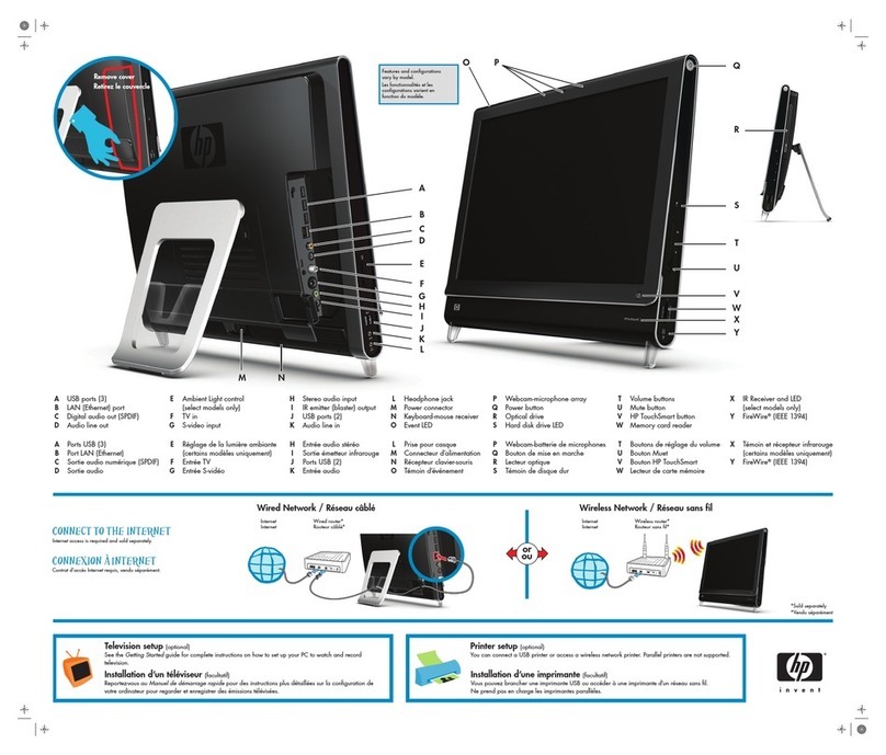
HP TouchSmart IQ520 Connection to the internet

Wincor Nixdorf
Wincor Nixdorf BEETLE operating manual
DTR Industries & C
DTR Industries & C PERO Workstation W1 PRO quick start guide
CompuLab
CompuLab Airtop owner's manual

Lenovo
Lenovo ThinkCentre Edge 91 Podręcznik użytkownika
Asus
Asus Terminator K7 user guide

