Cincinnati CB Series User guide

OPERATION,
MAINTENANCE
AND
SAFETY
MANUAL
FOR
@D~@D~IN!I~ifD
CB
HYDRAULIC
PRESS
BRAKES
CINCINNATI
INCORPORATED
CINCINNATI,
OHIO
45211
EM-234
(FEB
93)
CB HYDRAULIC PRESS BRAKE INDEX
SECTION
1
SECTION 2
SECTION 3
SECTION
4
INSTALLATION 1
LIFTING AND
MOVING
1
FOUNDATION 1
CLEANING 1
LEVELING 1
INITIAL LUBRICATION 2
ELECTRICAL
CONNECTIONS_3
IDENTIFICATION 4
SAFETY
5
OPERATION 10
STANDARD
CONTROLS
10
OPTIONAL
CONTROLS
12
INITIAL
START-UP
OF
NEW
MACHINE
13
DAILY
START-UP
13
SECTION
6
SECTION 7
MAINTENANCE
AND
ADJUSTMENTS
__
23
LUBRICATION
23
HYDRAULIC
OIL
23
OIL
FILLER-BREATHER
23
CHECKING·&SETTING HYDRAULIC
PRESSURE
24
CYLINDERS
24
PUMP
25
VALVES
26
LEVELING
SYSTEM
26
TILT LIMIT
SWITCHES
27
MACHINE
LEVELNESS
28
SWIVEL
END-GUIDE
BEARINGS_28
ELECTRICAL
28
TROUBLESHOOTING
28
MAINTENANCE
CHECK
LIST
__
30
ORDERING REPAIR
PARTS
31,
SECTION 5KNOWING YOUR
PRESS.BRAKE
_14
PERFORMANCE &RATINGS
__
14
PRINCIPLES
OF
OPERATION
_14
TYPES
OF
DIES
15
PUNCHING
CAPACITY
16
STRIPPING CAPACITY
16
ECCENTRIC
LOAD
CAPACITY
_17
OFF-CENTER LOAD CAPACITY
_17
STROKE
CYCLE
TIME
18
SET-UP
AND USE
19
INSERTING
TOOLING
19
SET
MACHINE
CONTROLS_
20
REMOVING
TOOLING
20
BENDING TIPS 21
GAGING 21
BLANK
DEVELOPMENT
22
ORDERING REPAIR PARTS
__
31
RETURNING PARTS FOR
CREDIT
31
SERVICE
31
©
COPYRIGHT
1987
BY
CINCINNATI
INCORPORATED

SECTION 1
Upon
receipt
of
your
CINCINNATI
Hydraulic
Press
Brake
carefully
remove
the
contents
of
the
one
or
more
packing
boxes
shipped
with
the
machine.
All
of
the
machine
options
and
loose
parts)
such.
as
wrenches,
will
be
in
these
boxes.
Check
all
of
the
parts
received
with
the
packing
list.
Claims
for
shortages
or
damaged
parts
should
be
made
within
ten
days.
Remove
all
shipping
paper
from
the
wrapped
parts
of
the
press
brake.
Leave
the
shipping
skids
attached
to
the
machine
until
it
has
been
moved
to
its
final
location.
LIFTING AND MOVING
CINCINNATI CB
Hydraulic
Press
Brakes
are
readily
handled
by
cranes
of
sufficient
capacity
with
chains
or
cables
adjusted
to
the
proper
length
for
even
lifting.
Use
a
timber
brace
bet\veen
the
top
of
the
housings.
A
typical
hitch
is
shown
in
Fi.~re
1.
FIGURE 1
Where
crane
facilities
are
insufficient
in
capacity
or
are
not
available,
rig
the
machine
into
final
location.
When
rigging
into
position,
be
extremely
careful
to
keep
the
machine
supported
evenly
and
to
guard
against
tipping.
CINCINNATI
INCORPORATED
recommends
that
professional
riggers
be
employed
to
handle
the
machine
to
ensure
against
damage
or
injury
to
workers.
If
jacks
are
used
to
lo·w·er
the
machine
onto
the
foundation
bolts,
care
should
be
taken
to
prevent
twisting
of
the
machine.
1
INSTALLATION
FOUNDATION
A
CINCINNATI
CB
Hydraulic
Press
Brake
is
not
a
self-
contained
machine;
that
is,
the
machine
must
be
provided
with
a
rigid
foundation
to
ensure
the
preservation
of
alignment
of
the
housing
and
cross
framing
members.
The
foundation
must
support
the
weight
of
the
machine
without
cracking
or
settling
aut
-of
-level.
For
details
of
the
foundation
recommended
for
your
press
brake
refer
to
the
Foundation
Plan
drawing.
It
is
advisable,
particularly
in
localities
where
unusual
soil
conditions
may
exist,
to
have
your
foundation
plan
approved
by
a
local
registered
civil
engineer.
As
a
final
check,
before
locating
the
press
brake
on
the
foundation,
see
that
the
anchor
bolts
in
your
foundation
coincide
with
the
bolt
hole
spacing
in
the
housing
feet.
CLEANING
Thoroughly
clean
protective
grease
from
all
parts
of
the
machine
with
solvent.
Go
over
the
grease
with
a
rag
wet
with
solvent
and
allow
to
soak.
Use
rags
instead
of
waste.
A
stiff
brush
will
get
into
the
corners.
Do
not
use
an
air
hose
-
pressure
may
drive·
dirt
and
grit
into
bearing
surfaces.
After
cleaning
thoroughly,
wipe
dry
and
make
sure
that
no
grease
or
grit
is
left.
With
oil,
clean
and
flush
the
ram
guides
and
slides,
wiping
off
all
excessive
oil.
Periodic
cleaning
of
the
machine
after
installation
is
advisable.
LEVELING
CINCINNATI
Press
Brakes
are
leveled
by
placing
fIat
steel
shims
of
proper
thicknesses
under
the
press
brake
housing
feet
as
required.
Use
a
precision
level
-
not
a
carpenter's
or
machinist's
leveL
See
Figure
2. Always
wipe
level
and
surface
clean
before
placing
level.
Give
the
bubble
of
the
precision
level
a
half
minute
to
come
to
absolute
rest.
FIGURE 2
After
the
machine
is
level,
retighten
foundation
bolt
nuts
securely.
Recheck
guide
and
slide
alignment.. Do
not
remove
shims.
Alignment
may
not
be
permanent.
Recheck
level
in
afew
weeks.
Do
not
use
any
grouting
around
the
machine.
Leave
the
bed
pit
empty
and
cover
with
steel
plate
(175CB x
12,
230CB x
12,
350CB x
10,
12).
This
condition
is
corrected
by
adding
or
removing
shims
under
one
of
the
rear
housing
feet.
In
the
example,
the
excessive
clearance
was
at
the
right
guide
and
slide.
To
bring
the
alignment
into
tolerance,
shims
could
be
added
under
the
right
rear
housing
foot
or
removed
from
the
left
rear
housing
foot.
The
alignment
must
be
corrected
even
if
it
causes
the
bed
to
be
out-of-leveL
RAM
GUIDE
RAM
CLAMP
(LOOSENED
AND
AWAY
FROM
GUIDE)
o
o
FIGURE 4
RAM
MEASURE
CLEARANCE
AT
TOP
AND
BOTTOM
FIGURE 3
Let
the
machine
down
and
recheck
level.
Repeat
as
often
as
necessary.
Level
the
machine
lengthwise
with
the
level
placed
parallel
to
the
length
of
the
bed
and
in
the
center.
Raise
the
housings
with
leveling
screw
as
shown
in
Figure
3.
Place
the
required
flat
steel
shims
under
the
low
housing
~
both
at
the
front
and
at
the
back.
.'
Level
machine
front-to-back
with
the
level
crosswise
on
the
bed,
first
at
the
right
end
of
the
bed
near
the
housing
and
then
at
the
left
end.
Use
jack
screw
to
insert
or
remove
flat
steel
shims
under
rear
of
both
housings
as
required.
Recheck
and
repeat
until
level.
r---------IMPORTANT
---------.
Before
running
the
machine.
tighten
the
guide
clamp
bolts
to
100
ft.-Ibs.
....--------IMPORTANT-------
........
Do
not
run the machine until
the
phenolic
spacers
are
removed from
each
ram guide, and
the
ram
liners have been
installed
and
properly
lubricated.
INITIAL LUBRICATION
Before
starting
your
hydraulic
press
brake,
the
following
Iu
brication
steps
should
be
taken:
Check
the
ram
guide
and
slide
alignment
to
make
sure
there
is
no
twist
in
the
machine.
This
is
done
by
loosening
the
ram
clamp
bolts
until
the
ram
hangs
free
of
the
guides.
Measure
with
a
feeler
gage
the
clearance
between
the
ram
slide
liner
and
the
ram
guide
at
the
top
and
bottom.
See
Figure
4.
Clearance
at
the
top
of
the
right
slide·
minus
clearance
at
the
bottom
of
the
right
slide,
must
be
within
.004
of
clearance
at
the
top
of
the
left
slide
minus
clearance
at
the
bottom
of
the
left
slide.
1.
Check
hydraulic
reservoir
for
proper
fluid
level
(a
sight
gage
is
located
on
the
rear
of
the
tank).
2.
The
hydraulic
reservoir
is
supplied
with
a
valve.
Before
starting
the
pump,
crack
this
open
to
drain
any
water
that
.
may
have
collected
in
the
tank
during
shipment.
If
no
water
comes
out,
or
when
oil
starts
to
come
out,
close
this
valve
securely.
Repeat
this
check
monthly.
3.
Remove
the
filler-breather
neoprene
shipping
seal
from
under
the
cap.
EXAMPLE:
Left
Clearance
Right
Clearance
4.
Clean
exposed
portions
of
the
leveling
tape.
Since
the
difference
of
.030
is
greater
than
.004,
there
is
a
twist
in
the
machine.
At
top
At
bottom
Difference
.005
-.015
.-
.010
.020
-.000
.020
5.
Place
afew
drops
of
oil
on
the
bottom
stroke
stop
adjusting
screw
and
on
the
level
adjusting
screw.
6.
Service
clevis
pin
grease
fittings..
Complete
lubrication
specifications
and
schedules
are
specified
in
Section
6,
MAINTENANCE
AND
ADJUSTMENTS.
2

.....
--------CAUTION
--------
...
STANDARD PRESS BRAKES
ARE
DESIGNED
FOR AND SHIPPED WITH PETROLEUM BASED
HYDRAULIC FLUIDS, WHICH
ARE
FLAMMABLE.
CHECK APPLICABLE FIRE CODES FOR SPECIAL
PRECAUTIONS.
ELECTRICAL CONNECTIONS
As
shown
on
the
Foundation
Plan
drawing,
suitable
leads
must
be
brought
to
the
machine
into
the
electrical
control
panel
on
the
right
housing.
This
is
the
only
electrical
connection
that
is
necessary.
Be
certain
that
proper
voltage
is
fed
to
the
press
brake,
that
the
lines
are
of
sufficient
capacity
and·
that
a
suitable
ground
conductor
is
attached.
3
NOTE: CINCINNATI INCORPORATED
CB
Hydraulic
Press
Brakes
are
factory
wired
for
460V/3/60HZ
service.
If
service
is
other
than
this,
do
not
remove
warning
tag
from
the
main
disconnect
or
connect
any
power
to
the
machine
until
aCINCINNATI
INCORPORATED
Service
Representative
inspects
and
services
the
machine.
Do
not
start
the
main
drive
motor
until
thoroughly
reading
the
OPERATION
section
of
this
manual
and
aCINCINNATI INCORPORATED
Service
Represent-
ative
is
present.

CB HYDRAULIC PRESS BRAKE
MODEL
175CB
SHOWN
SECTION 2
1.
FOOTSWITCH
2.
BED
3. DIE CLAMPS
4. PALMBUTTON STATION
5. RAM
6.
CYLINDER
7. SERVO LEVELING
VALVE
8.
LEVELING BAND
--
9. RAM
TILT
ADJUSTMENT
10. MAIN CONSOLE
11.
SET-UP
LIGHT
12.
STROKE
CONTROL CAMS
13.
FOOTSWITCH
CONTROL
14.
LEVELING SCREW
6
4
IDENTIFICATION
10
FIGURE 5
1.
RIGHT HOUSING
2.
SWIVEL END-GUIDE
3. DRAIN VALVE
4. FLUID
LEVEL
GAGE
5. FILLER-BREATHER
6. MAIN DRIVE MOTOR &
PUMP
7.
FLOW
DIVIDER
8.
LEFT
HOUSING
9. SLIDE &GUIDE
10.
HYDRAULIC MANIFOLD
11. HYDRAULIC RESERVOIR &
HOUSING BRACE
12.
TILT
LIMIT SWITCHES

SECTION 3
SAFETY RECOMMENDATIONS FOR
HYDRAULIC PRESS BRAKE
OPERATION:
Press
brakes
manufactured
by
CINCINNATI INCOR-
PORATED
comply
with
the
construction
require-
ments
of
the
Occupational
Safety
and
Health
Act
and
the
National
Safety
Standards
of
the
American
National
Standards
Institute.
CINCINNATI
INCORPORATED
also
offers
update
packages
for
older
press·
brakes
to
assist
you
in
your
compliance
and
safety
programs.
The
press
brake
is
a
versatile
and
multi-purpose
machine.
We
recommend
you
evaluate
each
press
brake
operation
in
order
to
determine
the
method
of
point-of-operation
safeguarding
which
best
meets
that
operation.
TIle
press
brake,
tooling,
piece
part
and
method
of
feed
and
removal
must
be
evaluated
for
each
job
before
deciding
on
the·
safeguarding
to
be
used.
CINCINNATI
INCORPORATED
recommends
you
read
and
understand
the
safeguarding,
use
and
care
requirements
of
the
American
National
Standard
for
Press
Brakes,
ANSI
B11.3.
This
is
available
from
the
American
National
Standards
Institute,
11 West
42nd
Street,
New York, New York
10036
and
is
included
with
this
manual.
For
additional
safety
information
we
recommend:
•
Securing
applicable
safety
data
sheets
from
the
National
Safety
CounCil,
1121
Spring
Lake
Drive,
Itasca,
Illinois
60143-3201.
•
Determining
your
responsibilities
under
your
state
and
local
safety
codes
•
Requesting
assistance
from
the
loss
prevention
department
of
your
workmen's
compensation
carrier
Personnel
responsible
for
your
press
brake
operator
training
program,
tooling
set-up,
maintenance,
and
operations
must
read
and
understand
this
Operation,
Safety
and
Maintenance
manual.
No
one
should set-up, operate
or
maintain
this
press
brake
until
they
thoroughly
understand
it
and
know
how
to
do
their
job
safely.
This
safety
information
is
not
intended
as
a
substitute
for
the
Operation
and
Maintenance
sections
of
this
manual.
5
SAFETY
FOR SAFE OPERATION OF YOUR
CINCINNATI PRESS BRAKE
KEEP
CLEAR
OF
THE
POINT-OF-OPERATION
The
purpose
of
a
press
brake
is
to
bend
metal
and
it
is
obvious
that
this
same
capacity
will
sever
arms,
hands,
fingers
or
any
other
part
of
the
body
that
is
in
the
point-of-operation
when
the
ram
is
activated.
During
operation,
all
parts
of
your
body
must
be
completely
clear
of
the
work
area.
NEVER
PLACE
ANY
PART
OF
YOUR
BODY
IN
THE
POINT-OF-
OPERATION
(Die
area).
If
operation
by
more
than
one
person
is
reqUired,
operator
controls
must
be
furnished
for
each
per-
son.
If
foot
controls
are
used~and
your
evaluation
of
that
specific
operation
indicates
safeguarding
is
necessary,
provide
the
necessary
safeguarding
before
any
work
is
performed.
(See ANSI B11.3.)
If
you
use
two-hand
operator
control
station(s)
·as
point-of-operation
safeguarding,
be
certain
that
they
comply
with
ANSI B
11.3.
If
operation
by
more
than
one
person
is
reqUired,
one
person
should
be
responsible
to
see
that
not
only
his·
own
body
is
clear
of
the
point
-of~operation
and
all
moving
parts,
but
also
that
his
co-workers
are
clear
and
entirely
visible
in
a
safe
location,
before
the
press
is
operated.
During
set-up,
maintenance
or
other
work
on
the
machine
which
necessitates
manipulation
Within
the
point-of-operation,
either
the
ram
should
be
at
the
bottom
of
the
stroke
or
it
should
be
blocked
so
the
dies
cannot
close.
The
power
supply
should
be
disconnected
and
locked
OFF.
CONCENTRATE ON YOUR
JOB
Daydreaming,
worrying
about
other
problems
or
other
improper
operation
of
a
machine
could
cripple
you
for life.
Operating
a
press
brake
reqUires
your
complete
attention.
Talking,
joking
or
participating
in
or
watching
horseplay
could
result
in
physical
injury
to
you
...
and
that
is
nothing
to
joke
about.
So
watch
what
you
are
doing
and
concentrate
on
your
job.
NEATNESS IS IMPORTANT
Keep
the
floor
of
your
work
area
clear
of
scrap
and
trash
that
could
cause
you
to
stumble.
Put
scrap
in
the
proper
containers
and
keep
stock
and
finished
work
neatly
arranged.
Be
sure
slippery
surfaces
are
cleaned
up
properly.
Stumbling
and
slipping
can
result
in
painful
and
perhaps
even
fatal
injuries.
Put
all
tools
and
equipment
away
when
you
are
not
using
them.
Only
the
part
you
are
working
with
should
be
on
the
machine
when
it
is
operating.
Even
a
screwdriver
can
be
deadly
if
left
on
the
press
brake
or
lower
die.
PROPER TOOLS ARE IMPORTANT
Use
the
proper
tools
when
working
on
the
press
brake.
An
improper
tool
might
slip
and
cause
lacer-
ations.
When
making
repairs
on
the
machine,
dis-
connect
the
power
source
and
be
sure
the
ram
is
at
the
bottom
of
the
stroke
or
blocked
in
place.
ELIMINATE
lOOSE
AND FLOWING CLOTHING
Loose
or
flowing
clothes
may
be
comfortable,
but
if
they
are
caught
on
the
machine,
it
could
result
in
an
injury
to
you.
Keep
jewelry
to
a
minimum.
That
link. I.D.
bracelet
you
got
for
Christmas
could
cost
you
your
hand
or
finger.
LOOK
THINGS OVER CAREFULLY
Before
operating
your
CINCINNATI
hydraulic
press
brake
t
look
to
see
if
your
machine
is
in
proper
con-
dition.
Are
the
dies
worn?
Are
the
machine's
covers
and
guards
securely
in
place?
Is
the
machine
securely
anchored
to
the
floor?
Are
all
nuts,
bolts
and
screws
tight?
Is
everything
in
proper
operating
condition?
If
not,
report
any
unsafe
condition
or
needed
repair
to
your
supervisor
and
be
sure
the
problem
is
corrected
before
beginning
operations.
The
CINCINNATI
hydraulic
press
brake
you
are
oper-
ating
will
not
produce
a
tonnage
greater
than
the
maximum
rated
machine
capacity
(see
capacity
plate). However,
when
using
short
or
small
area
dies,
the
tonnage
must
be
reduced
to
avoid
damage
to
the
tooling
or
the
bed
and
ram
of
the
machine.
Too
much
tonnage
may
also
cause
a
die
to
rupture
and
cause
injury.
If
your
machine
is
eqUipped
with
ton-
nage
control,
consult
the
Press
Brake
Capacities
bul-
letin
for
the
load
reqUired
to
do
the
job.
If
this
is
less
than
maximum
machine
capacity,
set
the
control
so
not
to
exceed
the
required
force
by
more
than
100/0.
FOR THE SAFE OPERATION
OF
YOUR CI·NCINNATI PRESS BRAKE,
FOLLOW THESE RULES:
1.
Never
place
any
part
of
your
body
in
the
point-
of-operation
(Die
area).
Placing
your
hands
or
any
part
of
your
body
in
the
point-of-operation
may
result
in
serious
injury
or
amputation.
6
2..
Evaluate
each
operation
to
determine
the
point-
of-operation
safeguarding
to
be
used
..
3.
Use
the
point-of-operation
safeguarding
select-
ed~
or
method
of
operation
selected
to
minimize
the
exposure
to
potential
hazards
at
the
point-
of-operation.
4.
For
small
part
insertion
and
removal,
use
a
hand
tooL
DO
NOT
place
your
hands
in
the
point
-of-operation.
5.
Know
how
to
safely
operate
and
adjust
your
CINCINNATI
press
brake.
Review
the
Operation
and
Maintenance
sections
of
this
manual.
6.
Maintain
proper
lighting
levels
and
eliminate
light
glare
to
prevent
eye
strain
and
eye
fatigue.
7.
Protect
your
eyes
from
flying
pieces
of
metal
by
always
wearing
your
safety
glasses.
8.
Always
wear
safety
shoes.
A
heavy
or
pointed
piece
of
stock
could
fall
and
cause
serious
injury
to
your
foot.
9.
Wear
snug
fitting
hand
and
arm
protection
when
handling
rough
or
sharp
edged
stock.
10.
Keep
die
area
free
of
loose
tools
and
materials.
When
placing
stock
in
the
machine
for forming,
be
certain
the
gages
and
stops
are
correctly
set
and
the
edge
of
the
stock
is
against
the
gages.
11.
Stand
clear
of
the
workpiece
with
your
arms
slightly
extended
to
avoid
being
hit
if
the
stock
whips
up
or
down
as
the
bend
is
made.
Be
sure
you
know
how
the
workpiece
will
react
to
the
bend
being
made.
If
the
workpiece
whips-up,
place
your
thumbs
and
fingers
below
the
mate-
rial.
If
the
workpiece
whips-down~
use
the
clamp/stop
feature
of
the
machine
control
so
your
hands
can
be
removed
from
the
workpiece
when
the
bend
is
made.
Set
the
forming
speed
to
avoid
excessive
part
~whip".
12.
Releasing
the
footswitch
of
your
CINCINNATI
press
brake
will
immediately
stop
or
reverse
(depending
upon
the
mode
selection)
downward
travel
of
the
ram
in
case
of
emergency.
13.
When
you
leave
the
machine,
place
the
ram
at
bottom
of
the
stroke
or
place
safety
blocks
in
position
under
the
ram.
Turn
OPERATOR CON-
TROL
selector
to
«OFF"
and
remove
the
key
..
even
if
you
will
be
away
for
only
a
few
minutes.
14.
Have
the
routine
scheduled
maintenance
and
adjustments
performed
as
shown
on
the
Maintenance
Checklist
in
Section
6.
15.
Check
alignm~t
of
the
dies
before
operating
the
machine
after
the
dies
have
been
changed
or
if
the
machine
has
been
idle
overnight..
Improper
alignment
could
cause
chipping
and
flying
chips
can
cause
lacerations
and
eye
injuries.
16.
Report
any
cuts,
bruises
and
all
other
injuries
to
your
supervisor
or
the
medical
department
immediately.
They
are
the
best
judges
of
how
serious
or
minor
the
nature
of
your
injUry
is.
GENERAL GUIDELINES FOR
INSTALLING, REMOVING AND
TRANSFERRING TOOLING (DIES)
Installing,
removing
and
transferring
tooling
is
haz-
ardous
and
should
be
done
with
proper
supervision
by
experienced
set-up
men.
Improper
handling
techniques
can
cause
muscle
,strains,
hernias
or
serious
disabling
injUries.
1.
Transfer
dies
using
the
proper
techniques
for
the
weight
of
the
die{s)
being
handled:
a.
Very
light
dies
(up
to
50
pounds)
can
be
car-
ried
manually
or
transferred
on
a
die
truck.
b.
Dies
weighing
over
50
pounds
or
those
that
are
awkward
to
move
should
be
handled
by
a
hoist.
If
the
punch
or
die
has
tapped
holes
for lifting
attachments,
be
sure
the
proper
size
bolts
are
used.
A
bolt
smaller
in
diameter
than
the
tapped
hole
will
slip
Qut
and
cause
serious
injUry.
If
no
lifting
attachments
are
prOVided
..
use
only
approved
rope
slings
so
the
dies
will
not
be
nicked
or
scratched.
Lift
the
dies
high
enough
to
clear
any
obstruc-
tions
..
but
no
higher.
7
CAUTION
2.
When
installing
and
setting-up
dies:
a.
Clean
the
machine
and
filler
block
surfaces
to
which
the
dies
will
be
fastened.
Always
turn
machine
OFF
and
use
safety
blocks
between
the
bed
and
ram
when
working
in
this
area.
b.
Inspect
the
dies
for
chips,
cracks
or
other
hazardous
conditions.
Wipe
them
off
with
a
clean
cloth.
c.
Always
place
the
machine
control
MODE
selector
in
the
"INCH"
position
so
the
ram
can
only
be
cycled
by
use
of
palmbuttons.
d.
Never
reach
into
or
through
the
die
area
when
.
aligning
the
dies
or
setting
the
gaging.
3.
When
removing
dies
from
the
press
brake:
a.
Clear
the
work
areas
of
all
stock,
containers,
tools
and
other
eqUipment.
b.
After
placing
safety
blocks
between
the
dies
and
turning
OFF
the
machine,
clean
both
upper
and
lower
dies
using
a
bench
brush
and
finally
wipe
clean
with
a
cloth.
c.
Place
the
machine
control
MODE
selector
in
the
"INCH"
position
so
the
ram
can
only
be
cycled
by
use
of
the
palmbuttons.
d.
Never
loosen
the
ram
clamp
bolts
unless
the
dies
are
in
a
closed
position
and
the
drive
motor
has
been
shut
«OFF".
Detailed
step-by-step
instructions
for
installing
and
removing tooling
are
provided
in
the
KNOWING YOUR
PRESS BRAKE
section
of
this
manual.
These
instruc-
tions
should
be
followed
for
safe
installation
and
removal
of
tooling from
your
CINCINNATI
press
brake.
Also
included
in
the
KNOWING
YOUR
PRESS
BRAKE
section
of
the
manual
are
instructions
for
making
bends,
gaging,
blank
development
and
use
of
the
machine
controls.
SAFETY SIGNS
In
order
that
press
brake
operators
and
maintenance
personnel
may
be
warned
of
certain
potential
haz-
ards
that
may
exist
-
unless
specified
procedures
are
followed - a
number
of
warning
signs
are
attached
to
CINCINNATI
Hydraulic
Press
Brakes.
Warning
signs
L
__
.
__
.
__
._
_
__
..
_.
. . . .
--'
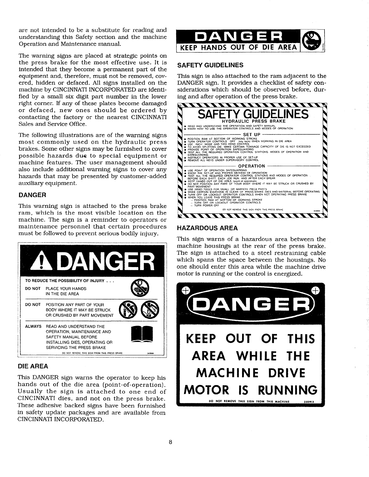
DANGER
DIE AREA
DO
NOl
REMOVE THIS SIGN FROM THIS
MACHINE
2329U
KEEP
OUT OF THIS
AREA
WHILE
THE
MACHINE
DRIVE
MOTOR
IS
RUNNING
----------
seTUP
----------
•POSITION RAM AT BOTTOM
OF
WORK~NG
STROKE
•TURN OPERATOR CONTROLS
'OFF
!kCy
lock)
WHEN WORKING
IN
DIE AREA
•
USE·'No·r
MODE AND TWO HAND CONTROL
•TO AVOID SPLITTING
DIE.
MAKE
CERTAIN TONNAGE. CAPACITY
OF
DIE IS NOT EXCEEDED
•PROVIDE POINT
OF
OPERA
nON
SAFEGUARDING
•TEST
ALL
THE REOUIRED OPERATION CONTROL STATIONS. MODES OF OPERATION
AND
SAFEGUARDING
•INSTRUCT OPERATORS IN PROPER USE
OF
SET·UP
•REMOvE
All·
KEYS
UNDER SUPERVISORY CONTROL
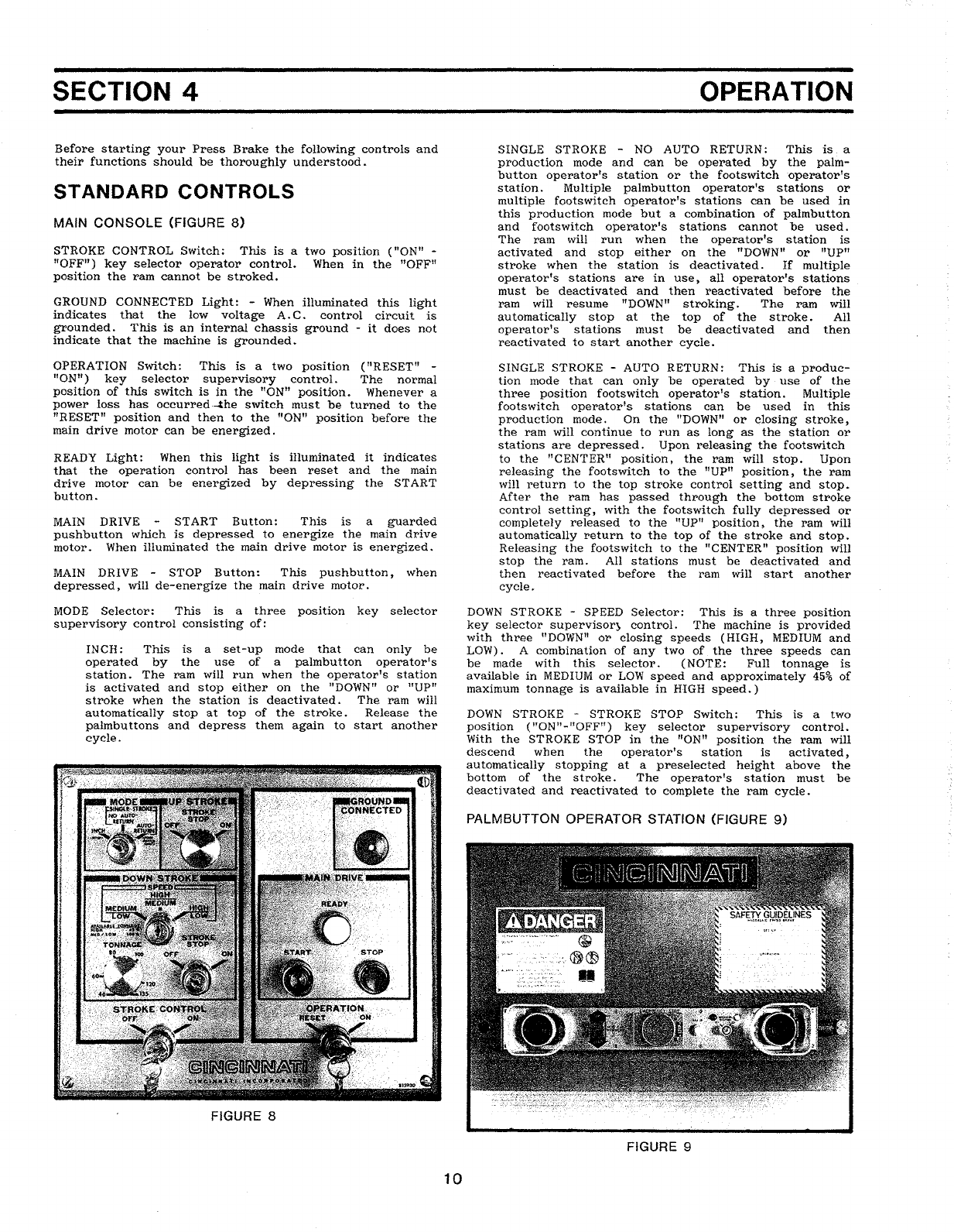
SAFETY GUIDELINES
---------
OPERATION
---------
•USE POINT
OF
OPERATiON SAFEGUARDING
•KNO\V THt: SET·UP
AND
PROPER
METHOD
Of
OPERATION
•TEST ALL THE REOUIRED OPERATOR CONTROL STATiONS AND MODES OF OPERATION
BEFORE EACH 5r1lFT. EACH
JOB
RUN.
AND
AFTER EACH BREAK
•KEEP HANDS OUT OF
OlE
AREA
(pomt
of
operatlco)
•DO NOT POSITlON ANY PART
OF
YOUR BODY WHERE
IT
MAY
BE
STRUCK OR CRUSHED
BY
PABT MOVEMENT
•USE HAND TOOLS FOR
SMALL
OR NARROW PIECE
PMas
•MAKE CERTAIN EVERYONE IS CLEAR OF PRESS BRAKE. DIES
AND
MATERIAL
BEfORE
OPERATING
•TURN OFF OR LOCKOUT OPERATOR CONTROLS WHEN NOT OPERATING PRESS
BRAKE
•WHEN
you
LEAVE THIS
PRESS
BRAKE
.-POSITION
RAM
AT BOTTOM OF WORKING STROKE
---
TURN OFF OR
LOCKOuT
OPERATOR
COtHROlS
._..
TURN POWER OFF
SAFETY
GUIDELINES
HYDRAULIC
PRESS
BRAKE
•READ AND UNDERSTAND THE OPERATION
AND
SAFETY
MANUAL
•KNOW HOW TO USE THE OPERATOR CONTROLS
AND
MODES OF OPERA
lION
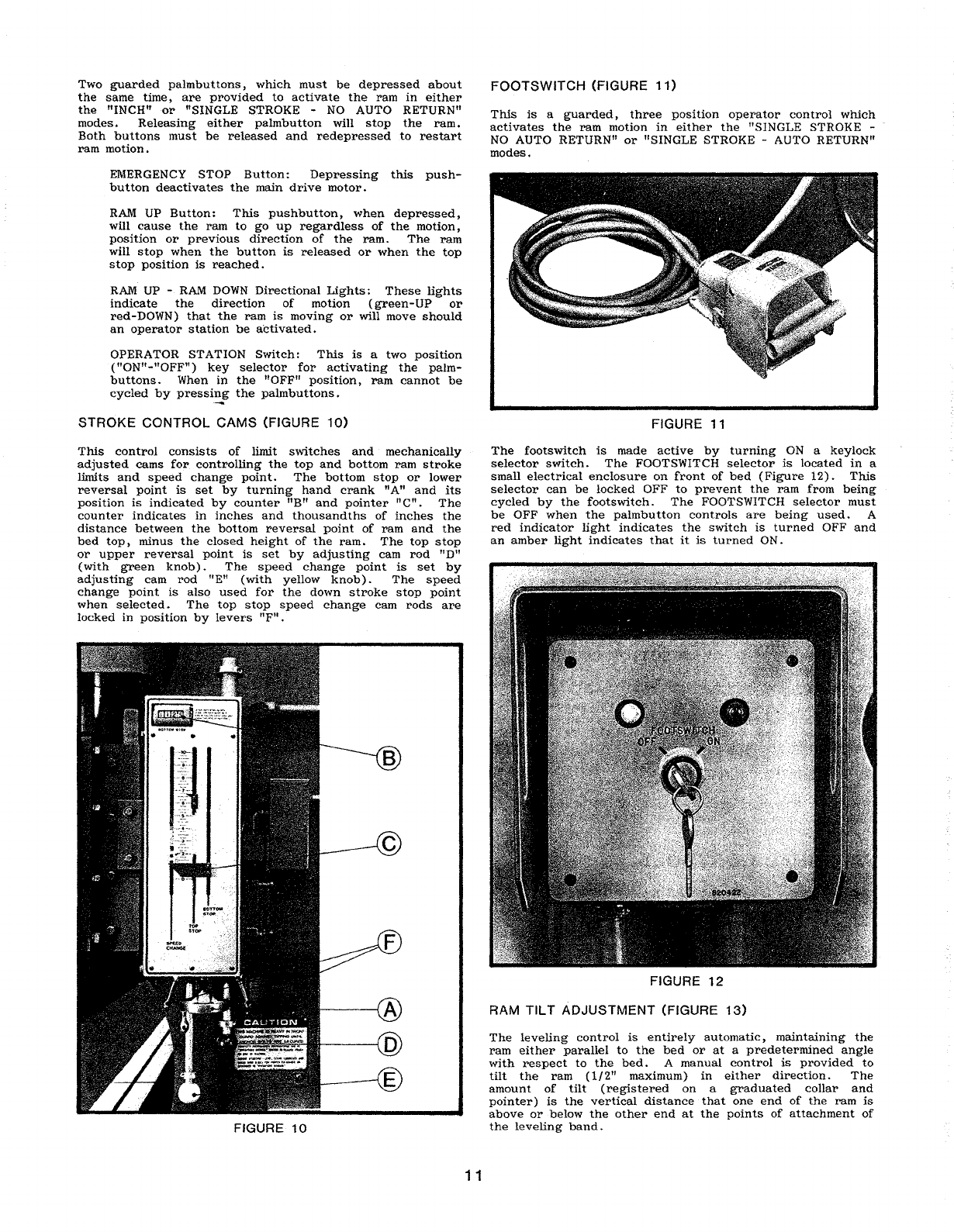
HAZARDOUS
AREA
This
sign
is
also
attached
to
the
ram
adjacent
to
the
DANGER
sign.
It
provides
a
checklist
of
safety
con-
siderations
which
should
be
observed
before,
dur-
ing
and
after
operation
of
the
press
brake.
This
sign
warns
of
a
hazardous
area
between
the
machine
housings
at
the
rear
of
the
press
brake.
The
sign
is
attached
to
a
steel
restraining
cable
which
spans
the
space
between
the
housings.
No
one
should
enter
this
area
while
the
machine
drive
motor
is
running
or
the
control
is
energized.
II
ALWAYS READ AND UNDERSTAND THE
OPERATION,
MAINTENANCE
AND
SAFETY
MANUAL
BEFORE
INSTALLING DIES, OPERATING OR
SERVICING THE PRESS BRAKE
TO REDUCE
THE
POSSIBILITY
OF
INJURY • • •
------------------il
I
I
i
~i
"I
I
DO NOT POSITION ANY PART OF
YOUR
(8
~
"
BODY
WHERE
IT
MAY
BE
STRUCK
~~
",tlt~
..
I
OR
CRUSHED
BY
PART MOVEMENT
'"
-.....~
DO NOT PLACE YOUR HANDS
IN THE DIE AREA
,··A,DANGER
are
not
intended
to
be
a
substitute
for
reading
and
understanding
this
Safety
section
and
the
machine
Operation
and
Maintenance
manual.
The
warning
signs
are
placed
at
strategic
points
on
the
press
brake
for
the
most
effective
use.
It
is
intended
that
they
become
a
permanent
part
of
the
equipment
and,
therefore,
must
not
be
removed,
cov-
ered,
hidden
or
defaced.
All
signs
in&talled
on
the
machine
by
CINCINNATI INCORPORATED
are
identi-
fied
by.a
small
six
digit
part
number
.in
the
lower
right
corner.
If
any
of
these
plates
become
damaged
or
defaced,
new
ones
should
be
ordered
by
contacting
the
factory
or
the
nearest
CINCINNATI
Sales
and
Service
Office.
The
following
illustrations
are
of
the
warning
signs
most
commonly
used
on
the
hydraulic
press
brakes.
Some
other
signs
may
be
furnished
to
cover
possible
hazards
d~
to
special
equipment
or
machine
features.
The
user
management
should
also
include
additional
warning
signs
to
cover
any
hazards
that
may
be
presented
by
customer-added
auxiliary
equipment.
This
warning
sign.
is
attached
to
the
press
brake
ram,
which
is
the
most
visible
location
on
the
machine.
The
sign
is
a
reminder
to
operators
or
maintenance
personnel
that
certain
procedures
must
be
followed
to
prevent
serious
bodily
injury.
:
00
Nor
BE
MOVE THIS SiGN FROM
TtilS
PRESS BRAKE
This
DANGER
sign
warns
the
operator
to
keep
his
hands
out
of
the
die
area
(point-of-operation).
Usually
the
sign
is
attached
to
one
end
of
CINCINNATI
dies,
and
not
on
the
press
brake.
These
adhesive
backed
signs
have
been
furnished
in
safety
update
packages
and
are
available
from
CINCINNATI INCORPORATED.
8

GUARD AGAINST TIPPING
The
design
of
hydraulic
press
brakes
is
such
that
much
of
the
weight
is
concentrated
to
the
front
of
the
machine.
This
sign
cautions
that
the
machine
should
be
guarded
against
tipping
when
moving
or
installing
until
it
is
anchored
to
the
floor.
The
sign
refers
to
the
Operatorts
manual
for
complete
instal-
lation
instructions.
o
CAUTION
0
THIS MACHINE IS HEAVY
IN
FRONT-
GUARD AGAINST TIPPING UNTIL
ANCHOR
BOLTS
ARE SECURED.
COMPLETE
INSTALLATION
INSTRUCTIONS
ARE
IN
"OPERATORS
MANUAL"
PACKED
IN
PLASTIC
POUCH
ON
SIDE
OF
MACHINE.
BEFORE
STARTING
-
LEVEL,
CLEAN,
LUBRICATE
AND
CHECK
RAM
SLIDES
FOR
PROPER
CLEARANCE
AS
DESCRIBED
IN
"OPERATORS
MANUAL"
PRESS
BRAKE
OPERATOR SAFETY
GUIDELINES
•
Be
sure
you
know
your
press
brake
-
capacity,
controls,
operating
modes,
safeguarding
•
Know
and
understand
the
job
you
are
about
to
perform
-material placement, feeding,
movement
of
material
being
formed
•Never place
your
hands
in
the
die
area
•Make
sure
no
one
is
in
backgage
area
at
rear
of
machine
•Tooling,
press
brake
and
gaging
properly
set
for
the
job
•
Always
cycle
the
press
brake
at
least
twice·
with-
out
a
part
in
dies
before
each
shift
and
each
job
•Keep
die
area
free
of
all
unnecessary
material
and
tools
•
Do
not
hang
tools
on
the
ram
•
Adequate
safeguarding
available
and
used
•Keep
your
body
clear
of
workpiece
•Keep
work
area clean
and
orderly
•Keep
alert
-Keep
your
mind
on
the
job
•
Hand
tools
-
personal
protective
devices
avail-
able
and
used
9
•Make
certain
all
persons
are
clear
of
machine
anc'
material
before
operating
•When
you
leave
your
press
brake:
•Place ram
at
bottom
of
stroke
or
block
•Turn
controls
"OFF"
•Turn
power
"OFF"
FAILURE
TO
FOLLOW
SAFE
PRESS
BRAKE
OPERATING
PROCEDURES
MAY
RESULT
IN
SERIOUS
INJURY
TO
YOU
OR
ANOTHER
EMPLOYEE
SAFETY MAINTENANCE CHECK
•SAFEGUARDING
at
point-of-operation
in
proper
adjustment
and
operating
properly
•PINCH POINT
guarding
properly
installed
•OPERATOR CONTROLS
working
O.K.
•OPERATING MODES
functioning
properly
•RAM
starting
and
stopping
properly
•WARNING PLATES clean
and
easily
read
•ELECTRICAL
WIRING
in
good
condition
•CAUTION PAINTING
in
good
condition
•AUXILIARY EQUIPMENT
checked
-
working
properly
•HAND TOOLS
and
personal
protective
equipment
in
good
order
-
readily
available
•
SAFETY
MANUALS
and
OPERATOR
MANUALS
attached
to
machine
•
SCHEDULED
NORMAL
MAINTENANCE
work
completed
SAFETY
IS
PART
OF
YOUR
JOB
•••
THE
MORE
ATTENTION
YOU
PAY
TO
DEVELOPING
SAFE
HABITS,
THE
LESS
THE
CHANCES
OF
INJURY
TO
YOU
AND
YOUR
FELLOW
EMPLOYEES
SECTION 4
Before
starting
your
Press
Brake
the
following
controls
and
their
functions
should
be
thoroughly
understood.
STANDARD CONTROLS
MAIN
CONSOLE
(FIGURE
8)
STROKE
CONTROL
Switch:
This
is
a
two
position
(nON"
-
"OFF")
key
selector
operator
controL
When
in
the
"OFF"
position
the
ram
cannot
be
stroked.
GROUND CONNECTED
Light:-
When
illuminated
this
light
indicates
that
the
low
voltage
A.
C.
control
circuit
is
grounded.
This
is
an
internal
chassis
ground
-
it
does
not
indicate
that
the
machine
is
grounded
..
OPERATION
Switch:
This
is
atwo
position
(flRESET" -
"ON")
key
selector
supervisory
control.
The
normal
position
of
this
switch
is
in
the
"ON
tt
position..
Whenever
a
power
loss
has
occurred-~he
switch
must
be
turned
to
the
"RESET"
position
and
then
to
the
"ON"
position
before
the
main
drive
motor
can
be
energized.
READY
Light:
When
this
light
is
illuminated
it
indicates
that
the
operation
control
has
been
reset
and
the
main
drive
motor
can
be
energized
by
depressing
the
START
button
..
MAIN
DRIVE
START
Button:
This
is
a
guarded
pushbutton
which
is
depressed
to
energize
the
main
drive
motor.
When
illuminated
the
main
drive
motor
is
energized.
MAIN
DRIVE
-
STOP
Button:
This
pushbutton,
'when
depressed,
will
de-energize
the
main
drive
motor.
MODE
Selector:
This
is
a
three
position
key
selector
supervisory
control
consisting
of:
INCH:
This
is
a
set-up
mode
that
can
only
be
operated
by
the
use
of
a
palmbutton
operator's
station.
The
ram
will
run
when
the
operator's
station
is
activated
and
stop
either
on
the
"DOWN"
or
"UP"
stroke
when
the
station
is
deactivated.
The
ram
will
automatically
stop
at
top
of
the
stroke.
Release
the
palmbuttons
and
depress
them
again
to
start
another
cycle.
FIGURE 8
10
OPERATION
SINGLE STROKE -
NO
AUTO
RETURN:
This
is.
a
production
mode
and
can
be
operated
by
the
palm-
button
operator's
station
or
the
footswitch
-operator's
station.
Multiple
paltnbutton
operator's
stations
or
multiple
foots
witch
operator's
stations
can
be
used
in
this
production
mode
but
a
combination
of
palmbutton
and
footswitch
operator's
stations
cannot
be
used.
The
ranl will
run
when
the
operator's
station
is
activated
and
stop
either
on
the
"DOWN"
or
"UP"
stroke
when
the
station
is
deactivated.
If
multiple
operator's
stations
are
in
use)
all
operator's
stations
must
be
deactivated
and·
then
reactivated
before
the
ram
will
resume
trnOWN"
stroking.
The
ram
will
au
tomatically
stop
at
the
top
of
the
stroke.
All
operator's
stations
must
be
deactivated
and
then
reactivated
to
start
another
cycle.
SINGLE
STROKE -AUTO RETURN:
This
is
a
produc-
tion
mode
that
can
only
be
operated
by
use
of
the
three
position
footswitch
operator's
station.
Multiple
footswitch
operator's
stations
can
be
used
in
this
production
mode.
On
the
"DOWN"
or
closing
stroke,
the
ram
will
continue
to
run
as
long
as
the
station
or
stations
are
depressed.
Upon
releasing
the
footswitch
to
the
"CENTER"
position,
the
ram
will
stop.
Upon
releasing
the
footswitch
to
the
"UP"
position)
the
ram
will
return
to
the
top
stroke
control
setting
and
stop.
After
the
ram
has
passed
through
the
bottom
stroke
control
setting,
with
the
footswitch
fully
depressed
or
completely
released
to
the
"UP"
position,
the
ram
will
automatically
return
to
the
top
of
the
stroke
and
stop.
Releasing
the
footswitch
to
the
nCENTER
tt
position
will
stop
the
ram.
All
stations
must
be
deactivated
and
then
reactivated
before
the
ram
will
start
another
cycle~
DOWN STROKE -SPEED
Selector:
This
is
a
three
position
key
selector
supervisor)
control.
The
machine
is
provided
with
three
"DOWN"
or
closing
speeds
(HIGH,
PvlEDIUM
and
LOW).
A
combination
of
any
two
of.
the
three·
speeds
can
be
made
with
this
selector.
(NOTE:
Full
tonnage
is
available
in
MEDIUM
or
LOW
speed
and
approximately
45%
of
maximum
tonnage
is
available
in
HIGH
speed.)
DOWN
STROKE -STROKE
STOP
Switch:
This
is
atwo
position
("ON"-
If
OFF
lt
)
key.
selector
supervisory
control.
With
the
STROKE
STOP
in
the
"ONn
position
the
ram
will
descend
when
the
operator's
station
is
activated,
automatically
stopping
at
a
preselected
height
above
the
bottom
of
the
stroke.
The
operator's
station
must
be
deactivated
and
reactivated
to
complete
the
ram
cycle.
PALMBUTTON OPERATOR
StATION
(FIGURE
9)
FIGURE 9
Two
guarded
palmbuttons,
which
must
be
depressed
about
the
same
time,
are
provided
to
activate
the
ram
in
either
the
"INCHttor
"SINGLE
STROKE
-NO
AUTO
RETURN"
modes.
Releasing
either
palmbutton
will
stop
the
ram.
Both
buttons
Inust
be
released
and
redepressed
to
restart
ram
motion.
EMERGENCY STOP
Button:
Depressing
this
push-
button
deactivates
the
main
drive
motor.
RAM
UP
Button:
This
pushbutton,
when
depressed,
will
cause
the
ram
to
go
up
regardless
of
the
motion,
position
or
previous
direction
of
the
ram.
The
ram
will
stop
when
the
button
is
released
or
when
the
top
stop
position
is
reached.
RAM
UP -.
RAM
DOWN
Directional
Lights:
These
lights
indicate
the
direction
of
motion
(
green
-
UP
or
red-DOWN)
that
the
ram
is
moving
or
will· move
should
an
operator
station
be
activated.
OPERATOR
STATION
Switch:
This
is
a
two
position
("ONU_HOFF")
key
selector
for
activating
the
palm-
buttons.
When
in
the
ttOFF
fJ
position,
ram
cannot
be
cycled
by
pressing
the
palm
buttons.
STROKE
CONTROL
CAMS
(FIGURE
10)
This
control
consists
of
limit
switches
and
mechanically
adjusted
cams
for
controlling
the
top
and
bottom
ram
stroke
limits
and
speed
change
point.
The
bottom
stop
or
lower
reversal
point
is
set
by
turning
hand
crank
nAft
and
its
position
is
indicated
by
counter
nB"
and
pointer
"en.
The
counter
indicates
in
inches
and
thousandths
of
inches
the
distance
between
the
bottom
reversal
point
of
ram
and
the
bed
top,
minus
the
closed
height
of
the
ram.
The
top
stop
or
upper
reversal
point
is
set
by
adjusting
cam
rod
uD"
(with
green
knob)
.
The
speed
change
point
is
set
by
adjusting
cam
rod
"En
(with
yellow
knob).
The
speed
change
point
is
also
used
for
the
down
stroke
stop
point
when
selected.
The
.top
stop
speed
change
cam·
rods
are
locked
in
position
by
levers
"F
n•
FIGURE·
10
11
FOOTS
WITCH
(FIGURE
11)
This
is
a
guarded,
three
position
operator
control
which
activates
the
ram
motion
in
either
the
"SINGLE
STROKE -
NO
AUTO
RETURNu
or
"SINGLE
STROKE
-AUTO
RETURN"
modes.
FIGURE 11
The
footswitch
is
made
active
by
turning
ON
a
keylock
selector.
switch.
The
FOOTSWITCH
selector
is
located
in
a
small
electrical
enclosure
on
front
of
bed
(Figure
12).
This
selector
can
be
locked
OFF
to
prevent
the
ram
from
being
cycled
by
the
footswitch.
The
FOOTSWITCH
selector
must
be
OFF
when
the
palmbutton
controls
are
being
used.
A
red
indicator
light
indicates
the
switch
is
turned
OFF
and
an
amber
light
indicates
that
it
is
turned
ON.
FIGURE
12
RAM
TILT
ADJUSTMENT
(FIGURE
13)
The
leveling
control
is
entirely
automatic,
maintaining
the
ram
either
parallel
to
the
bed
or
at
a
predetermined
angle
with
respect
to
the
bed.
A
manual
control
is
provided
to
tilt
the
ram
(1/2"
maximum)
in
either
direction.
The
amount
of
tilt
(registered
on
a
graduated
collar
and
pointer)
is
the
vertical
distance
that
one
end
of
the
ram
is
above
or
below
the
other
end
at
the
points
of
attachment
of
the
leveling
band.

To
operate
the
press
brake
with
the
bed
and
ram
parallel,
the
graduated
collar
and
pointer
should
be
set
to
their
"ZERO"
marks.
Servicing
and
adjusting
the
tilt
control
is
covered
in
the
MAINTENANCE
section
of
this
manual.
FIGURE
13
...----------CAUTION---------..
WHEN
OPERATING
AT
THE
EXTREME
LIMITS
OF
STROKE,
THE
FULL
LENGTH
OF
STROKE
SHOULD·
BE
REDUCED
BY
THE
AMOUNT
,OF
THE
RAM
TIL
T
FOR
OPERATION
IN
A
TILTED
POSITION
TO
PREVENT
LEFT
PISTON
FROM
STRIKING
THE
TOP
OR
BOTTOM
OF
THE
CYLINDER.
The
maximum
allowable
tilt
is
112
ft
in
the
length
between
the
tape
anchor
points.
If
this
tilt
is
exceeded,
the
out-of-Ievel
limit
switches
will
stop
the
ram
by
de-energizing
the
main
pump
motor.
SET-UP
LIGHTS (FIGURE
5)
This
light'is
mounted
on
front
side
of
the
main
electrical
enclosure.
The
green
Ughtcomes
on
whenever
the
ram
is
at
the
bottom
reversal
position.
OPTIONAL CONTROLS
UP
STROKE
-
STROKE
STOP
Switch
(FIGURE
14)
This
is
a
two
position
("ON"-"OFF
n)
key
selector
supervisory
control
located
on
the
main
console.
When
in
the
nON"
position
the
ram
will
automatically
stop
immediately
after
passing
through
the
bottom
reversal
point.
All
operator
controls
being
used
must
be
released
and
reactivated
to
restart
the
return
stroke
of
the
ram.
This
con
trol
can
be
used
in
all
modes.
TONNAGE
CONTROL
The
tonnage
control
consists
of
an
adjustable
selector
mounted
on
the
main
console.
The
maximum
tonnage
for
"centered
tf
loads
is
limited
by
the
setting
of
this
selector.
Upon
building
up
to·
the
pre-selected
tonnage,
the
ram
will
automatically
reverse
from a
downward
to
an
upward
direction.
12
Actual
forming
tonnage
in
high
speed
is
approximately
45%
of
the
tonnage
control
setting.
FIGURE
14
IMPORTANT
---------..
The
hydraulic
components
and
machine
frame
members
are
safeguarded
against
overload
by
both
a
pressure
transducer
and
a
relief
valve
in
the
circuit.
However,
care
must
be
taken
to
provide
enough
area
under
upper
and
lower
dies
to
prevent
them
from
sinking
into
the
bed
top
or
ram
nose
due
to
highly
concentrated
loads.
ThiS
is
the
shaded
area
shown
in
Figure
15.
The
minimum
area
(sq.
in.)
for
each
die
to
prevent
sinking
may
be
calculated
by
this
formula:
MAXIMUM
TONNAGE
Die
Area
=
15
An
example
for
a
135
ton
machine:
the
minimum
die
area
is
135
divided
by
15,
or
9
square
inches
..
ADDITIONAL
FOOTSWITCHES
AND/OR
PALMBUTTONS
The
operation
of
these
controls
is
the
same
as
the
standard
controls.
Additional
selector
switches
are
provided
for
selecting
left,
right
or
both
controls.
MULTIPLE DEPTH
STOPS
(FIGURE
16)
With
this
option
a
total
of
four
distinct
pre-set
bottom
reversal
points
are
available.
The
No. 1
stop
is
the
standard
bottom
stop.
Stops
No.2,
3
and
4
are
set
by
adjusting
micrometer
barrels
which
are
added
to
the
bottom
s
top
cam
on
the
right
hand
side
of
the
machine.
T,he
press
brake
operator
can
select
which
of
the
four
stops
he
wants
by
a
portable
s~lector
switch,
which
can
be
moved
any
place
along
the
front
of
the
press
brake.
FIGURE
15
FIGURE
16
INITIAL
START-UP
OF NEW
MACHINES
.......
-------IMPORTANT
---------a
A
CINCINNATI
INCORPORATED
Service
Repre-
sentative
should
be
present
during
the
initial
start-up
of
your
Press
Brake.
Before
starting
the
drive
motor
the
following
checks
should
be
made.
A.
Installation
has
been
completed
per
the
instructions
given
in
Section
1
of
this
manual
including:
Foundation
Cleaning
Leveling
Initial
lubrication
(including
oil
level
and
water
in
the
tank)
Electrical
connections
and
service
B.
All
options
have
been
installed
on
the
machine.
13
C.
The
tilt
limit
switches
should
be
properly
adjusted
with
the
ram
and
bed
parallel
(see
Section
6 -
MAINTENANCE
AND
ADJUSTMENT).
D.
A
complete
visual
inspection
of
the
machine
has
been
made.
For
the
initial
start-up
of
the
press
brake
the
main
drive
motor
should
be
jogged
with
the
START
and
STOP
buttons
to
verify
that
the
direction
of
its
rotation
agrees
with
the
arrow.
After
this
has
been
done
t
the
START
button
can
be
depressed
bringing
the
motor
and
pump
up
to
full
speed.
Before
cycling
the
ram,
a
final
check
of
the
machine
level
should
be
made
and
adjusted
as
described
in
Section
1 -
INSTALLATION.
Although
the
operating
pressures
(main
relief
and
counter-
balance)
have.
been
factory
set,
they
should
-now
be
rechecked
and
adjusted
if
necessary,
before
further
stroking
of
the
machine.
Detailed
instructions
for
setting
these
pressures
are
given
in
Section
6
of
this
manual.
All
controls,
electrical
functions,
and
safety
features
of
the
press
brake
should
now
be
checked
for
satisfactory
operation.
Check
the
level
of
the
bed
and
ram
with
a
dial
indicator
as
described
in
Section
6
of
this
manual.
Before
installing
tooling
and
attempting
to
make
bends,
Section
5 - KNOWING
YOUR
PRESS BRAKE
of
this
manual
should
be
read
and
thoroughly
understood.
DAILY
START-UP
At
beginning
of
a
new
shUt,
after
every
break
t
at
start
of
a
new
job
,or
when
machine
is
started
after
an
extended
off
period
(several
hours
or
longer)
t
the
following
procedure
is
recommended:
1.
Check
reservoir
oil
level.
2.
Let
the
pump
idle
for
10
to
15
minutes
to
warm
the
oil.
3.
Check
controls
for
proper
operation.
4.
Verify
that
all
required
safety
devices
and
procedures
are
being
used
and
are
operating
properly.
5.
Verify
that
all
selectable
or
adjustable
controls
are
positioned
correctly
for
the
set-up
or
job
to
be
run.
NOTE:
Before
the
main
drive
motor
can
be
started,
the
main
console
OPERATION
switch
must
be
turned
to
"RESET"
and
back
to
the
"ON"
position.
An
illuminated
READY
light
indicates
that
the
motor
will
start
when
the
START
button
is
depressed
.
The
most common
reason
for
inability
to
start
the
main
motor
is
that
the
ram.
has
tilted
beyond
its
limits
or
that
the
tilt
limit
switches
are
improperly
set.
See
Section
6
of
this
manual
for
releveling
the
ram
and
adjusting
the
tilt
limit
switches.
6.
Check
for
tools,
loose
material
or
persons
in
point-of-
operation
or
at
rear
of
machine.
7.
Know
the
machine.
Thoroughly
read
this
manual
and
become .
familiar
with
all
of
the
controls
and
how
they
affect
ram
motion.
Run
the
machine
without
tooling
and
become
familiar
with
its
Ufeel".
8.
Be
safety
conscious.
Always
follow
the
safety
pre-
cau
tions
outlined
in
this
manual.
9.
Select
proper
tooling
for
the
job.
Make
sure
the
dies
are
in
good
condition.
10.
Never
place
any
part
of
your
body
in
the
die
area.
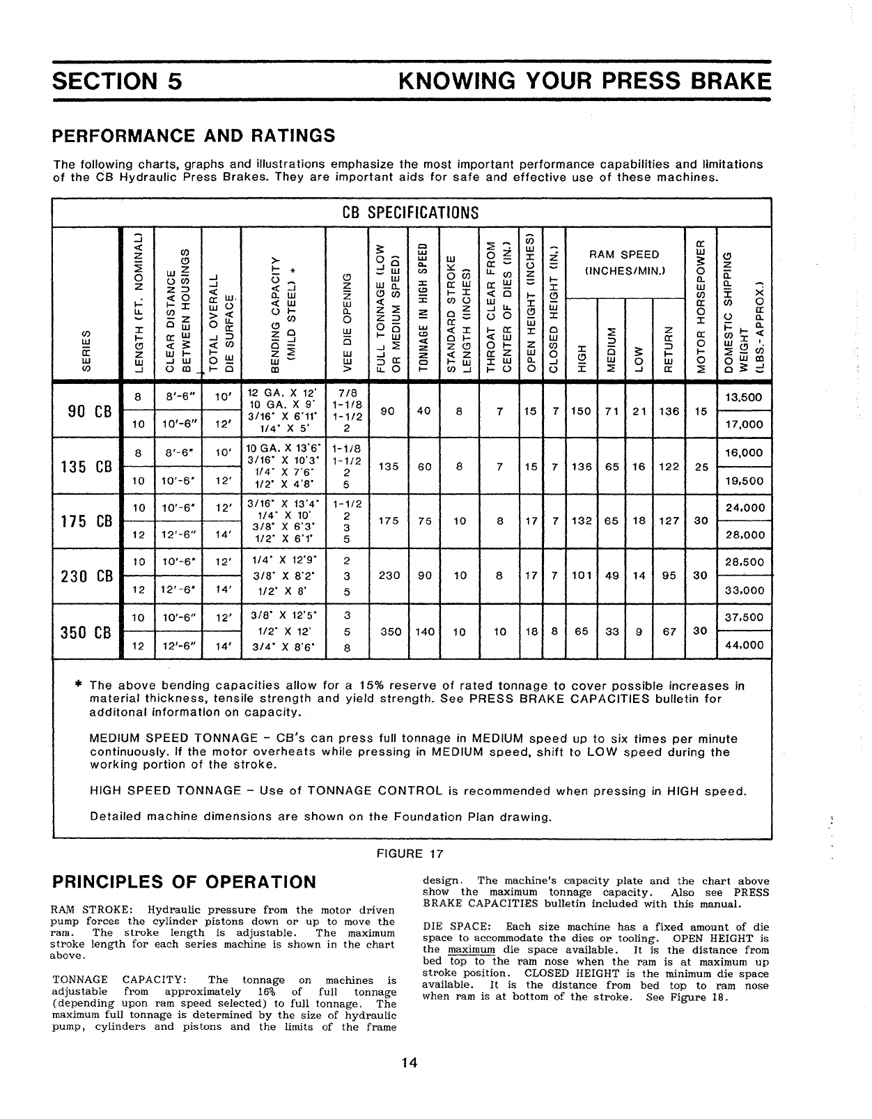
SECTION 5
PERFORMANCE AND RATINGS
KNOWING YOUR PRESS BRAKE
The
following
charts,
graphs
and
illustra
tions
emphasize
the
most
important
performance
capabilities
and
limitations
of
the
CB
Hydraulic
Press
Brakes.
They
are
important
aids
for
safe
and
effective
use
of
these
machines.
CB
SPECIFICATIONS
:J
~
-W
a:
<t:
~
Q
~
W-W
ZC/) w0
J:
:i.
RAM SPEED "
"
>-
o-
wW
~
~
.....)0
a.
CI:
-
()
z
w~
I-
*
_w
(I.)
~-
u..
en
zClNCHES/MINJ 0
a::
0(.)C/) -s 0
c:>
w
ow
~
l-
n.
z
..J
<t:
:J
z
wa.
::t:
a:w
ex:
-
J:
w
Q.
z=>
<Z
(!)C/)
C)
I-X
oct
e
J:
x
«0
w.
a..
w:i:
.-
~
C/)
t-=
cr:
<t:
W
~~
enu
w
::r:
cr
en
0
t;J:
(,)
w
o~
U.
ill
U. W
(.)
...
a..
~
-J
(!)
0
a:
-
-z
><C/) 0
z::>
(,)
0
ijj
J:
:r:
()
Q.
Ow
0
u.
(!)
0-
0:-
~
...
0-
X
a:
0w
I-~
w
oct
J:
I-
a:
J:
0~z<
C/)
I-
((w
-J
::>
z0
(!)
01-
«
ill
ill
cr:
0:
(/)J:
ill
«
~
en
0
-J
-J~
<C
0
t-
Z
en
::>
0
WC!)
I
(!)
«
~
2
Z(!}
J:
Ci
::>
en
a:
z
ill
l-
I-
ZW-So: «z
a:
z
ill
0
;:
t--
I-
~-
~
-z0w0
OW
en
ww
...JW
0W
ill
0
t-w
J:
ill
a..
-I
0
ill
(/)
-I
(,)
en
__
I-
e
en
>
~o
....
C/)....J
I-
00
(.)
I
:::E
..J
((
:::E
o~
=
8
8'-6"
10'
12
GA.X
12'
7/8
13,500
90
CB
10
GA.
X
9'
1-1/8
90
40
87
15
7
150
71
21
136
15
3/16-
X6'11-
1-1/2
10
10'-6"
12'
1/4-
X
5'
2
17,000
8
8'-6"
10'
10
GA.
X
13'6-
1-118
16,000
135
CB
3/16-
X
10'3-
1-112
135
60
87
15
7
136
65
16
122
25
1/4-
X
7'6-
2
10
10'-6-
12'
1/2- X 4
'a-
5
19,500
10
10'-6"
12'
3/16-
X
13'4-
1-1/2
24,000
175
CB
1/4-
X10' 2
175
75
10
8
17
7
132
65
18
127
30
3/8-
X
6'3-
3
12
12'-6"
14'
1/2"
X
6'1·
5
28,000
10
10'-6"
12'
1/4"
X
12'9-
2
28,500
230
CB
3/8"
x
8'2"
3
230
90
10
8
17
7
101
49
14
95
30
12
12'-6-
14'
1/2-
X
8'
5
33,000
10
10'-6"
12'
3/8"
X12'5" 3
37,500
350
CB
1/2-
x12' 5
350
140
10
10
18
8
65
33
9
67
30
12
12
1
-6"
14'
3/4·
X
S'6"
a
44,000
*
The
above
bending
capacities
allow
for
a15%
reserve
of
rated
tonnage
to
cover
possible
increases
in
material
thickness,
tensile
strength
and
yield
strength.
See
PRESS
BRAKE
CAPACITIES
buffetin
for
additonal
information
on
capacity.
,
MEDIUM
SPEED
TONNAGE
.....
CB's
can
press
full
tonnage
inMEDfUM
speed
up
to
six
times
per
minute
continuously.
If
the
motor
overheats
while
pressing
in
MEDIUM
speed,
shift
to
LOW
speed
during
the
working
portion
of
the
stroke.
HIGH
SPEED
TONNAGE
-
Use
of
TONNAGE
CONTROL
is
recommended
when
pressing
in
HIGH
speed_
Detailed
machine
dimensions
are
shown
on
the
Foundation
Plan
drawing.
FIGURE
17
PRINCIPLES
OF
OPERATION
RAM
STROKE:
Hydraulic
pressure
from
the
motor
driven
pump
forces
the
cylinder
pistons
do\vn
or
up
to
move
the
ram.
The
stroke
length
is
adjustable.
The
maximum
stroke
length
for
each
series
machine
is
shown
in
the
chart
above.
TONNAGE
CAPACITY:
The
tonnage
on
machines
is
adjustable
from
approximately
16%
of
full
tonnage
(depending
upon
ram
speed
selected)
to
full
tonnage.
The
maximum
full
tonnage
is
determined
by
the
size
of
hydraulic
pump,
cylinders
and
pistons
and
the
limits
of
the
frame
14
design.
The
machine's
capacity
plate
and
the
chart
above
show
the
maximum
tonnage
capacity.
Also
see
PRESS
BRAKE CAPACITI·ES
bulletin
included
with
this
manual.
DIE
SPACE:
Each
size
machine
has
a
fixed
amount
of
die
space
to
accommodate
the
dies
or
tooling.
OPEN HEIGHT
is
the
maximum
die
space
available.
It
is
the
distance
from
bed
top
to
the
ram
nose
when
the
ram
is
at
maximum
up
stroke
position.
CLOSED
HEIGHT
is
the
minimum.
die
space
available.
It
is
the
distance
from
bed
top
to
ram
nose
when
ram
is
at
bottom
of
the
stroke.
See
Figure
18.
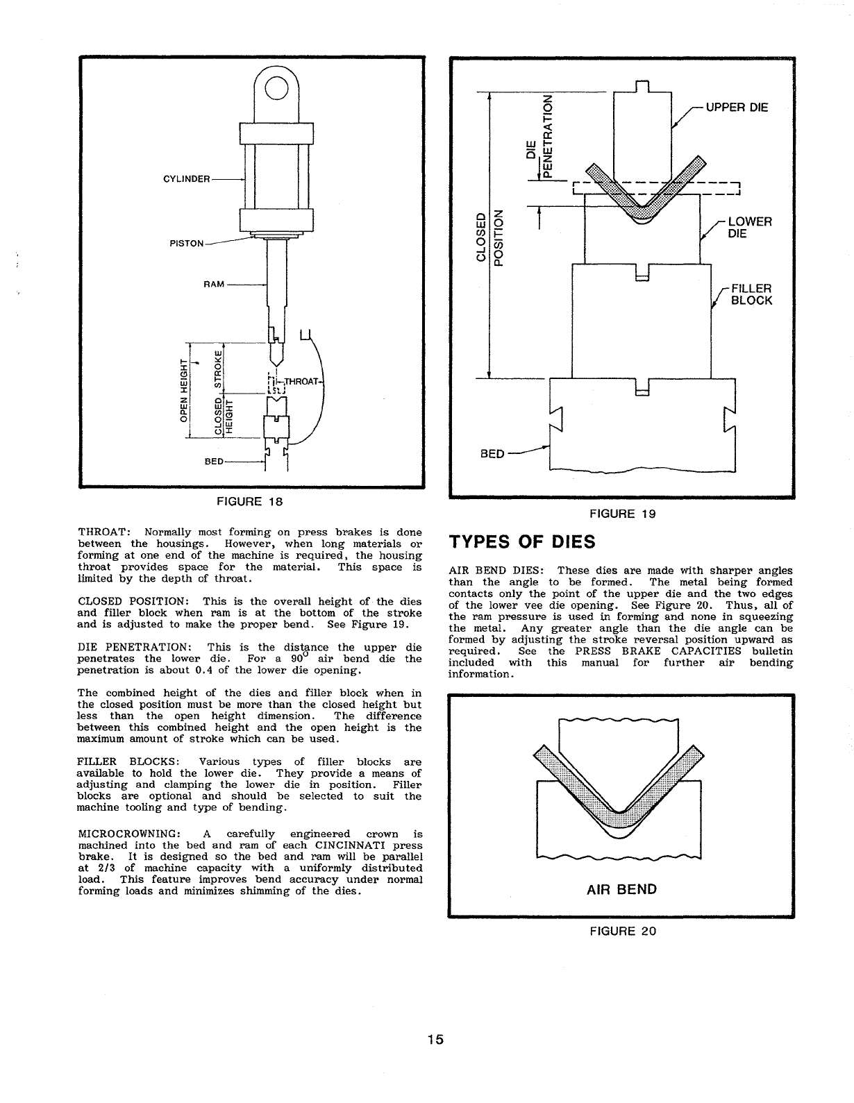
CYLINDER
RAM
FILLER
BLOCK
LOWER
DIE
UPPER
DIE
oZ
W0
(J)i=
°00
..J 0
0a.
PISTON
o
BED
BED
rr-;;r-,,_
~
~r
~l
~,!
Wi
~
,,~;rHROAT
J:
-+--
lStJ
ffi·
~
....
0..
(f)J:
o
g~
OJ:
FIGURE
18
FIGURE
19
THROAT:
Normally
most
forming
on
press
brakes
is
done
between
the
housings.
However,
when
loltg
materials
or
forming
at
one
end
of
the
machine
is
required,
the
housing
throat
provides
space
for
the
material.
This
space
is
limited
by
the
depth
of
throat.
CLOSED
POSITION:
This
is
the
overall
height
of·
the
dies
and
filler
block
when
ram
is
at
the
bottom
of
the
stroke
and
is
adjusted
to
make
the
proper
bend.
See
Figure
19.
DIE PENETRATION:
This
is
the
distance
the
upper
die
penetrates
the
lower
die.
For
a
90°
air
bend
die
the
penetration
is
about
0.4
of
the
lower
die
opening.
The
.
combined
height
of
the
dies
and
filler
block
when
in
the
closed
position
must
be
more
than
the
closed
height
but
less
than
the
open
heigh
t
dimension.
The
difference
between
this
combined
height
and
the
open
height
is
the
maximum
amount
of
stroke
which
can
be
used.
FILLER BLOCKS:
Various
types
of
filler
blocks
are
available
to
hold
the
lower
die.
They
provide
a
means
of
adjusting
and
clamping
the
lower
die
in
position.
Filler
blocks
are
optional
and
should
be
selected
to
suit
the
machine
tooling
and
type
of
bending.
MICROCROWNING: A
carefully
engineered
crown
is
machined
into
the
bed
and
ram
of
each
CINCINNATI
press
brake.
It
is
designed
so
the
bed
and
ram
will
be
parallel
at
2/3
of
machine
capacity
with
a
uniformly
distributed
load.
This
feature
improves
bend
accuracy
under
normal
forming
loads
and
minimizes
shimming
of
the
dies.
TYPES OF DIES
AIR BEND
DIES:
These
dies
are
made
with
sharper
angles
than
the
angle
to
be
formed.
The
metal
being
formed
contacts
only
the
point
of
the
upper
die
and
the
two
edges
of
the
lower
vee
die
opening.
See
Figure
20.
Thus,
all
of
the
ram
pressure
is
used
in·
forming
and
none
in
squeezing
the
metal.
Any
greater
angle
than
the
die
angle
can
be
formed
by
adjusting
the
stroke
reversal
position
upward
as
required.
See
the
PRESS
BRAKE
CAPACITIES
bulletin
included
with
this
manual
for
further
air
bending
information.
AIR BEND
FIGURE
20
15

BOTTOMING
DIES:
The
primary
purpose
of
bottoming
dies
is
to
provide
greater
accuracy
than
air
bend
dies.
They
can
also
be
used
to
obtain
a
relatively
sharp
inside
corner.
They
are
made
in
matched
pairs,
according
to
the
thickness
of
the
stock
to
be
formed
and
radius
required.
See
Figure
21.
These
dies
require
three
to
ten
times
as
much
pressure
as
air
bend
dies.
Other
types
of
bottoming
dies
are
coining
dies,
used
to
obtain
a
sharp
inside
radius,
multiple
bend
and
channel
dies,
and
radius
bend
dies.
DIE
SETS
Special
care
should
be
taken
when
operating
die
sets
with
guide
pins
and
bushings.
The
top
stop
position
should
be
set
so
the
bushings
never
leave
the
guide
pins
when
the
ram
makes
an
UP
STROKE.
Re-entry
of
the
guide
pins
in
to
the
bushings
may
be
difficult,
if
not
impossible.
PUNCHING
CAPACITY
CINCINNATI
Hydraulic
Press
Brakes
are
rated
to
perform
punching
loads
up
to
66%
of
the
maximum
machine
capacity
when
punching
mild
steel
using
self-contained
units
on
an
occasional
basis.
When
punching
is
to
be
performed
on
a
continuous
production
basis,
with
dedicated
die
sets
or
high
tensile
(70,000
PSI)
material
is
to
be
processed,
the
punching
capacity
is
reduced
to
50%
of
the
maximum
machine
capacity,
Figure
23.
Additional
punching
capacity
can
be
obtained
by
stepping
the
punches
(Figure
24)
on
multiple
levels.
For
special
punching
applications,
where
die
sets
or
special
machine
features
(for
example,
wide
bed,
deep
throat,
etc.)
are
required,
consult
CINCINNATI
INCORPORATED.
BOTTOMING
FIGURE 21
CINCINNATI
INCORPORATED
can
provide
many
other
types
of
standard
and
special
dies,
some
of
which
are
shown
in
Figure
22.
MAXIMUM
PUNCHING
CAPACITY
CB
SERIES
TONS/LEVEL
MILD
STEEL
HI-TENSILE
90
CB
60
45
135
CB
90
67.5
175
CB
115
87.5
230
CB
150
115
350
CB
230
175
T=
METAL THICKNESS
THREE
LEVELS
TWO
LEVELS
ONE
LEVEL
FIGURE
23
MULTIPLE
lEVEL
PUNCHING
RADIUSCHANNEL
OFFSET
3OR 4
WAY
VEE DIE
FIGURE
24
STRIPPING
CAPACITY
A
stripping
load
is
a
force
which
occurs
on
the
up
stroke
of
the
ram.
The
direction
of
this
type
of
load
is
down
on
the
ram
and
up
on
the
bed
(the
reverse
of
forming
and
punching
loads).
Figure
25
shows
the
maximum
stripping
load
available
at
the
center
of
the
machine.
HEMMING
FIGURE
22
16

FIGURE
25
ECCENTRIC
LOAD
CAPACITY
(FRONT-TO-BACK)
Occasionally
special
forming
or
punching
set
-ups
are
made
which
do
not
have
their
load
centers
located
on
the
bed
and
ram
centerlines.
When
this
condition
exists,
care
must
be
taken
not
to
exceed
the
maximum
eccentric
(front-to-back)
load
capacity
of
the
press
brake.
I I
I I MACHINE C
T.
•
fL
~-
~~
350
LOAD
340
330
//
320
VI
310
h
lf
300
1/
290
/'
280
270
I /
'/
260
(!)
<c~·V~'
Z
250
0
~~Y
Z
:<0+
,,()
240
W
"f:JJ
+/
CO
~<;j
o~
~
230
a:
-~,,:>,:>.,/
220
0
/ V
~
u.
~
210
W
-","
/
//
...J
200
m
/l,;'
/
~/
«
190
..J
./
V//
;(
/"
/'
~~./'l
180
>
~
«
~
~
170
W
~i--
60
(!)
.,u
~,\.
4<
?,.~
.....
0
150
Z
V
ov~~1
~
z
140
0
V
V?'~
~~/'l
~
J-
./
~
,-/
V
~
~
130
-"
./
,,~
f~'
~
120
",..
",
~
--'
"f..
""\~
./
110
.-'
V""
~
~~~v
~~V
'\0
100
~
~
~
~
I~
-
,-
\~
.
~,,\.
V
90
",/
~
~
CO,
J!l
80
."",...
""",
f\~~C
I
\0
~""i.
"?'
...",.
~
~
----
---
ce
'/-.
~1._
'---
70.
~
'/-.~
::..,..
oc?J
60
.-
:..----
-:::::~~
9I
50
--
~
.,.,.,,-
40
MAXIMUM
MACHINE ECCENTRIC
SERIES
LOAD
CAP.
(
INCH-TON)
90
CB
100
135
CB
100
175
CB
200
230
CB
200
350
CB
300
~
-CENTERLINE
L -
LOAD
(FORMING
OR
PUNCHING) -TONS
d - DISTANCE BETWEEN
MACHINE
tt.
&LOAD
~
INCHES
MACHINE
MAXIMUM
SERIES STRIPPING
LOAD (TONS)
90
CB
9.0
135
CB
13.5
175
CB
17.5
230
CB
23.0.
350CB
35.0
MACHINE t
dXL
MUST
BE
EQUAL
TO
OR
LESS
THAN
MAXIMUM
ECCENTRIC
LOAD
CAPACITY
12
60
48
36
24
12
FIGURE
26
...---------
IMPORTANT
--------...
DISTANCE FROM
~
MACHINE TO
~
LOAD
L
(IN.)
Exceeding
the
eccentric
load
capacity
could
damage
the
slides
and
guides,
sink
upper
bed
bolts
into
their
counterbores
causing
bed
to
become
loose,
or
overstress
upper
bed
and
die
clamp
bolts
causing
them
to
shatter
and
possibly
causing
injury
to
personnel.
FIGURE
27
NOTE:
The
above
tonnage
ratings
are
for
medium
speed.
Off-center
load
ratings
in
low
speed
are
slightly
lower
for
some
models.
OFF-CENTER
LOAD
CAPACITY
(LEFT-TO-RIGHT)
Most
forming
and
punching
jobs
are
located
on
the
centerline
of
the
machine
where
the
full
rated
machine
capacity
is
available.
When
the
load
is
not
located
at
the
center
of
the
machine
only
a
portion
of
the
total
capacity
is
available
as
shown
in
Figure
27.
17
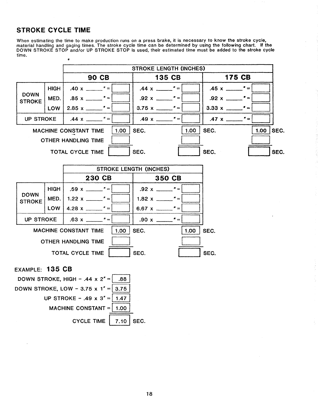
STROKE CYCLE TIME
When
estimating
the time
to
make
production
runs on a
press
brake.
it
is
necessary
to
know
the
stroke
cycle,
material
handling and gaging times. The
stroke
cycle
time
can
be
determined
by
using
the
following
charf.
If
the
DOWN
STROKE
STOP
and/or
UP
STROKE
STOP
is used.
their
estimated
time
must
be
added
to
the
stroke
cycle
time.
STROKE
LENGTH
(INCHES)
90
CB
135
CB
175CB
8=1
HIGH
.40
xI
.44
X
8=1
I
.45
X
-=1
I"
DOWN MED.
.85
x
-=1
I
..
92
X-=II
.92
X
-=1
I
STROKE
LOW
2.85
x-
=1
I
3.75
X
-=1
I
3.33
X
-=1
I
UP
STROKE
.44
x
8=1
I
.49
X-
=1
I
.47
X
-=1
I
MACHINE CONSTANT TIME
11.00
ISEC.
OTHER HANDLING TIME II
TOTAL
CYCLE
TIME fISEC.
11.00
ISEC.
I I
I ISEC.
11.00IsEc.
I I
I ISEC.
STROKE
LENGTH (INCHES)
230
CB
350
CB
HIGH
.59
x
-=1
I
.92
x
-=\
I
DOWN
STROKE
MED.
1.22
xn=II
1.82
X
n=1
I
LOW
4.28
X
n=1
I
6.67
x-=II
UP
STROKE
.63
x
8=1
I
.90
X-
=1
I
MACHINE CONSTANT TIME
11.00
ISEC.
OTHER HANDLING TIME II
TOTAL CYCLE TIME I ISEC.
EXAMPLE:
135
CB
DOWN
STROKE,
HIGH -
.44
x2n=I
.88
I
DOWN
STROKE,
LOW
-
3.75
x
1"
=
13.75
I
UP
STROKE
-
.49
X
3-
=
11.47
I
MACHINE CONSTANT =
11.00
I
CYCLE
TIME
~
SEC.
18
11.00
ISEC.
I I
IISEC.
This manual suits for next models
5
Table of contents
Other Cincinnati Industrial Equipment manuals


Popular Industrial Equipment manuals by other brands


ENERDOOR
ENERDOOR FINHRM5.080.M Operation manual

Chicago Dryer
Chicago Dryer AIR CHICAGO EXPRESS instruction manual

Asutec
Asutec ASMEL-410 operating manual

Carver
Carver MULTICLAMP Assembly instructions

Danfoss
Danfoss APP 11-13 instruction manual

Mitsubishi Electric
Mitsubishi Electric NZ2GFCF-D62PD2 user manual


