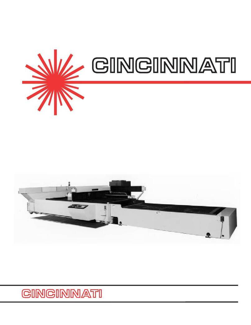
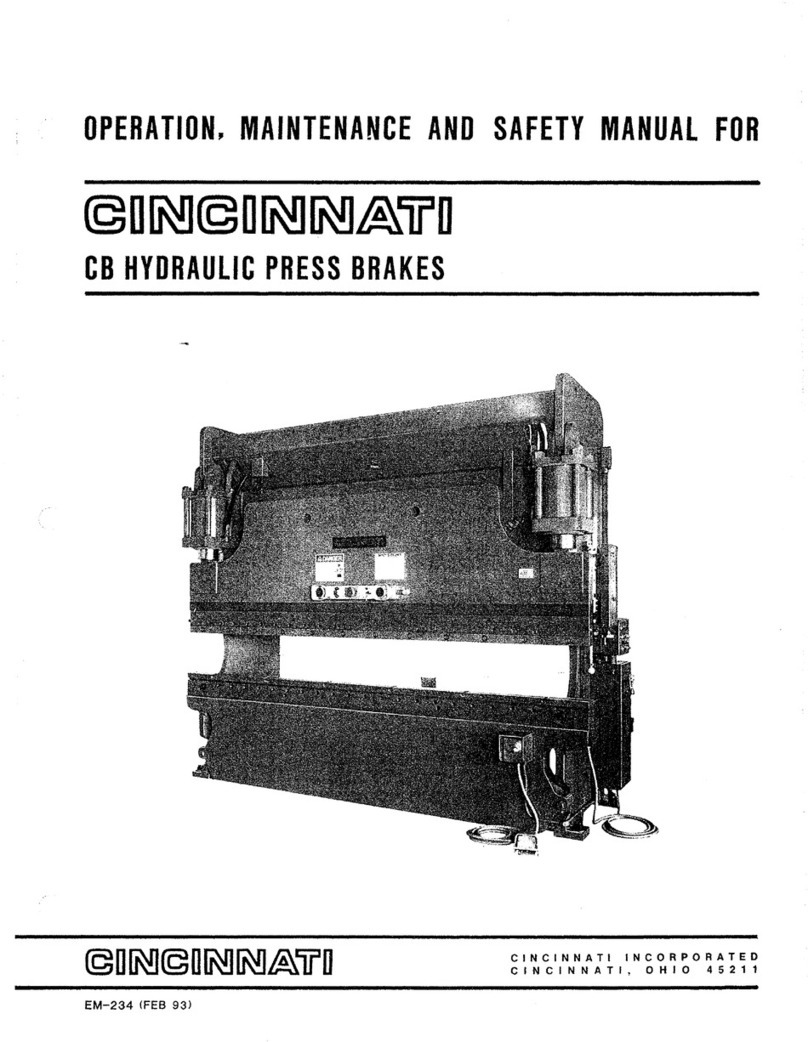
Cincinnati CL-7 Use and care manual

-
DPERATIDN
1
SAFETY
AND
MAINTENANCE
MANUAL
EM-355
(2
APR
92)
CNC
LASER
CENTER
CINCINNATI
INCORPORATED
CINCINNATI,
OHIO
45211


INTRODUCTION
SECTION 1
SECTION 2
SECTION 3
SECTION 4
SECTION 5
SECT~ON
6
~DENTIFICATION
~-----~-------------------
1-1
iNSTAllATION
liFTING
AND
MOVING
---------------------------
2-1
FOUNDATION
--------------------
_
---
_
----
___
----
2-1
ERECTION OF
MACHINE--------------------------
2-2
ERECTION OF
COMPONENTS--------------------
2-2
LEVELING----
___
---------
________
-----_----
__
---
2-2
iNITIAL
LUBRICATION----------------------------
2-2
ELECTRICAL CONNECTION______________________ 2-2
SAFETY
SAFETY
IS
EVERYONE'S
JOB
_____________________
3-1
HAZARDS----
______
------_-----_________________
3-4
ASSOCIATED
HAZARDS--------------------------
3-5
GAS STORAGE
----------------------------------
3-5
PRECAUTIONS
----------------------------------
3-8
SAFETY
SIGNS----------------------------------
3-8
SAFETY
GUIDELINES----------------------------
3-10
SAFETY MAINTENANCE CHI;:CK_______
~-----~----
3-iO
SPECIFICATIONS
DIMENSIONS
__
---
___
----
___
-----
___
---__________
4-1
SPECIFICATIONS ________________________
-----
__
_ 4-i
PIPING CONNECTIONS__________________________
4-1
EXTERNAL OPTICAL
ELEMENTS-----------------
4-2
GAS
REQUIREMENTS---------------------------
4-2
CONTOURING ACCURACY________________________ 4-3
AMBIENT TEMPERATURE
------------------------
4-4
CAPACITIES
_________
------_---
___
---
__
----
___
---
4-4
PRINCIPAL OF OPERATION
----------------------
4-4
SETaUP
AND
USE
LOADING
MATERIAL-----------------------------
5-1
GAGING
------
___________
---------------------
__
5-1
MACH~NE
CONTROlS
OPERATOR
CONTROL
CONSOLE _________________
6-1
REMOTE STATION
-------------------------------
6-6
lASER
HEAD
CONTROl
PANEL___________________ 6-7
COPYRIGHT©
1991
CINCINNATI INCORPORATED

SECTION 7
SECTION 8
SECTION 9
SECTION 10
OPERATION
DAILY
START-UP---------------------------------
7-1
NORMAL SHUTDOWN
---------------------------
7·1
LENS
CENTERING----------------------------·--
7·1
LENS
FOCAL
POINT
LOCATION
PROCEDURE
-----
7·2
ASSIST
GAS
PRESSURE
ADJUSTMENT-----------
7-5
COOLANT •
-----.-------------------.
__
••
-----
••
-7·5
POWER
CONTROL
------------------------------
7-6
PROGRAMMING
---------------------------------
7·9
SPECIAL
CODE
LIST-----------------------------
7·9
OPTIONS
BALL
TRANSFER
LOAD
STATION
-----------------
8-1
SCRAP
CONVEYOR
-----------------------------
8·1
HeNe
LASER-------------·-----------------------
8-1
NON-CONTACT
HEAD
---------------------------
8-1
PROGRAMMABLE ASSIST
GAS
PRESSURE-------
8·2
TOUCH
SENSOR
PROBE
-------------------------
8-2
MAINTENANCE AND ADJUSTMENTS
LUBRICATION
REQUIREMENTS-------------------
9-1
PALLET
DRIVE
MAINTENANCE
-------------------
9-1
OPTICS-----------------------------------------
9-2
BEAM
DELIVERY
ALIGNMENT---------------------
9·3
WHEN
REQUIRED------------------------
9·3
TOOLS
REQUIRED------------------------
9·4
COMPLETE
SYSTEM
ALIGNMENT----------
9-4
LASER
HEAD
ALIGNMENT
TO
MACHINE---- 9-4
X-AXIS
BEAM
ALIGNMENT----------------
9-5
Y-AXIS
BEAM
ALIGNMENT-----------------
9·6
Z-AXIS
ALIGNMENT-----------------------
9-7
FINAL ALIGNMENT
CHECK----------------
9-8
1/4
WAVE
PHASE
RETARDER
COOLING-----------
9-9
POWER
LEVEL CONTROL
••
----------------------
9-9
STAND
ALONE OPERATION-
LASER
HEAD--------
9-10
TROUBLESHOOTING
----------------------------
9-11
ALARM
AND
OPERATOR
MESSAGES
-------------
9-11
PREVENTATIVE
MAINTENANCE-------------------
9·13
SERVICE AND PARTS
SERVICE----------------------------------------
10-1
TRAINING---------------------------------------
10-1
ORDERING
REPAIR
PARTS-----------------------
10·1
RETURNING
PARTS
FOR
CREDIT-----------------
10·1
2

INTRODUCTION
CINCINNATI
CL-7
CNC
LASER
CENTER
The
Laser
Center
produces
two-dimensional
contoured
shapes
from fiat
matertal
by
mov-
ing
a
focussed
laser
beam
along
a
programmed
path.
The
beam
from
a
stationary
laser
resonator
is
directed
to
a
moving
lens
by
two
mirrors
mounted
on
a
moving
gantry.
The
workpiece
remains
stationary
while
a
narrow
strip
of
matertal
is
removed
along
the
path
made
by
the
lens.
Matertal
is
removed
by
vaporization
and
melting
where
the
lens
con-
centrates
laser
power
into
a
small
spot
on
the
workpiece.
Assist
gas
and
coolant
are
also
used
to
control
the
cutting
process.
The
mirrors
and
lens
are
positioned
by
the
gantry
to
produce
the
programmed
workpiece
geometry. A CNC
is
used
to
command
servo
dlives,
which
control
the
gantly
motion.
The
CNC
program
is
provided
by
the
user
and
also
includes
commands
to
specify fee-
drate,
laser
power,
assist
gas
and
coolant.
The
Laser
Center
is
equipped
'With
an
exhaust
system,
which
draws
air
down
from
the
cutting
area
to
assist
in
the
removal
of
process
by-products.
PART
QUALITY
The
follovving
factors
affect
part
quality:
.,
Machine
condition
e
Operator
ability
•
Setup
and
Programming
.,
Quality
and
type
of
material
CINCINNATI
machines
are
designed
to
be
rugged
and
durable.
However,
improper
adjustment
or
lack
of
maintenance
can
reduce
the
quality
of
parts
produced
on
the
machine.
The
quality
of
a
laser-cut
edge
depends
on
the
combination
of
a
uniform
laser
beam
of
adequate
power,
properly
focused
on
the
workpiece 'With
an
adequate
supply
of
the
correct
assist
gas,
traveling
at
a
speed
compatible
'With
the
material
removal
rate.
Uniform
beam
quality
and
power
level
are
most
influenced
by
the
alignment
and
cleanli-
ness
of
the
optical
elements
(internal
resonator
mirrors,
external
beam
delivery
mirrors
and
the
focusing lens).
Critical
manual
adjustments
are:
Lens
focal
point
location,
lens-to-nozzle
centertng,
and
the
assist
gas
pressure,
unless
programmable
gas
pressure
option
is
included.
Part
quality
depends
on
the
CNC
program
to
command
the
correct
combination
of
laser
power,
assist
gas,
feedrate
and
coolant
for
the
material
type
and
thickness
being
pro-
cessed.
Part
accuracy
depends
on
the
CNC
program
for
proper
use
of
kerf
width
compen-
sation
and
for selection
of
feedrate
'Within
radius
contouring
accuracy
limits.
Material
quality
can
affect
the
repeatability
of
process
parameters.
Matertal
which
has
uniform
composition
and
thickness
and
a
smooth,
clean
surface
'Will
minimize
variations
in
part
quality.


SECTION 1 IDENTIFICATION
CL-7
CNC
LASER
CENTER
FIGURE
1-1
1. LASER HEAD CONTROL
2. LASER WARNING LIGHT
3.
HIGH VOLTAGE WARNING
4.
LASER HEAD
5. Z-AXIS PROTECTIVE HOUSING
6.
CUTTING HEAD ASSEMBLY
7. GANTRY
8.
X-AXIS BEAM DELIVERY MIRROR BOX
9.
UPPER WORK PALLET
10. X-AXIS GUIDE AND X-AXIS BALLSCREW
(Covered by bellows)
11.
X-AXIS BEAM TUBE
12. SUPPORT GRID
13. LOWER WORK PALLET
14. FEED HOLD BUTTON (Pallet drive adjustment
located underneath plate on both sides of frame)
15. LOAD STATION PENDANT
16. LOAD FRAME
17. FUME/COOLANT
PAN
18. OPERATOR'S MANUAL
19. SAFETY MAT
20. OPERATOR CONTROL CONSOLE
21. MAIN FRAME
1-1

22. ASSIST GAS PRESSURE SWITCH
23. Z-AXIS DRIVE MOTOR (Behind bellows)
24. MATERIAL CONTACT SWITCH
25. COUNTERBALANCE SPRING
26. PROGRAMMABLE ASSIST GAS
27. 5.0" FOCAL LENGTHLENS HOLDER
28. BLANK LENS HOLDER
29. LENS PURGE GAS LINE
30. LENS COOLING WATER LINE
31. TOUCH PROBE
32. MAGNETIC BREAKAWAY COUPLING
33. COOLANT LINE (Cutting
fli.l,id)
34. HINGED COVER (Shown removed)
35. MATERIAL FOLLOWER/ADJUSTING
RING
FIGURE
1-2
1-2

FIGURE
1-3
36. FUME DUCT (Exits to axial flow fan attached to 41. PALLET DRIVE MOTORS (2)
outside of frame) 42. OPTICS COOLANT FILTERS (2)
37. PALLET DRIVE CABLE 43. FUME PLENUM
38. X-AXIS SERVO MOTOR 44. SCRAP TRAY
39. SCRAP CONVEYORS (Optional) 45. COOLANT PUMP AND RESERVOIR
40. X-AXIS OVERTRAVEL BUMPER 46. COOLANT RESERVOIR FILTER
1-3


LIFTING &MOVING
Machine
weights
as
shipped
are
approximately:
MAINFRAME
LOAD
FRAME
5 X
10-
22,000
lbs.
8,000
lbs.
(9,977
Kg.)
(3,628
kg.)
6 X
12-
25,000
lbs.
9,500
lbs.
(11,338
kg.)
(4,308
kg.)
Variations
of
plus
or
minus
500
pounds
(227
Kg)
from
these
figures
are
possible,
depending
on
optional
equipment
installed.
The
Main
Frame
is
lifted
by
using
the
four
lifting
locations
provided.
There
are
two
1-l/4"
diameter
holes
located
in
front
of
the
Resonator.
These
holes
are
for
standard
lifting
devises.
There
are
also
two
1
"-8 UNC
tapped
holes
for swivel clevises
located
at
the
front
of
the
Main
Frame.
See
Figure
2-1.
CAUTION
WHEN
liFTING
MAIN FRAME BE SURE THAT
SWIVEL
ClEVISES
(C.I. PART #525462) ARE
INSTAllED
AS MEANS TO
liFT
THE
FRONT
(lOAD
FRAME END). USING
AN
EYEBOlT
OR
ANY
OTHER
DEVICE
NOT
DESIGNED
FOR
EXCESSIVE SIDE
lOADS
COUlD
RESULT IN
SERIOUS INJURY
OR
DEATH
TO
BYSTANDERS
AND/OR CAUSE EXTENSIVE DAMAGE TO
THE
MAIN FRAME AND RESONATOR.
FIGURE
2~1
=
lifting
Main Frame
IMPORTANT:
Extreme
cue
must
be
taken
not
to
subject
the
machine
to
shock
loads.
The
machine
must
be
lifted
and.
set
down
gently.
2-1
The
Load
Frame
is
lifted
by
placing
four
chain
hooks
at
each
of
the
four
outer
machine
corners.
The
chain
hooks
are
hooked-in
the
access
holes
at
these
locations.
See
Figure
2-2.
FIGURE 2=2-
lifting
load
Frame
FOUNDATION
This
section
applies
only
to
machines
installed
in
an
area
not
affected
by
shock
inducing
equipment,
such
as
punch
presses,
turret
punches,
etc.
Installations
involving
this
type
of
equipment
in
close
proximity
to
the
machine
require
special
considerations
and
CINCINNATI INCORPORATED
must
be
consulted.
A
Foundation
Plan
drawing
is
provided
when
the
machine
is
ordered.
This
drawing
will
provide
the
user
with
~11
the
detailed
information
required
to
locate
the
equipment
and
the
eight
machine
anchors.
The
eight
anchor
locations,
each
approx-
imately
6" x 6"
(152
x
152
rum),
should
be
prepared
by
the
customer
prior
to
arrival
of
the
equipment.
These
eight
pads
must
be
pre-leveled
to lie
in
the
same
plane
within
.50
inches
(12.7 mm);
and
eight
anchor
holes
should
be
drilled
as
specified
on
Foundation
Plan
drawing.
Shims
for final leveling,
anchors,
studs,
nuts
and
isolation
pads
are
provided
by
CINCINNATI
INCORPORATED.
Optional
wedge
type
adjustable
mounts
are
available.
These
provide
a
secure
footing
for
the
machine,
limited
isolation
from
shock
and
will
considerably
speed
the
installation
process.
Floor
should
be
concrete,
have
a
minimum
thick-
ness
of
6
inches
(
152
mm),
and
be
free
from
cracks.

ERECTION OF MACHINE
After
setting
the
machine
on
the
anchor
studs,
place
washers
and
nuts
on
studs
but
do
not
tighten.
Erection
consists
of
the
following
steps:
l.
Be
sure
lifting
devises
are
removed.
2.
Remove
all
steel
banding
and
protective
wrappings.
3.
Install
fume
fan
and
duct
connecting
to
fume
pan
with
flange
and
fasteners
provided.
Be
sure
to
seal
connection
with
a
bead
of
RTV silicone.
Make
the
electrical
connection
to
the
fan
drive
motor
with
wiring
provided.
4.
Install
the
operator's
control
console
with
the
fasteners
provided.
Refer
to
Electrical
Section
for
connection.
5.
Refer
to
Laser
Manufacturer's
manual
provided
for
preparation
of
the
laser
resonator.
ERECTION OF COMPONENTS
The
water
chiller
is
a free-standing
unit
requiring only
floor
support.
It
is
connected
at
a
central
location
with
hoses
furnished
with
machine
(for
chiller
location
shown
on
Foundation
Plan)
on
the
drive side
at
the
laser
end
of
the
frame. The chiller
should
be
positioned
as
shown
on
the
Foundation
Plan drawing.
Consult
CINCINNATI
INCORPORATED
if
an
alternative chiller location
is
required.
After
chiller
(and
transformer)
installation,
wiring
and
final leveling,
the
safety
cable
on
the
drive
side
of
the
machine
should
be
installed
as
shown
on
the
Foundation
Plan
drawing.
Likewise,
the
safety
mats
must
be
located
and
connected.
LEVELING
Leveling
adjustments
are
made
using
jackscrews,
which
are
accessible
through
openings
in
the
frame
above
each
of
eight
mounting
pads.
Slotted
shims
are
inserted
between
the
machine
foot
and
the
steel
spacer
block
as
shown
on
the
Foundation
Plan
drawing.
After
shims
are
inserted,
jack
screws
are
to
be
backed-off
or
removed.
On
machines
equipped
with
optional
adjustable
wedge
type
mounts,
adjustments
are
made
using
the
wedge
screw.
Shimming
is
eliminated
and
no
jackscrew
or
spacer
blocks
are
required.
The
procedure
for
leveling
is
described
below:
PRELIMINARY
lEVELING
l.
Cross-leveling
is
checked
by
placing
a
precision
level
on
the
machined
surface
on
the
top
of
the
main
frame
end
plate
nearest
the
laser
head,
and
using
the
jackscrews
and
shims
provided
to
make
adjustments.
2.
Longitudinal
level
is
checked
on
the
top
of
the
X-Axis
guide
way.
Adjust
as
described
above.
FINAl lEVEliNG
1. Use a 15"
precision
spirit
level
with
a
sensitivity
of
.0005"/ft.
2.
Place
the
level
on
the
top
of
the
gantry
and
position
the
gantry
at
X=
0.
3.
The
top
of
the
gantry
is
not
machined.
Therefore,
it
will
be
necessary
to
shim
one
or
both
ends
of
the
level
to
establish
a
reference
reading
and
make
the
level
sit
solidly
in
place.
Paper
shims
can
be
used
for
this
purpose.
4.
Observe
the
position
of
the
bubble
while
slowly
jogging
the
gantry
from
X = 0
to
X =
120.
Maximum
deviation
is
one
division
of
the
level
(.0005/ft.) from
end-to-end.
This
ensures
that
the
frame
is
not
in
a
twist.
Make
adjustments
as
described
above,
using
jackscrews
to
add
or
remove
shims.
5.
When
Step
4
is
complete,
lightly
tighten
anchor
nuts
and
recheck
level
as
specified
in
Step
4.
6.
Tighten
the
anchor
nuts
with
light
hand
pressure
on
the
wrench
so
as
not
to
crush
the
stud
isolation
washer.
Secure
the
anchor
nuts
with
locknuts
provided
as
shown
on
the
Foundation
Plan
drawing.
7.
Repeat
Step
4
as
a final level
check.
INITIAl lUBRICATION
Machines
are
fully
lubricated
before
leaving
the
factory.
Unusual
circumstances,
such
as
storage
for
more
than
one
month
from
shipment
date
will
require
initial
lubrication
per
chart
in
Section
9
of
this
manual.
ElECTRICAL
CONNECTION
Each
Laser
customer
is
supplied
a
complete
set
of
Foundation
Plan
drawings
prior
to
machine
shipment.
The
The
electrical
load
requirements
and
connection
points
are
called
out
on
these

drawings.
Be
certain
that
a
suitably
sized
wire
is
brought
to
the
main
disconnect
and
the
proper
voltage
is
supplied.
The
CL-7
Laser
standard
electrical
input
is
460
volt, 3
phase
and
50/60
hertz.
The
machine
must
be
properly
grounded
in
accordance
with
National
Electric
Code
NFPA
70,
Sections
250-81,
83,84
and
89.
CINCINNATI INCORPORATED
recommends
using
an
individual
electrode
per
Section
250-83
(C)
to
avoid
interference
from
other
equipment.
Do
not
start
the·
machine
until
thoroughly
reading
the
SAFETY
section
of
this
manual
and
a
CINCINNATI INCORPORATED
Service
Represent-
ative
is
present.


SAFETY IS EVERYONE•s
JOB
The
CINCINNATI CNC
Laser
Center
manufactured
by
CINCINNATI INCORPORATED
has
been
designed
to
meet
the
highest
order
of
reliability
and
ease
of
operator
use.
This
system
has
been
certified
under
Federal
Regulations
21 CFR,
subpart
J,
as
a
Class
IV
Laser
product
as
required
by
the
Federal
Radiation
Control
for
Health
and
Safety
Act
of
1968.
This
certification
is
on
file
with
the
Food
and
Drug
Administration
Center
for Devices
and
Radiological
Health
Division,
Laser
Products
Section,
Silver
Springs,
Maryland
20910.
CINCINNATI INCORPORATED
recommends
the
cus-
tomer
read
and
understand
the
requirements
of
the
American
National
Standard
for
safe
use
of
Lasers,
ANSI
Z136.l.
This
is
available
from
the
American
National
Standards
Institute,
1430
Broadway, New
York,
NewYork
10018.
For
additional
safety
information
we
recommend:
•
Securing
applicable
safety
data
from
the
National
Safety
Council,
425
North
Michigan
Avenue,
Chicago,
Illinois
60611
and
Laser
Institute
of
America,
5151
Monroe
Street,
Toledo,
Ohio
42623.
•
Determining
your
responsibilities
under
your
state
and
local
safety
codes.
"
Requesting
assistance
from
the
loss
prevention
department
of
your
workmen's
compensation
carrier.
Personnel
responsible
for
your
Laser
Center
opera-
tor
training
program,
maintenance,
and
manufac-
turing
operations
must
read
and
understand
this
safety
section
and
operator's
manual.
No
one
should
set-up,
operate
or
maintain
this
Laser
Center
until
they
thoroughly
understand
it
and
know
how
to
do
their
job
safely.
INTRODUCTION
TO
LASER SAFETY
The
laser
is
an
intense,
highly
directional
beam
of
light
that,
if
directed,
reflected
or
focused
upon
an
object,
will
be
partially
absorbed.
This
raises
the
temperature
of
the
surface
and/
or
the
interior
of
the
object,
which
can
potentially
cause
an
alteration
or
deformation
of
the
material.
These
properties,
which
have
been
applied
to
laser
material
process-
ing,
can
also
cause
adverse
biological
effects
in
human
tissue.
The
CINCINNATI CNC
Laser
Center
operates
in
the
far-infrared
region,
which
:i.s
invisible
and
has
high
heat
energy.
The
beam
emitted
has
a
wavelength
of
10.6
~m (micrometers).
A BRIEF DiSCUSSION
ON
RADIATION
Radiation
is
defmed
in
Webster's
as
"energy
radiated
in
the
form
of
waves
or
particles".
Radiation
is
a
form
of
energy
emitted
from
a
wide
range
of
sources,
some
man-made
and
some
natural.
The
electromagnetic
spectrum
covers
those
forms
of
energy
with
wavelengths
of
approximately
10-11
meters
to
107
meters.
That
corresponds
to
frequen-
cies
of
approximately
1022
hertz
to
approximately
1000
hertz.
All
forms
of
electromagnetic
radiation
travel
at
the
speed
of
light,
but
at
differing
frequencies.
The
wavelength
of
such
a
wave
is
inversely
proportional
to
the
frequency,
and
often
a
particular
type
of
radi-
ation
is·
described
in
terms
of
its
wavelength
rather
than
its
frequency.
The
energy
transmitted
by
such
radiation
is
also
related
to
its
frequency
-
the
higher
the
frequency,
the
greater
the
energy.
The
energy
of.radiation
tends
to
interfere
with
the
internal
energy
that
holds
atoms
together
as
molecules.
If
the
energy
of
a
ray
of
radiation
is
great
enough,
it
will
attract
electrons
away
from
an
atom
or
add
additional
elec-
trons
to
it.
Radiation
that
lacks
the
energy
to
deform
atoms,
(non-ionizing)
radiation,
can
still
cause
bodily
harm
by
raising
the
temperature
of
the
body
tissue
the
radiation
contacts
with
the
energy
it
imparts.
If
this
tissue
is
the
hardened,
dead-cell
tissue
of
the
outer
skin,
it
does
little
harm.
It
may
produce
reddening
of
the
tissue
and
mild
soreness.
However,
if
that
same
radiation
energy
gets
inside
the
body
to
less
well-protected
tisSIUe,
the
tissue
may
not
only
be
heated,
but
may
become
damaged
as
well.
The
eyes
are
also
very
susceptible
to
radiation
energy.
The
cells
of
the
cornea
and
the
retina
are
easily
destroyed
and
must
always
be
protected
from
radi-
ated
energy.
Ordinary
industrial
type
safety
glasses
will
provide
this
protection.
Figure
3-1
is
a
chart
of
that
portion
of
the
electro-
magnetic
spectrum
pertinent
to
our
discussion.
The
area
the
CINCINNATI
CL-7
LASER
operates
in
is
located
between
3x10⁻⁵
and
3x10⁻⁶
meter
wave-
length.
This
brief
introduction
has
been
prepared
to
alleviate
any
unwarranted
worries
regarding
laser
radiation
safety.
SAFETY STANDARDS
Research
studies,
along
with
an
understanding
of
the
hazards
of
sunlight
and
conventional,
man-
made
light
sources
have
also
permitted
scientists
to
establish
safe
exposure
limits
for
nearly
all
types
of
laser
radiation.
These
limits
are
generally
referred
to

FREQUENCY WAVELENGTH
(hertz) (meters)
-
1022
3x1
0"
14
-
-
1021
3x1
0"
13
-
~Gamma
-
1020
3x1
0"
12
-rays
-
1019
3x1o-
11
-<
X-rays
-
1018
3x1
0"
10
-Ultraviolet
-
1017
3x1o·9 -rays
-
1016
3x1o·8 -
Visible light ·(380-780 {
nanometers wavelength) · _
1015
3x1o·7
-"""
I
-
1014
3x1o·6 -
~INCINNAll
Lasers
-
~Infrared
CNCLASER
--.·J
-
1013
3x1o·5 -rays
-
1012
3x1o·4 -
-
1011
3x1o·3
_.,;
-
1010
3x1o·2 -
~Microwave
-109
3x1
o·
1 -
FM
broadcast band
-(
-108 3 -
~,
Radio -frequency
-107 30 -(RF) waves
AM broadcast band
-{
(535-1605 kilohertz) -106 3x10² -
-105 3x10³ -
Telephone
{
~
104 3x10⁴ -
103 3x10⁵
f-
Commercial electric
--=
100 3x10⁶
1-
power (60 hertz) -10 3x10⁷
.__
Figure
3-1
-Electromagnetic spectrum
3-2

as
Maximum
Permissible
Exposures
(MPE's)
by
laser
safety
specialists.
In
many
cases,
it
is
unnec-
essary
to
make
use
of
MPE's
directly.
The
past
experience
gained
in
millions
of
hours
of
laser
use
in
the
laboratory
and
in
industry
has
permitted
the
development
of
a
system
of
laser
hazard
categories.
Each
laser
is
placed
into
one
of
at
least
four
sepa-
rate
classes,
or
risk
categories.
The
safety
measures
to
reduce
or
eliminate
accidents
depend
u_pon
which
class
of
laser
is
being
used.
There
are
a
variety
of
laser
safety
standards.
These
include
regulations
of
the
Federal
Govemment,
and
of
several
state
and
local
govemments.
Additionally
there
are
non-regulatory
standards,
such
as
the
ones
of
the
American
National
Standards
Institute
(ANSI)
and
of
the
American
Conference
of
Governmental
Industrial
Hygienists
(ACGIH).
On
the
international
scene,
the
World
Health
Organization
(WHO)
has
laser
safety guidelines,
and
the
International
Electrotechnical
Commission
(IEC)
has
been
developing
laser
safety
standards.
Of
the
standards
that
apply
to
users,
the
ANSI
standard
Zl36.1
is
probably
the
most
important
and
most
often
quoted.
It
provides
information
on
how
to
classify
lasers
for
safety,
laser
safety
calculations
and
measurements,
and
laser
hazard
control
mea-
sures.
LASER HAZARD CLASSIFICATION
As
previously
indicated,
laser
systems
can
be
grouped
into
at
least
four
primary
categories
to
indicate
relative
potential
risk:
Class
I - A
class
I
laser
is
considered
safe
based
upon
current
medical
knowledge.
This
class
includes
all
lasers
or
laser
systems
which
can-
not
emit
levels
of
optical
radiation
above
the
exposure
limits
for
the
eye
under
any
exposure
conditions
inherent
in
the
design
of
the
laser
product.
There
may
be
a
more
hazardous
laser
embedded
in
the
enclosure
of
the
Class
I
prod-
uct,
but
no
harmful
laser
radiation
can
escape
the
enclosure.
Class
II
- A
class
II
laser
or
laser
system
must
emit
a
visible
laser
beam,
which
by
its
very
bright
nature
will
be
too
dazzling
to
stare
into.
Momentary
viewing
is
not
considered
hazardous
since
the
upper
radiant
power limit
on
this
type
of
device
is
1 mW
which
corresponds
to
the
total
beam
power
entering
the
eye for a
momentary
exposure
of
0.25
second
that
is
just
safe
(i.e.,
the
MPE for a
0.25
second
exposure).
Class
III - A
class
III
laser
or
laser
system
can
emit
any
wavelength,
but
it
cannot
produce
a
haz-
ardous
diffuse
reflection
unless
focused
or
viewed for
extended
periods
at
close
range.
It
is
also
not
considered
a fire
hazard
or
a
serious
skin
hazard.
Any
CW
(continuous
wave)
laser
3-3
that
is
not
class
I
or
class
II
is
a
class
III
device
if
its
output
power
is
0.5
W
or
less.
Since
the
output
beam
of
such
a
laser
is
definitely
haz-
ardous
for
intrabeam
viewing,
control
measures
center
on
eliminating
this
possibility.
Class
N -A
class
N
laser
or
laser
system
is
any
that
exceeds
the
output
limits
(Accessible
Emission
Limits, AEL's)
of
a
class
III
device.
As
would
be
expected,
these
lasers
inay
be
either
a
fire
and
skin
hazard/
or
a diffuse reflection
haz-
ard.
Very
stringent
control
measures
are
required
for a
class
IV
laser
or
laser
system.
CONTROL MEASURES
The
CINCINNATI
CNC
Laser
Center
has
been
designed
and
manufactured
using
the
highest
engi-
neering
control
measures
practical,
however,
even
these
high
standards
have
limitations.
Laser
safety
requirements
call for
administrative
and
procedural
controls
to
be
incorporated
in
the
use
of
lasers
in
order
tQ
minimize
or
eliminate
the
potential
of
per-
sonal
inju:ry
during
laser
operation.
The
position
of
Laser
Safety
O.tficer
(LSO)
must
be
established
within
the
management
organization
of
a
company
using
a
laser
cutting
machine.
This
per-
son
has
the
responsibility
and
authority
to
monitor
and
enforce
the
control
of
laser
hazards.
He
or
she
should
have
the
knowledge
to
effectively
evaluate
and
control
hazards
involved
in
laser
cutting.
The
LSO
is
responsible
for
requiring
written
standard
operating,
maintenance
and
service
procedures
for
the
laser
center.
These
procedures
should
be
kept
at
the
laser
center
for reference
by
operating
main-
tenance
and
service
personnel.
Continued
education
and
training
for
operating
maintenance
and
service
personnel
is
mandatory
for
an
adequate
laser
safety
program
to
exist.
The
Laser
Safety
Officer
should
see
to
it
that
personnel
involved
in
various
aspects
of
laser
operation
have
been
trained
to
a level
commensurate
with
the
level
of
potential
hazards
to
which
they
may
be
exposed.
OPERATING
PER~NNEL
These
people
are
responsible
for
the
productive
use
of
the
laser
cutting
center
over
the
full
range
of
its
intended
function.
These
persons
should
be
thor-
oughly
familiar
with
all
operating
controls,
adjust-
ments
and
hazards
associated
with
their
function.
MAINTENANCE PERSONNEL
These
individuals
are
responsible
and
should
be
thoroughly
trained
in
the
performance
of
adjust-
ments
or
procedures
specified
in
the
User
Information
manuals
provided
by
the
manufacturer
of
the
laser
center.
The
functions
performed
are
to
insure
the
intended
performance
of
the
laser
center
is
realized.

SERVICE PERSONNEL
These
individuals
are
responsible
for
the
perfor-
mance
of
procedures
and
adjustments
described
in
the
manufacturer's
service
manual.
The
duties
of
a
service
person
requires
a
higher
level
of
training
and
education
than
that
of
the
maintenance
func-
tion, however, a service individual
does
not
neces-
sarily
include
the
duties
or
responsibilities
of
a
maintenance
person.
A
strong
commitment
from
management
must
exist
in
order
for
an
effective
safety
program
to
be
estab-
lished
with
personnel
involved
in
the
use
of
the
CINCINNATI
CNC
Laser
Center. Additional
informa-
tion
concerning
this
topic
can
be
located
in
the
American
National
Standard
Z136.1-1986.
Refer
to
Appendix
D
of
this
standard
for a
guide
for organiz-
ing
and
implementing
a
laser
safety
and
training
program.
EXPLANATION
OF
LASER RADIATION
Light
is
a form
of
energy
that
is
released
from indi-
vidual
atoms
or
molecules
in
a
substance.
To
understand
how
a
laser
works,
it
is
necessary
to
know
something
about
the
nature
of
atoms
and
how
they
interact
with
light
and
other
forms
of
energy.
Every
atom
is
a
storehouse
of
energy.
The
amount
of
energy
in
an
atom
depends
in
part
on
the
motion
of
the
electrons
that
orbit
the
atom's
nucleus.
When
an
atom
absorbs
energy,
the
energy
levels
of
the
electrons
increase,
and
the
atom
is
said
to
be
excit-
ed.
The
atoms
of a
substance
become excited
when
they
absorb
heat,
light,
or
other
forms
of
energy
that
pass
through
the
substance.
An
excited
atom
can
return
to
its
normal
energy
level
by
releasing
its
excess
energy
in
the
form
of
light.
This
release
of
light
is called
spontaneous
emission.
In
spontaneous
emission,
excited
atoms
release
light
irregularly.
As
a
result,
the
light
has
different
frequencies, different
phases,
and
travels
in
differ-
ent
directions.
Light
released
in
this
way
is
called
incoherent
light.
Such
light
is
produced
by
the
sun
and
by
ordinary
electric
light
bulbs;
Excited
atoms
also
may
release
light systematically.
This
kind
of
release, called
stimulated
emission,
is
the
main
process
that
takes
place
in
a
laser.
Stimulated
emission
occurs
when
the
energy
released
from
one
atom
interacts
with
another
atom
that
is
still excited.
The
interaction
stimulates
the
excited
atom
into
releasing
its
own
energy
as
light.
Most
of
the
light
produced
by
stimulated
emission
has
the
same
frequency
and
same
phase
as
the
stimulating
light.
It
also
travels
in
the
saine.
direc-
tion,
and
so
it
combines
with
and
amplifies
the
trig-
gering
light.
Such
light
is
called
coherent
radiation.
3-4
LASER TYPES.
There
are
three
major
kinds
of
lasers
based
on
their
lasing
medium:
solid
lasers,
gas
lasers,
and
liquid
lasers.
The
CINCINNATI
CNC
Laser
Center
model CL-7
is
a
gas
type laser.
Gas
lasers
use
a
gas
or
a
mixture
of
gases
as
their
light-amplifying·
substance.
In
most
cases,
the
gas
is
contained
in
a
glass
or
quartz
tube
from
one
to
three
feet (30
to
91
centimeters)
long.
Such
gas
lasers
have
been
built
in
glass
tubes
mea-
suring
up
to
30
feet
(9
meters)
in
length.
Gas
lasers
have
several
power
sources,
including
chemical
reactions,
electric
current,
electron
beams,
and
ultraviolet
rays.
Most
gas
lasers,
produce
a
continu-
ous
beam
of
light.
They
also
can
produce
beams
of
higher
average
power
than
solid
lasers
can.
They
can
do
so
because
they
are
cooled
by
the
gas
as
it
flows
through
the
tube.
The
light
from a
gas
laser
has
a
narrower
frequency
range
than
the
light
from
a solid laser.
As
an
option, a
second
laser
can
be
added
to
the
CL-7 CNC
Laser
Center.
This
is
the
HeNe
laser,
which
is
a
gas
laser
using
helium-neon
gases
to
produce
a
visible
red
beam.
Due
to
the
visible
nature
of
this
beam
and
its
power
level,
it
is
desig-
nated
as
a
Class
II
laser
product.
Class
II
levels
of
laser
radiation
are
considered
a
chronic
viewing
hazard
and
thus
the
warning
not
to
stare
into
the
red
beam
as
given
on
our
warning
sign.
HAZARDS
EVE HAZARDS
The
eye
hazards
represent
a
potential
for
injury
to
several different
parts
of
the
eye, generally
depend-
ing
upon
which
eye
part
absorbs
the
most
radiant
energy.
Laser
radiation
in
the
far-infrared
region
with
wave
lengths
of
3J.Im
to
1 millimeter will
be
absorbed
in
the
front
surface
of
the
eye.
Thus,
if
the
eye
is
not
protected,
it
may
receive
damage
to
the
cornea
and
lens
from
direct
or
reflected
laser
beam
exposure.
Therefore, eye
protection
must
be
worn
by
all
oper-
ation,
maintenance
and
service
personnel
while
working
at
the
CINCINNATI CNC
Laser
Center.
The
type
and
style
of
eye
protection
to
use
should
be
worked
out
with
the
supplier
of
your
shop
eye
pro-
tection
program.
In
general,
the
normal
safety
glasses
with
side
shields
used
in
metal
working
shops
will
provide all
the
protection
necessary.
It
is
the
user's
responsibility
to
establish
and
enforce
an
eye
protection
program.
SKIN HAZARDS
Laser
radiation
striking
the
skin
is
reflected,
absorbed,
and
transmitted;
the
percentage
of
each
depends
upon
the
characteristics
of
the
skin
at
the
II

wavelengths
of
concern.
Effects
on
the
skin
from
absorbed
radiation
may
vary
from mild
redness
to
blistering
and/
or
charring,
depending
upon
the
total
energy
absorbed
and
the
rate
at
which
it
is
absorbed.
Unnecessary
exposure
of
the
skin
to
laser
radiation
should
be
avoided regardless
of
the
level
of
radiant
energy.
The
CINCINNATI
CNC Laser
Center
has
beeri
tested
and
found
to
have
no
detectable
x-ray
emissions
and
related
hazards.
In
general,
the
hazards
pre-
sented
by
the
CINCINNATI
CNC
Laser
Center,
which
operates
in
the
far-infrared.(invisible light) region,
will
be
severe
burns,
lacerations
and
possible
amputation
if
members
of
the
body
come
in
contact
with
the
direct
beam
or
close to reflected
beams
of
high
energy.
The
design
of
the
Laser
Center
pro-
vides engineered protection from
these
hazards
for
personnel
while properly
using
this
equipment. This
basic
design
should
not
be
altered
or
modified
in
any
manner.
ASSOCIATED HAZARDS
ELECTRICAL
Because
of
the
high
electrical energies
used
to gen-
erate
the
laser
beam
in
the
CINCINNATI
CNC
Laser
Center,
electrocution
hazards
are
possibly
a
far
greater
danger
to
personnel
than
those
of
the
laser
beam
itself.
This
is
why
no
access
to
high
electrical
energy
is
possible
without
going
through
a
safety
interlocked door
or
pqnel. Before
any
maintenance
or
service
is
undertaken,
you
should
ensure
that
the
laser
component
has
been
isolated
from
the
electrical service
and
all
other
precautions
taken
as
prescribed
in
this
manual
and
the
other
component
manuals
provided.
CAUTION
HIGH VOLTAGE OF UP TO 30,000 VOLTS
IS
PRE·
SENT
IN
THE LASER HEAD AND POWER SUPPLY
CABINET. CONTACT WITH VOLTAGE CARRYING
CONDUCTORS IS NOT NECESSARY, AS ENERGY
AT THIS POTENTIAL CAN JUMP TO A CLOSE
BODY
AT
GROUND POTENTIAL, SUCH
AS
YOUR·
SELF, CAUSING IMMEDIATE DEATH. DO NOT
ENTER ANY HIGH VOLTAGE
AREA
WITHOUT
FIRST
DISCONNECTING POWER. REFER TO
LASER MANUFACTURER'S SERVICE MANUAL
BEFORE ENTERING THIS CABINET.
FIRE
Fire
hazard
is
present
in
the
processing
area
through
interaction
with
the
laser
beam
and
materi-
als
present
in
the
work
area. Additional fire
hazards
exist
in
the
electrical controls enclosed
in
the
Laser
Center
cabinets. Appropriate fire
equipment
should
3-5
be
available
and
the
purpose
of
such
equipment
should
be
understood
by
operating
per~onnel.
This
equipment
should
be
provided to
extinguish
or
con-
trol
small fires only. Follow
basic
fire fighting proce-
dures.
FUME AND DUST
WARNING
-POISONOUS
FUMEs
MAY
BE
FORMED
BY
LASER CUTIING. DO NOT BREATHE FUMES.
Use
only
with
adequate
ventilation
or
respirators.
The
ventilation
requirements
should
be
determined
by
a professional qualified
to
assess
ventilation con-
trol
requirements.
The
CL-7 Laser
is
equipped
with
an
exhaust
system
that
draw$
air
down from
the
cutting
surface.
The
optimal
exhaust
rate
for
your
specific
application
of
the
CL-7 Laser
should
be
determined
by
a profes-
sional
qualified
to
assess
ventilation
systems.
The
OSHA-required Material Safety
Data
Sheet
for
the
material
being
processed
should
be
reviewed to
aid
in
determining
the
nature
and
composition
of
the
fumes being released.
The
need
and
subsequent
design
of
a device
to
eliminate
poisonous
emissions
from
the
ventilation
exhaust
should
be
made
by
a
professional
qualified
to
evaluate
control
devices.
Finally,
the
presence
of
personnel
exposures
to
fumes
should
be
determined
by
a professional qual-
ified to
evaluate
workplace
exposures
to
chemical
and
physical
hazards.
Operation
of
the
CL-7
Laser
and
ventilation
sys-
tem/control
device
may
subject
you
to
local
state
and
federal environmental
and
occupational protec-
tion
laws
and
regulations. A professional qualified
to
assess
environmental
and
occupational
protec-
tion
laws
and
regulations
must
be
consulted
before
the
CL-7 Laser
is
installed
and
operated.
'GAS STORAGE
Various
gases
are
used
in
the
laser
cutting
process
to
assist
in
the
actual
cutting
or
to
perform
auxil-
iary
functions.
The
gases
most
commonly
used
are
oxygen, nitrogen,
carbon
dioxide,
helium,
and
com-
pressed
air.
These
gases
are
commonly·available
in
compressed
gas
cylinders.
Oxygen,
nitrogen,
and
helium
are
also
available
as
cryogenic
liquid.
Carbon
dioxide, while
not
classified
as
a
c:ry"Ogenic,
is
also widely available
in
liquid form.
The
discus-
sion
below
will
address
safety
consideration
when
storing
and
handling
compressed
gas
cylinders.
Later
in
this
section
will
be
a
discussion
on
safety
precautions
concerning
cryogenic liquids.
COMPRESSED
GAS
CYLINDERS
HANDLING
Serious
accidents
may
result
from
the
misuse,
abuse,
or
mishandling
of
compressed
gas
cylinders.
Workers
assigned
to
the
handling
of
cylinders
under

pressure
should
be
properly
~rained
and
should
work
only
under
competent
supervision.
Observing
a few
basic
rules
will
help
control
hazards
in.
the
handling
of
compressed
gas
cylinders.
.,
Because
of
their
shape,
smooth
surface,
and
weight,
cylinders
are
difficult
to
carry
by
hand.
Cylinders
may
be
rolled
on
their
bottom
edge
but
never
dragged.
Cylinders
weighing
more
than
40
pounds
(18.2 kg) (total)
shall
be
transported
on
a
hand
or
motorized
truck,
suitably
secured
to
keep
them
from falling.
..
Do
not
lift
compressed
gas
cylinders
with
an
electromagnet.
Where
cylinders
must·
be
handled
by
a
crane
or
derrick,
carry
them
in
a
cradle
or
suitable
platform
and
take
extreme
care
that
they
are
not
dropped
or
bumped.
Do
not
use
slings.
"
Do
not
drop
cylinders
or
let
them
strike
each
other
violently.
"'
Do
not
use
cylinders
for rollers,
supports,
or
any
purpose
other
than
to
contain
gas.
..
Do
not
tamper
with
safety
devices
in
valves
or
on
cylinders.
"
When
empty,
cylinders
are
to
be
returned
to
the
vendor,
mark
them
EMPTY
or
MT
with
chalk.
Close
the
valves
and
replace
the
valve
protection
caps,
if
the
cylinder
is
designed
to
accept
a
cap.
.,
Always
consider
cylinders
as
being
full
and
han-
dle
them
with
corresponding
care.
Accidents
have
resulted
when
containers
under
partial
pressure
were
thought
to
be
empty.
STORING
Cylinders
should
be
stored
in
an
upright
position
in
a
safe,
dry,
well-ventilated
place
prepared
and
reserved
for
the
purpose.
Flammable
substances,
such
as
oil
and
volatile liquids,
should
not
be
stored
in
the
same
area.
Cylinders
should
not
be
stored
near
elevators,
gangways,
stairwells,
or
other
places
where
they
can
be
knocked
down
or
damaged.
.,
Oxygen
cylinders
should
not
be
stored
within
20
ft.
(6
m)
of
cylinders
containing
flammable
gases
or
near
the
location
of
other
highly
combustible
materials.
o
Cylinders
are
not
designed
for
temperatures
in
excess
of
130°F
(54°C). Accordingly,
they
should
not
be
stored
near
sources
of
heat,
such
as
radi-
ators
or
furnaces,
or
near
highly
flammable
sub-
stances
like gasoline.
e
Cylinder
storage
should
be
planned
so
that cylin-
ders
will
be
used
in
the
order
in
which
they
are
received
from
the
supplier.
Empty
and
full cylin-
ders
should
be
stored
separately,
with
empty
cylinders
being
plainly
identified
as
such
to
avoid
confusion.
Group
together
empty
cylinders
which
have
held
the
same
contents.
USING
Safe
procedures
for
the
use
of
compressed
gas
cylinders
include:
<l
Use
cylinders
in
an
upright
position
and
secure
them
against
accidentally
being
knocked
over.
@
Unless
the
cylinder
valve
is
protected
by
a
recess
in
the
head,
keep
the
metal
cap
in
place
to
pro-
tect
the
valve
when
the
cylinder
is
not
connected
for
use.
A
blow
on
an
unprotected
valve
might
cause
gas
under
high
pressure
to
escape
.
"'
Make
sure
the
threads
on
a
regulator
or
union
correspond
to
those
on
the
cylinder
valve
outlet.
Do
not
force
connections
that
do
not
fit.
"'
Open
cylinder
valves slowly. A
cylinder
not
pro-
vided
with
a
handwheel
valve
should
be
opened
with
a
spindle
key
or
a
special
vvrench
or
other
tool
provided
or
approved
by
the
gas
supplier.
"'
Do
not
use
a
cylinder
of
compressed
gas
without
a
pressure
reducing
regulator
attached
to
the
cylinder
valve,
except
where
cylinders
are
attached
to
a manifold,
in
which
case
the
regula-
tor
will
be
attached
to
the
manifold
header.
"'
Before
making
connection
to
a
cylinder
valve
out-
let, "crack"
the
valve for
an
instant
to
dear
the
opening
of
particles
of
dust
or
dirt.
Always
point
the
valve
and
opening
away
from
the
body
and
not
toward
anyone
else.
<~>
Use
regulators
and
pressure
gages
only
with
gases
for
which
they
are
designed
and
intended.
Do
not
attempt
to
repair
or
alter
cylinders,
valves,
or
attachments.
This
work
should
be
done
only
by
the
manufacturer.
@
Unless
the
cylinder
valve
has
first
been
closed
tightly,
do
not
attempt
to
stop
a
leak
between
cylinder
and
regulator
by
tightening
union
nut.
..
Do
not
permit
sparks,
molten
metal,
electric
cur-
rents,
excessive
heat,
or
flames
to
come
in
con-
tact
with
the
cylinder
or
attachments
.
.,
Never
use
oil
or
grease
as
a
lubricant
on
valves
or
attachments
of
oxygen
cylinders.
Keep
oxygen
cylinders
and
fittings
away
from
oil
and
grease,
and
do
not
handle
such
cylinders
or
apparatus
with
oily
hands,
gloves,
or
clothing.
..
Never
use
oxygen
as
a
substitute
for
compressed
air.
Use
it
only
for
the
purpose
for
which
it
is
intended.
<~~
Before
a
regulator
is
removed
from
a
cylinder
valve, close
the
cylinder
valve
and
release
the
gas
from
the
regulator.
.,
Cylinder
valves
shall
be
closed
when
work
is
fin-
ished.
Table of contents
Other Cincinnati Industrial Equipment manuals
Popular Industrial Equipment manuals by other brands
ABB
ABB HT609755 Operation manual
NPK
NPK DG-4 instruction manual

Piranha
Piranha P-40 instructions
Endress+Hauser
Endress+Hauser Hart Proline Promag P 500 Special Documentation
KTR-Group
KTR-Group KTR-STOP S-A-F B Series Operating & assembly instructions
TGW
TGW NBS 90 SP Installation, operation & maintenance manual
