manuals.online logo
Brands
  1. Home
  2. •
  3. Brands
  4. •
  5. AutoMeter
  6. •
  7. Measuring Instrument
  8. •
  9. AutoMeter 4366 User manual

AutoMeter 4366 User manual

INSTALLATION INSTRUCTIONS
2 CHANNEL PYROMETER
EGT's/Cylinder Head Temp
MODELS 4366, 4368, 4466, 4468, 5466, 5468, 5766
®
Instr. No. 2650-746A
1. Disconnect the negative (-) battery cable.
2. The 25⁄8" gauges may be mounted in 25⁄8" dia in dash hole. The
21⁄16" gauge may be mounted in a 21⁄16" dia. in-dash hole. Secure
gauge with mounting brackets supplied.
3. Connect one light wire to dash lighting circuit or to any 12 volt
source. Connect second light wire to ground.
4. Determine temperature module mounting location, preferably on
inside of firewall passenger compartment) protected from dirt and
liquids. Check that the meter harness and thermocouple
(temperature probe) wires reach the module. If mounting with
screws, drill holes for screws provided.
5. Pass thermocouple wires through existing hole in firewall or drill
9⁄32” dia. hole and use provided grommet to protect wires.
6. Locate good chassis ground near temperature module. Using 18
gauge wire (preferably black) with lug terminal, secure it to ground.
7. Connect all wires to terminal block on temperature module and
locate a 1 Amp fused terminal on fuse panel to supply 12V power
to module.
8. Using pre-drilled holes, mount module to pre-selected location.
9. Use wire ties to hold wires together in vehicle.
10.Reconnect negative (-) battery cable.
1. To insure proper operation of the pyrometer, make sure the
terminal strip is free from contaminant and is securely fastened.
2. It is best to connect the pyrometer directly to the battery protected
by a 1 Amp fuse and switch.
Operation
Both channels are continuously monitored for peaks and alarm conditions, regardless of channel being displayed. Peaks and alarms are then
saved in memory so they can be viewed even after the unit is powered OFF and back ON.
WARNING
Use ONLY Quick-Lite models no. 5330, black and 5331, silver.
Pro-Lites exceed the current rating of the 2 channel pyrometer
and can not be used. Improper hook-up can cause permanent
damage to the pyrometer, thus voiding the warranty.
Installation
Tech. Tips
Terminal Connections
ID WIRE
1Yellow Wire (Thermocouple Channel #1)
2Red Wire (Thermocouple Channel #1)
3Yellow Wire(Thermocouple Channel #2)
4Red Wire (Thermocouple Channel #2)
5 NOT USED
6Green (Pyrometer)
7Red (Pyrometer)
8Brown (Pyrometer)
9 Ground
10 +12V (Battery)
11 Negative (Optional Quick-Lite Hook-up)
12 Positive (Optional Quick-Lite Hook-up)
Channel #1Channel #2
Thermocouples (See thermocouples
instruction for more details)
Quick-Lite Wires (Ribbed
wire is positive)
Optional Quick-Lite
Hook-up
+12V Battery
Ground
Brown
Red
Green
Light
Wires
Pyrometer
Temperature
Module
NOTE:ID numbers on both the pyrometer and the temperature
module must match in order to obtain accurate readings.
25⁄8" gauge shown. (Red, Green
and Brown wires will be attached
internally on the 21⁄16" gauge and
exit the gauge through a grommet.)
Peaks
Both channels are continuously monitored for peaks regardless of
channel being viewed. Peak values are saved in memory so they
can be viewed even after the unit is powered OFF and back ON.
The peak values are saved at all times by both channels.
The peak values are displayed by pressing and holding the
"Channel Select" button of the desired channel’ until the “Peak”
light turns ON. To erase the peak value, press the “Peak Clear”
button . To maintain the value and continue using the pyrometer,
press either Channel Select button.
Display Mode
The pyrometer has two display modes, Manual and Automatic. The
“Auto Mode” / ”Man. Mode” button toggles between the modes.
To indicate the 2 Channel Pyrometer is in Manual Mode, the light
above the “Auto/Man.” button will be OFF. In this mode you can
select the channel to be displayed with the channel select button.
To indicate the 2 Channel Pyrometer is in Auto Mode, the light
above the “Auto/Man.” button will be ON. The meter will display the
higher of the two channels, you will not be able to manually change
channels.
Channel Select
To select a channel you must first be in the Manual Mode (see
“Display Mode”). Select the desired channel by pressing the
“Channel Select/Peak Recall” button.
12 MONTH LIMITED WARRANTY
Auto Meter Products, Inc. warrants to the consumer that all Auto Meter High Performance products will be free from defects in material and workmanship for a period of twelve (12) months from date of the
original purchase. Products that fail within this 12 month warranty period will be repaired or replaced at Auto Meter's option to the consumer, when it is determined by Auto Meter Products, Inc. that the product
failed due to defects in material or workmanship. This warranty is limited to the repair or replacement of parts in the Auto Meter instruments. In no event shall this warranty exceed the original purchase price of
the Auto Meter instruments nor shall Auto Meter Products, Inc. be responsible for special, incidental or consequential damages or costs incurred due to the failure of this product. Warranty claims to Auto Meter
must be transportation prepaid and accompanied with dated proof of purchase. This warranty applies only to the original purchaser of product and is non-transferable. All implied warranties shall be limited in
duration to the said 12 month warranty period. Breaking the instrument seal, improper use or installation, accident, water damage, abuse, unauthorized repairs or alterations voids this warranty. Auto Meter
Products, Inc. disclaims any liability for consequential damages due to breach of any written or implied warranty on all products manufactured by Auto Meter.
SERVICE
For service send your product to Auto Meter in a well packed shipping carton. Please include a note explaining what the problem is along with your phone number. Please specify when you
need the product back. If you need it back immediately mark the outside of the box "RUSH REPAIR," and Auto Meter will service product within two days after receiving it. ($10.00 charge will be
added to the cost of "RUSH REPAIR.") If you are sending product back for Warranty adjustment, you must include a copy (or original) of your sales receipt from the place of purchase.
FOR SERVICE SEND TO: AUTO METER PRODUCTS, INC. 413 W. Elm St., Sycamore, IL 60178 USA (815) 895-8141
Email us at [email protected] 2650-746A 2/20/98
Alarms
Both channels are continuously monitored for alarm conditions
regardless of channel being viewed. Alarm conditions for both
channels are displayed at all times by the red lights. The alarm
settings are initially set by Auto Meter to full scale. The peaks are
saved after power down.
Set the alarms by first choosing the desired channel with the
"Channel Select" button. Then press the Alarm "Set/Store" button.
The Alarm light above the "Set/Store" button will flash. Use the "+"
and "-" buttons to move the Pyrometers pointer to the desired
setting. Press the "Set/Store" button again to store and exit the
alarm set mode.
Operation
Channel 1 Channel 2

This manual suits for next models

7

Other AutoMeter Measuring Instrument manuals

AutoMeter Remy BCT-200J User manual

AutoMeter

AutoMeter Remy BCT-200J User manual

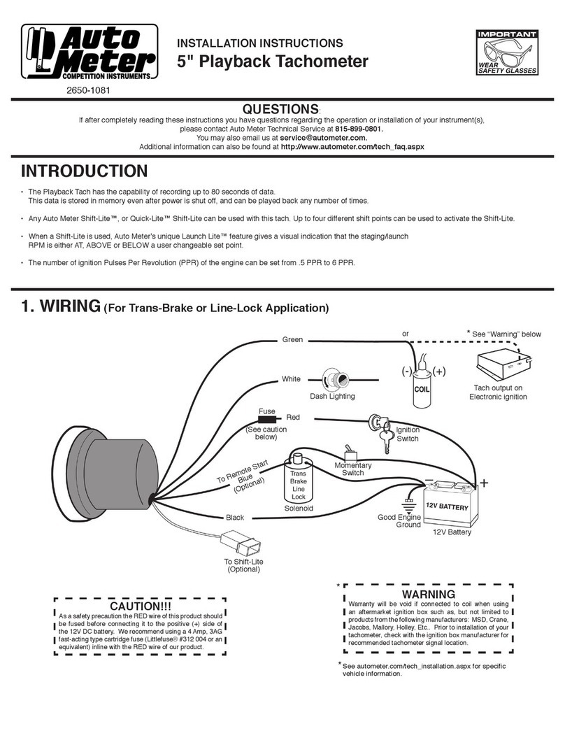
AutoMeter 2650-1081 User manual

AutoMeter

AutoMeter 2650-1081 User manual

AutoMeter SB-52 User manual

AutoMeter

AutoMeter SB-52 User manual

AutoMeter BVA-200EX User manual

AutoMeter

AutoMeter BVA-200EX User manual

AutoMeter BVA-230OZR User manual

AutoMeter

AutoMeter BVA-230OZR User manual

AutoMeter 6858 User manual

AutoMeter

AutoMeter 6858 User manual

AutoMeter Spek Pro Installation manual

AutoMeter

AutoMeter Spek Pro Installation manual

AutoMeter 5798 User manual

AutoMeter

AutoMeter 5798 User manual

AutoMeter BCT-460 Use and maintenance manual

AutoMeter

AutoMeter BCT-460 Use and maintenance manual

AutoMeter RC-300 User manual

AutoMeter

AutoMeter RC-300 User manual

AutoMeter BVA-350 User manual

AutoMeter

AutoMeter BVA-350 User manual

AutoMeter 5336 User manual

AutoMeter

AutoMeter 5336 User manual

Popular Measuring Instrument manuals by other brands

AEMC 565 user manual

AEMC

AEMC 565 user manual

Mic 98651 Operation manual

Mic

Mic 98651 Operation manual

Rigol DL3032 user guide

Rigol

Rigol DL3032 user guide

sisel ENDA EI741A quick start guide

sisel

sisel ENDA EI741A quick start guide

WoMaster ES100 Series Quick installation guide

WoMaster

WoMaster ES100 Series Quick installation guide

Circutor Getest instruction manual

Circutor

Circutor Getest instruction manual

Klein Tools ET50 instruction manual

Klein Tools

Klein Tools ET50 instruction manual

WeatherMate WM300 manual

WeatherMate

WeatherMate WM300 manual

Sonel PQM-702 quick guide

Sonel

Sonel PQM-702 quick guide

PCE Instruments PCE-TG 75 user manual

PCE Instruments

PCE Instruments PCE-TG 75 user manual

Kobold KSV operating instructions

Kobold

Kobold KSV operating instructions

MFJ 223 instruction manual

MFJ

MFJ 223 instruction manual

Sharp HR-GB201 quick start guide

Sharp

Sharp HR-GB201 quick start guide

Oakton pH 5+ instruction manual

Oakton

Oakton pH 5+ instruction manual

IFM Electronic efector 200 OJ50 Series operating instructions

IFM Electronic

IFM Electronic efector 200 OJ50 Series operating instructions

AccuEnergy AcuRev 1200 Series user manual

AccuEnergy

AccuEnergy AcuRev 1200 Series user manual

Emos P5805 manual

Emos

Emos P5805 manual

PAT DS 150 Service manual

PAT

PAT DS 150 Service manual

manuals.online logo
manuals.online logoBrands
  • About & Mission
  • Contact us
  • Privacy Policy
  • Terms and Conditions

Copyright 2025 Manuals.Online. All Rights Reserved.