Cine Gears Ghost-Eye 800TC Product guide

800TC WIRELESS HDMI/SDI
VIDEO TRANSMISSION SYSTEM
MANUAL BOOK
GHOST EYE
© 2017 Cine Gears INC. All Rights Reserved.

Trademarks
Ghost-Eye Wireless Video Transmission SystemsTM are trademarks of Cine Gears
Inc. Web Interface.
Statement of Conditions
In the interest of improving internal design, operational function, and/or reliability, Cine
Gears Inc. reserves the right to make changes to the products described in this docu-
ment without notice.
Cine Gears Inc. does not assume any liability that may occur due to the use or applica-
tion of the product(s) or circuit layout(s) described herein.
FCC Compliance Notice: Radio Frequency Notice
The device has met the FCC 15.247 requirement. In order to comply with the FCC RF
exposure requirement, the user must keep 20cm away from the antenna.
This device has been tested and found to comply with the limits for a Class B digital
device, pursuant to part 15 of the FCC Rules. These limits are designed to provide
reasonable protection against harmful interference in a residential installation. This
device generates, uses, and can radiate radio frequency energy and, if not installed
and used in accordance with the instructions, may cause harmful interference to radio
communications. However, there is no guarantee that interference will not occur in a
particular installation. If this device does cause harmful interference to radio or televi-
sion reception, which can be determined by turning the equipment off and on, the user
is encouraged to try to correct the interference by one or more of the following mea-
sures:
• Reorient or relocate the receiving antenna.
• Increase the separation between the equipment and receiver.
• Connect the equipment into an outlet on a circuit different from that to which the
receiver is connected.
• Consult the dealer or an experienced radio/TV technician for help.
© 2017 Cine Gears INC. All Rights Reserved.

Information to the user
The user’s manual or instruction manual for an intentional or unintentional radiator
shall caution the user that changes or modifications not expressly approved by the
party responsible for compliance could void the user’s authority to operate the equip-
ment. In cases where the manual is provided only in a form other than paper, such as
on a computer disk or over the Internet, the information required by this section may
be included in the manual in that alternative form, provided the user can reasonably be
expected to have the capability to access information in that form.
© 2017 Cine Gears INC. All Rights Reserved.
Contents
Cautions
Ghost Eye Wireless Video Transmission Systems
Product Features
Specifications
Transmitter
Receiver
User Manual
Setting Up the Unit
Setting Up the Intercom
Setting Transmission Output Power
Channel Settings
Turning Fan On/Off
Troubleshooting
Disclaimers
About Cinegears
1
2
3
4
5
7
9
11
17
11
13
14
13
15
14
19
© 2017 Cine Gears INC. All Rights Reserved.

Cautions
© 2017 Cine Gears INC. All Rights Reserved. 2
Please read this user introduction manual to become familiar with the features of the Ghost-Eye series
products before operation. Failure to operate the product correctly can result in damage to the product,
or interference with other devices. This is a sophisticated product which must be operated with caution and
common sense. Failure to operate this product properly might result in disturbing other film equipment on set.
This product is not intended for use bychildren without direct adult supervision. Do not use with incompatible
components, or alter this product in any way outside of the documents provided by Ghost-Eye. These safety
guidelines contain instructions for installation, operation, and maintenance. It is essential to read and follow
all of the instruction in the manual, and all the notices and warnings regarding Ghost-Eye series products
prior to assembly, setup, or use to prevent any damage or interference.
1. Do not use this product in extreme heat, cold, dusty, or humid environments.
2. Prevent friction against hard objects.
3. Prevent jarring, such as from falling from high places, or from improper packaging during transportation.
4. These products are not waterproof; prevent moisture from getting in, on, or around the unit(s).
5. Do not dismantle, assemble, or otherwise alter the product(s) arbitrarily.
1. When this device is sharing a power supply or battery with other equipment, please make sure all signal
and power cables are well connected before turning on the Ghost-Eye unit power.
2. When this device is sharing a power supply or battery with other equipment, please make cables from the
Ghost-Eye unit.
3. When this device is sharing a power supply or battery with other equipment, please check the polarity of
the power connectors of all equipment to ensure the inside conductor is positive. If the polarity of the power
connector is unknown, please check the user manual to make sure the outer conductor of the SDI or HDMI
connector is connected to the negative of the power supply. Otherwise, the equipment will not be able to
share the same power supply withthe Ghost-Eye unit.
Warning
Electrical Considerations

Ghost Eye Wireless Video Transmission Systems
© 2017 Cine Gears INC. All Rights Reserved. 3
Here at Cine Gears Inc., we supply some of the best wireless HD video transmitters and receivers available.
During the development of Ghost-Eye units, we subjected our prototypes to rigorous testing on set with
professional film crews, and took customer feedback and suggestions into serious consideration. After careful
consideration, Ghost-Eye products have integrated all the in-demand wireless video transmission features
recommended by you, the user. The fruit of our efforts are catalogued below in the form of our unique
Ghost-Eye Wireless Video Transmission kits, across the affordable price range spectrum.
Ghost Eye wireless video transmission kits each fit a different set of wireless HD video transmission needs.
The most powerful video transmitters and receivers will satisfy even the most high end profesional film crew,
and our lightweight models fit a more versatile brand of film set. Ghost-Eye transmission kits transmit and
receive 10 bit, 4:4:4 video, support both HD and SD, and can broadcast with less than 1ms/1 frame latency.
The transmitter’s output power can be adjusted between 10dBm to 21dBm to suit your shooting environment.
At 100% power, the transmission range is at it’s maximum of 800-1000 meters (2624-3280 feet). At 50%
power, the transmission range is up to 200-300 meters (656-984 feet). The 2.4G tally and talk-back range
reaches up to 600 meters (1968 feet).

Product Features
© 2017 Cine Gears INC. All Rights Reserved. 4
Transmits 10-bit color, YCbCr, 4:2:2 color depth, proprietary color matching algorithm on OFDM
chips.
Optimized uncompressed 10-bit 4:2:2 2GBps video stream, or 12-bit 4:4:4 3GBPs wireless video
transmission on other models.
Optimized video processor for on-screen movement.
Fully supports all audio formats.
Static channel selection. The channel number and frequency can be modified by software to avoid
interference from other devices. Supports multiple receivers and AES 128 bit video encryption.
FPGA technology adopting American IRTA programmable logic matrix chips.
Follows the international film association time code protocols. Accurate time code extraction,
transmission, and encryption using embedded time code transmission method. Hardware
encrypted time code to IRTA chips.
Software allows user to adjust transmission output power to avoid interference.
Uses a separate channel to transmit tally information. Fully supports different intercom interfaces.
Integrated wireless intercom feature supports up to 300 meters for microphone and speakers.
Supports external bluetooth audio devices. Wireless microphones can be adapted.
Certified software and technical support provided. For organizations, customized frequency, power
and products available for organizations.
Specifications
© 2017 Cine Gears INC. All Rights Reserved. 5
ITEM SPECIFICATION
Frequency range
5.1-5.9(GHz)*Subject to different RF
regulations in different regions.
2.4-2.483GHz with ISM band
Modulation method and
Bandwidth
OFDM/40MHz for video
GFSK/1MHz for intercom system
Video Formats
Supported
1080p 23.98/24/25/30/50/60
1080i 50/59.94/60
720p 50/59.94/60
576p 576i 480p 480i
Audio Formats
Supported PCM, DTS-HD, Dolby TrueHD
Time Code SMPTE-12M
Transmission Range 3280ft(Line of sight)
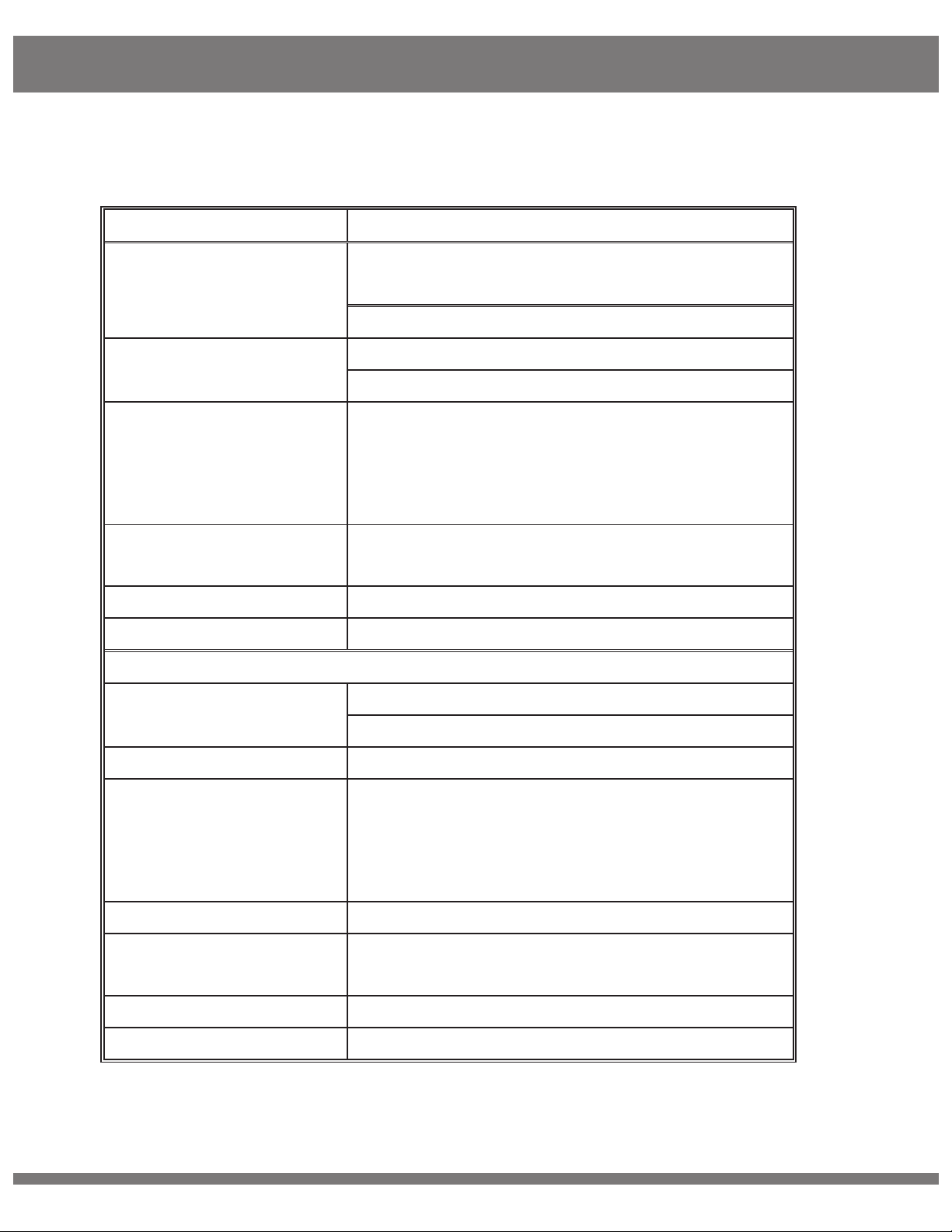
Transmitter
Antenna External Antenna 5G × 2pcs
External Antenna 2.4G x1pcs
Transmission Power 18dBm
Functional Interface
HDMI Input; SDI Input; SDI Loop Output; Mini
USB; LEMO Power IN; Antenna RPSMA
Socket; Power ON/OFF,3.5mm HP/MIC socket
TALLY output for Wrist
Mounting Structure 1/4” Hot-shoe connection
OLED Display Channel Info; Video status; Battery capacity;
Status Menu, Audio Volume
Power Source 9-18V for DC input, F550/F970 battery
Power Consumption 7.5-8.5W
Specifications
© 2017 Cine Gears INC. All Rights Reserved. 6
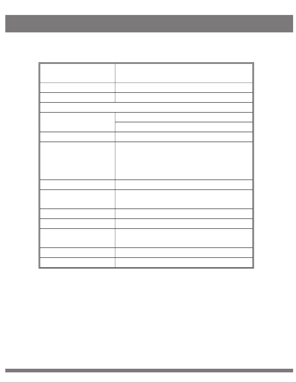
Net Weight(with
antenna)
400g
Dimensions 142.5×76×24.3mm
Temperature -10-50º (Operating); -40-80º (Storage)
Receiver
Antenna External Antenna 5G × 5pcs
External Antenna 2G x1pcs
Receiving Sensitivity -70dBm
Functional Interface
SDI Dual Output; HDMI Output; Mini USB;
LEMO Power IN; Antenna RPSMA Socket;
Power ON/OFF, 3.5mm HP/MIC socket;3.5mm
TALLY socket; LEMO 6 needle
Locating Structure
1/4” Hot-shoe connection
OLED Display Channel Info; Signal Strength; Power Info;
TALLY indicator
Power Source 9-18V for DC input; SONY V-mount battery
Power Consumption 7.5-8.5W
Net Weight(with
antenna) 800g
Dimensions 169.5×122×25.2mm
Temperature
-10-50º (Operating); -40-80º (Storage)
*Since the product’s improving process, all the performance, design and specifications
of our products are subject to minor change without prior notice.
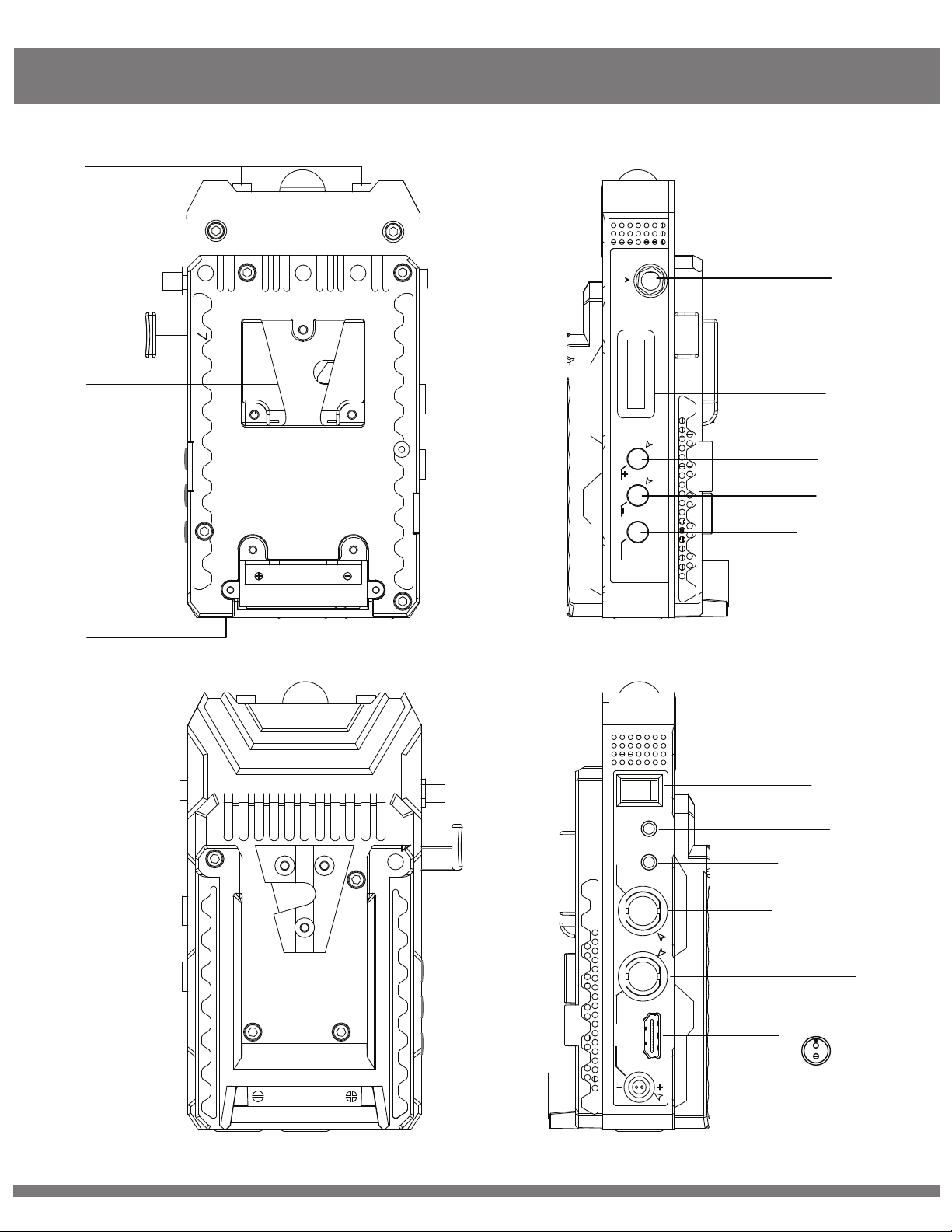
Transmitter
© 2017 Cine Gears INC. All Rights Reserved. 7
MENU
T
Front TALLY
2.4G Antenna
LCD Display
MENU
VOL +/sel
VOL -/sel
Rear TALLY
Battery Clip
5G Antenna 1
14
15
16
2
3
4
5
6
ON
OFF
TALLY MIC/HP
SDI IN SDI
OUT
HDMI IN
DC IN
9V-18V
Power
ON/OFF
EXT TALLY output
MIC/HP
SDI IN
SDI OUT(Loop Through)
HDMI IN
Power Supply IN(Lemo)
+
9V-18V
7
8
9
10
11
12
13

Transmitter
© 2017 Cine Gears INC. All Rights Reserved. 8
STRUCTURE
15mm Front TALLY indicator (Red/Yellow)
1
2
3
4
5
6
7
8
9
10
11
12
13
14
15
16
The indicator color will be the same (Red/Yellow) for rear, front, and external TALLY.
2G Antenna Connector
SMA connector for 2.4G antenna.
OLED Display
Displays information for channel, video status, signal strength, battery voltage indicator, and MENU information.
VOL + / UP Button
Volume + function. In MENU mode, the button functions as an UP key.
VOL - / DOWN Button
Volume - function. In MENU mode, the button functions as a DOWN key.
MENU Button
Power ON/OFF
Power ON or OFF the transmitter.
3.5mm External TALLY Output Interface
Maximum output current of 20mA, can support LED.
3.5mm MIC/HP Interface
Connect to external converter box.
SDI IN
Connect to video source. Supports 3G-SDI, HD-SDI, SD-SDI.
SDI OUT (Loop Through)
Connect to other SDI equipment if needed.
HDMI IN
Connect to HDMI video source.
DC Power In (Lemo)
Supports 9-18V.
5G Antenna Connectors
RPSMA connectors for 5G antennas.
Battery Clip
Battery compartment, for F550/F970 batteries.
Rear TALLY (Red/Yellow)
The indicator color will be the same (Red/Yellow) for rear, front, and external TALLY.
MENU select. In MENU mode, the button functions as a confirm key.
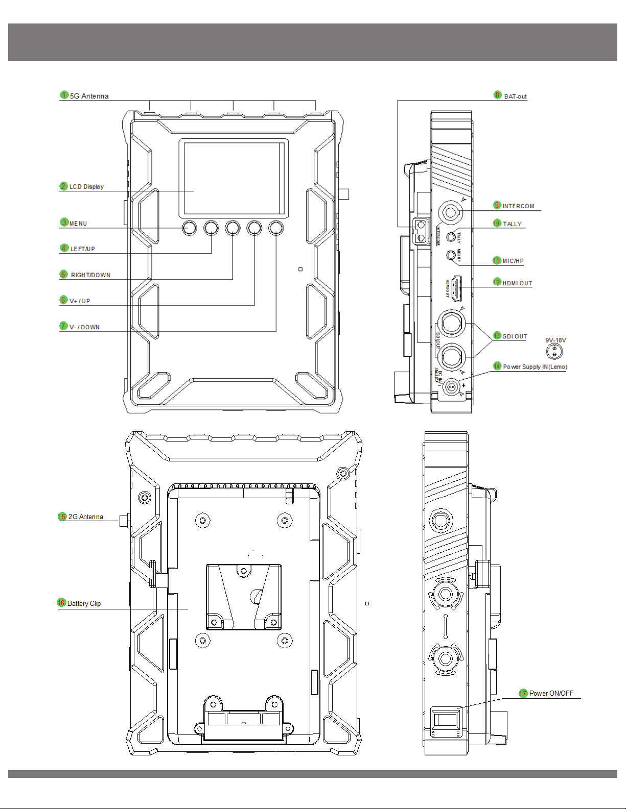
Receiver
© 2017 Cine Gears INC. All Rights Reserved. 9
© 2017 Cine Gears INC. All Rights Reserved. 10
Receiver
STRUCTURE
5G Antenna Connectors
1
2
3
4
5
6
7
8
9
10
11
12
13
14
15
16
17
RPSMA connectors for antennas.
OLED Display
Channel, signal strength, battery voltage, audio volume, and MENU.
MENU Button
Unlock and confirm selection.
LEFT / UP Button
Select channels.
RIGHT / DOWN Button
Select channels.
V+ / UP Button
V- / DOWN Button
Volume -.
BAT-OUT
Provides DC power from the battery for an external device.
INTERCOM
6pin LEMO for TALLY and intercom system.
3.5mm External TALLY Output Interface
Maximum output of 20mA, can support LED.
3.5mm MIC/HP Interface
Connect to external headphone.
HDMI OUT
Video output, connect to HDMI receiver or device.
SDI OUT
Video output (video output is the same from the two SDI interfaces), connect to SDI receiver or device.
DC Power In (LEMO)
Supports 9-18V.
2.4G Antenna Connector
SMA connector for 2.4G antenna.
Battery Clip
V-Mount battery (default) battery plate.
Power ON/OFF
Power ON or OFF the receiver.
Volume +.

User Manual
© 2017 Cine Gears INC. All Rights Reserved. 11
1.
Fix the three antennas to the transmitter and arrange them to be a right angle as below figure
to get better performance.
2.
On transmitter side, when both SDI and HDMI source are inputted, the transmitter will
automatically select the SDI source for transmission
3.
Fix the five antennas to receiver and arrange them to a right angle as figure to get better
performance.
4. Setting the receiver higher will enhance the transmission distance.

User Manual
© 2017 Cine Gears INC. All Rights Reserved. 12
Transmitter
Fix the three antennas (5G x2, 2.4G x1) respectively.
Connect the SDI or HDMI video source to the “SDI IN”/”HDMI IN” of transmitter (when both SDI and
HDMI video are inputted, it will auto select the SDI video for transmission).
If needed, you can connect the SDI out (loop through) to other equipment as well.
Connect the DC power to the transmitter or use a battery on the battery plate.
Power on the transmitter.
Set the Channel (must set both transmitter and receiver to the same channel)
Receiver
Fix the six antennas (5Gx5, 2.4Gx1) respectively.
Connect the “SDI OUT”/”HDMI OUT” port of the receiver to the monitor or other device.
Connect DC power via power cable or use V-lock battery on the battery plate.
Power on the receiver.
Set the Channel (must set both transmitter and receiver to the same channel).
After 5-10s, the video transmission will be shown on the monitor.

User Manual
© 2017 Cine Gears INC. All Rights Reserved. 13
Setting Up the Intercom
Changing Transmission Output Power
Press the “+” and “-” buttons on the transmitter simultaneously for 3 seconds.
Press “+” or “-” to select “PWR.” Press MENU to confirm.
Press “+” or “-” to increase or decrease transmission output power.
Press MENU to confirm.
After connecting the units, power on both Transmitter and Receiver.
On the Transmitter side, you will hear sound from the receiver end if “TALK” is not
pressed on converter box.
When the “TALK” button is pressed and held, both the receiver end and the transmitter end
can conversation normally.
The receiver end can hear “call sound” when the operators on the Transmitter side
press down the “CALL” button on CALL box.
When TALLY is triggered via a professional broadcast switcher, the OLED area on the receiver
glow red. At the same time, the “TALLY” LED will be lit on the Transmitter (You can also insert
your wrist indicator if desired).
Note: The external TALLY ( wrist LED) interface only supports LED lights at 3.3V@20mA.
Intercom System Pairing
Transmitter (TX) side: Press “MENU” button first, then press “UP” or “DOWN” buttons to choose
“Talk Pair” on screen and press “MENU” button again to confirm.
Receiver (RX) side: Press “VOL-” button first, then press “RIGHT” button to start intercom pairing.
Transmitter (TX) side will auto restart, Receiver(RX) side should be manually restarted.
When both sides are restarted, Intercom system pairing is complete.

User Manual
© 2017 Cine Gears INC. All Rights Reserved. 14
Channel Settings
Both Transmitter and Receiver are set to the same channel by default. If you want to change to a new
channel, please follow the instructions below.
Note: Both transmitter and receiver must be set to the same channel to work.
Changing Channel on Transmitter
Power on the Transmitter
Press the “MENU” button, then press “UP” or “DOWN” to choose “Channel Set”
on screen. Press “MENU” to confirm.
Press “UP” or “DOWN” to choose channel, then press “MENU” to confirm.
Transmitter channel setting accomplished.
Changing the Channel on Receiver
Power on the Receiver.
Press and hold “MENU” button until display unlock icon appears
Click “LEFT” or “RIGHT” buttons to choose channel, then click “MENU” to confirm.
Receiver channel setting accomplished.
Turning the Fan On or Off
Press the “+” and “-” buttons on the transmitter simultaneously for 3 seconds.
Press “+” or “-” to select “FAN.” Press MENU to confirm.
Press “+” or “-” to turn fan ON or OFF.
Press MENU to confirm.
User Manual
© 2017 Cine Gears INC. All Rights Reserved. 15
Troubleshooting
If the Receiver fails to output video correctly, follow the chart below to find possible causes and solutions.
Transmitter is not powered up. Turn on the transmitter.
Transmitter or receiver is not placed
correctly.
The transmitter and receiver are too
far away.
Several solid wall partition on TX and
RX.
There are too many obstacles between
TX and RX.
Other transmitter is working on the
same or adjacent channel
ISSUE
OSD Information on TV
SOLUTION
Transmitter and video source are not
connected.
The video source is turned OFF
Displaying “Waiting for Connection...” for a Prolonged Period
No Video Signal Received
Bad connection of transmitter cable
Transmitter is working abnormally
Problem with the cable between TX
and video source
Player does not support the output
resolution format
The TV/Monitor does not support
HDCP authentication
Place the TX or RX correctly.
Move the receiver closer to the
transmitter.
Reduce the number of obstructions
between the TX and RX.
Move the receiver closer to the
transmitter.
Turn off other transmitter, or
change channel.
Connect the transmitter to video source
by SDI/HDMI cable.
Turn on the video source.
Disconnect and re-connect the transmitter.
Restart the transmitter.
Change the SDI/HDMI cable.
Switch the output video resolution to
other modes.
Replace TV/Monitor with HDCP-Certified
TV/Monitor.
User Manual
© 2017 Cine Gears INC. All Rights Reserved. 16
Receiver is turned off. Turn on the receiver.
Receiver and TV are not connected.
TV/Monitor not switched to SDI/HDMI
input
Bad cable connection of receiver or
TV/Monitor.
TV/Monitor turned to standby mode.
Receiver is working abnormally.
Image
Bad connection from receiver or
cable.
Receiver is working abnormally.
No Signal Input to Receiver or TV/Monitor
No Image Appears on the TV/Monitor
Abnormal Color on TV Screen
Receiver failure.
Bad connection from receiver cable
or TV/Monitor.
Bad connection from transmitter cable
or video source.
Transmitter or receiver working
abnormally.
Connect receiver and TV/Monitor
via SDI/HDMI input.
Switch TV/Monitor to SDI/HDMI input.
Disconnect and re-connect the SDI/HDMI
cable.
Switch the TV/Monitor to normal
operation mode.
Restart the receiver.
Reconnect the cable of the receiver or
TV/Monitor.
Restart the receiver.
Please contact your retailer.
Disconnect and re-connect the HDMI
cable of the receiver or TV.
Disconnect and re-connect the HDMI
cable of the transmitter and player.
Restart transmitter and receiver.

Disclaimers
© 2017 Cine Gears INC. All Rights Reserved. 17
This equipment has been tested and found to comply with the limits for a Class B digital device,
pursuant to part 15 of the FCC rules. These limits are designed to provide reasonable protection against
harmful interference in a residential installation. This equipment generates, uses and can radiate radio
frequency energy and, if not installed and used in accordance with the instructions, may cause harmful
interference to radio communications. However, there is no guarantee that interference will not occur in
a particular installation. If this equipment does cause harmful interference to radio or television reception,
which can be determined by turning the equipment off and on, the user is encouraged to try to correct
the interference by one or more of the following measures:
-Reorient or relocate the receiving antenna.
Increase the separation between the equipment and receiver.
Connect the equipment into an outlet on a circuit different from that to which the receiver is connected.
Consult the dealer or an experienced radio/TV technician for help.
To assure continued compliance, any changes or modifications not expressly approved by the party
responsible for compliance could void the user’s authority to operate this equipment. (Example use only
shielded interface cables when connecting to computer or peripheral devices).
This equipment complies with FCC RF radiation exposure limits set forth for an uncontrolled environment.
This transmitter must not be co-located or operating in conjunction with any other antenna or transmitter.
This equipment complies with part 15 of the FCC Rules.
Operation is subject to the following two conditions:
(1) This device may not cause harmful interference.
(2) This device must accept any interference received, including interference that may cause undesired
operation.
The manufacturer is not responsible for any radio or TV interference caused by unauthorized
modifications to this equipment. Such modifications could void the user authority to operate the
equipment.
FCC Statement
FCC Radiation Exposure Statement
Cautions
Table of contents
Other Cine Gears Transmitter manuals


Popular Transmitter manuals by other brands


HumanTechnik
HumanTechnik lisa operating instructions

Xylem
Xylem MJK pHix Compact manual

AUDIOropa
AUDIOropa pro:ton SP-100M user manual

Celluon
Celluon magic cube user guide

AMX
AMX Advanced Classroom Transmitter TXC-ACT instruction manual

Distech Controls
Distech Controls HS-O 2X Series Hardware installation guide