Cinemateq Picture optimizer User manual

picture optimizer plus HD (SDI)
Video picture optimizer
User Manual
English
As of firmware version 1.20

Table of contents
Important notes ......................................................................................................................................................... 61
Introduction................................................................................................................................................................ 62
Support Hotline......................................................................................................................................................... 62
Installation in 6 steps................................................................................................................................................. 63
Step 1: Check scope of delivery ................................................................................................................................. 63
Step 2: Setup & connection ....................................................................................................................................... 63
Step 3: Connection of other devices .......................................................................................................................... 66
Step 4: First operational steps.................................................................................................................................... 69
Step 5: Operation elements & remote control ............................................................................................................ 69
Step 6: Basic configuration ........................................................................................................................................ 71
Operation ................................................................................................................................................................... 75
General functions...................................................................................................................................................... 75
Video switcher .......................................................................................................................................................... 75
TV-Mode................................................................................................................................................................... 77
Overscan................................................................................................................................................................... 77
Configuration - the main menu ................................................................................................................................ 79
Input setup................................................................................................................................................................ 79
Assignment of audio sources
Output setup............................................................................................................................................................. 84
Filter setup ................................................................................................................................................................ 85
Expert menu.............................................................................................................................................................. 86
Custom resolution for PAL / NTSC ............................................................................................................................. 86
Other options............................................................................................................................................................ 87
The optimum configuration ...................................................................................................................................... 89
Connection of video sources & displaying device(s) .................................................................................................... 89
Connection of a flat screen CT-50 (control box)......................................................................................................... 90
Resolution & frame rate............................................................................................................................................. 91
Picture parameters & filters........................................................................................................................................ 92
RS-232 control ............................................................................................................................................................ 93
Operation via RS-232 ................................................................................................................................................ 93
RS-232 control for other devices................................................................................................................................ 94
Firmware upgrade ..................................................................................................................................................... 95
Tips for error correction ............................................................................................................................................ 97
Addendum................................................................................................................................................................ 100
Connection with analogue displaying devices ......................................................................................................... 100
Resolution and frame rate ...................................................................................................................................... 101
Audio delay............................................................................................................................................................. 105
Connection to a PC ................................................................................................................................................ 105
Maintenance & care ................................................................................................................................................ 106
Warranty................................................................................................................................................................. 106
Technical data ......................................................................................................................................................... 109
61
IMPORTANT NOTES
Please read this user manual in detail in any case BEFORE connecting and taking the picture optimizer plus
HD (SDI) into operation and consider all included set up and security notes. Please keep this user manual in
case you need to refer to it later on.
NEVER connect to and / or disconnect any other device from the picture optimizer plus HD (SDI) via the in- &
outputs, before having switched off the picture optimizer plus HD (SDI) and all other devices and also having
disconnected those from the main power supply. Otherwise irreparable damages in any case excluded from
warranty can happen to the picture optimizer plus HD (SDI) or other devices.
Always take care that all connections to the in- & outputs of the picture optimizer plus HD (SDI) are safely
fixed and if possible screwed (VGA & HDMI/DVI sockets) or protected (BNC sockets). Especially HDMI and DVI
connections are extremely sensitive! “Wobbly“ connections can lead to irreparable damages on the picture
optimizer plus HD (SDI) or other devices which are in any case excluded from warranty.
Only use the external power adapter included in the scope of supply. Damages caused by third party power
supplies are excluded from warranty. Before connecting the external power adapter to the main power supply
it needs to be connected to the picture optimizer plus HD (SDI). Never disconnect power adapter and picture
optimizer plus HD (SDI) if the power adapter is connected to the main power supply.
Changing the preset values for resolution and frame rate can lead to damages at the connected displaying
device in rare cases. Please in any case take into account the maximum values, which can be processed by
your displaying device and in exceed those in neither case when adjusting the settings in the picture optimizer
plus HD (SDI) menu. Any liability from our side for damages caused by such a behavior is excluded.
Only qualified service technicians are allowed to open the picture optimizer plus HD (SDI) or the power
adapter included in the scope of delivery and perform service for the devices. Damages caused by disregard
are in any case excluded from warranty.
Warranty registration
In order to activate the two-year device warranty, you need to register your picture optimizer plus HD (SDI) at
cinemateq within 4 weeks from purchase date.
Please therefore use the online registration form on www.cinemateq.com in the support section under device
registration.
Please note:
Only as a registered customer you will have the possibility to download new firmware (software) versions or new
extension options by the internet.
!
!
!
!
!
!

62
INTRODUCTION
Thank you very much
for your decision to use a cinemateq product. Congratulations for having bought a high quality device designed in
Germany and produced in the EU. As a specialist for quality picture and sound optimization of home theater and
presentation systems we warranty constantly high quality and trouble-free operation of our products.
This user manual stepwise explains the installation and configuration of the cinemateq picture optimizer plus HD with /
without SDI option and describes all functions and settings possible in detail. For further information on the product itself,
about configuration and tips & tricks in case of problems appearing please refer to the support section on
www.cinemateq.com.
In case of any technical questions or problems please contact your cinemateq authorized dealer. He supports you with
correct installation and best possible adjustment and / or set up of the device towards your components and
requirements. All of our cinemateq partners are especially trained by us for best integration of the picture optimizer plus
HD (SDI) into new or existing systems.
SUPPORT HOTLINE
Besides our support hotline is available for technical questions and / or problems concerning cinemateq products.
The actual timing when you can reach the support, you will find on our webpage www.cinemateq.com .
You can reach our support team
by phone: +49 / (0)89 / 8630 76 25
by fax: +49 / (0)89 / 8636 95 59
by email:
In the support section of www.cinemateq.com you will find the latest technical news and downloads, useful tips and
frequently asked questions & answers regarding our products for your reference.

63
INSTALLATION IN 6STEPS
STEP 1: CHECK SCOPE OF DELIVERY
First of all please check the contents of the packaging of your cinemateq picture optimizer plus HD (SDI) in order to make
sure everything is included. The contents are:
picture optimizer plus HD (SDI)
remote control
2 batteries for remote control (’AAA’)
external power adapter (230V ~50Hz)
user manual in German and English
If a part is missing or should be damaged, please immediately contact your dealer. Please keep the packaging in case you
ever need to transport the picture optimizer plus HD (SDI).
The picture optimizer plus HD (SDI) is only configured and operated with the supplied infrared remote control. Thus
please first of all put the remote control into operation: Remove the cover of the battery compartment on the back of the
remote control, insert two type ’AAA’ (LR03) batteries and ensure the right polarity (plus-poles point downwards). Close
the battery compartment cover. The remote control is now ready for use.
STEP 2: SETUP &CONNECTION
Setup
The picture optimizer plus HD (SDI) should be positioned next to your video source(s), depending on the length of the
connection cables you have chosen.
nstatus LED (RED = Standby, BLUE = operation) oinfrared receiver for remote control pdisplay
The picture optimizer plus HD (SDI) is only configured and operated by infrared remote control. Please select a location in
which there are no obstructions – such as cabinet doors or any other appliance – in between the infrared receiver (o) and
the remote control.
Please also make sure that you can see the picture of your displaying device whilst operating the picture optimizer plus
HD (SDI) with the remote control as you will not be able to use the device’s on-screen menu. Locations in other rooms or
in closed cabinets are not recommended as they are – next to other things – not suitable for operating the video switcher
function of the picture optimizer plus HD (SDI), despite you are using a RS-232 control system.
64
Security notes for setting up the picture optimizer plus HD (SDI)
Set the picture optimizer plus HD (SDI) onto a stable and flat surface.
Keep the picture optimizer plus HD (SDI) away from radiators and other sources of heat and protect it from
direct sunlight.
If the picture optimizer plus HD (SDI) is set up in a cabinet or similar, leave about 5 cm space around the
device, so that air can circulate unhindered in order to avoid accumulation of heat.
Do not place any objects, little blankets or the like on the device, in order to avoid accumulation of heat.
The picture optimizer plus HD (SDI) should not be exposed to any drops or splashes of water nor any objects
filled with liquids (e.g. vases) should be placed on the device.
Connections
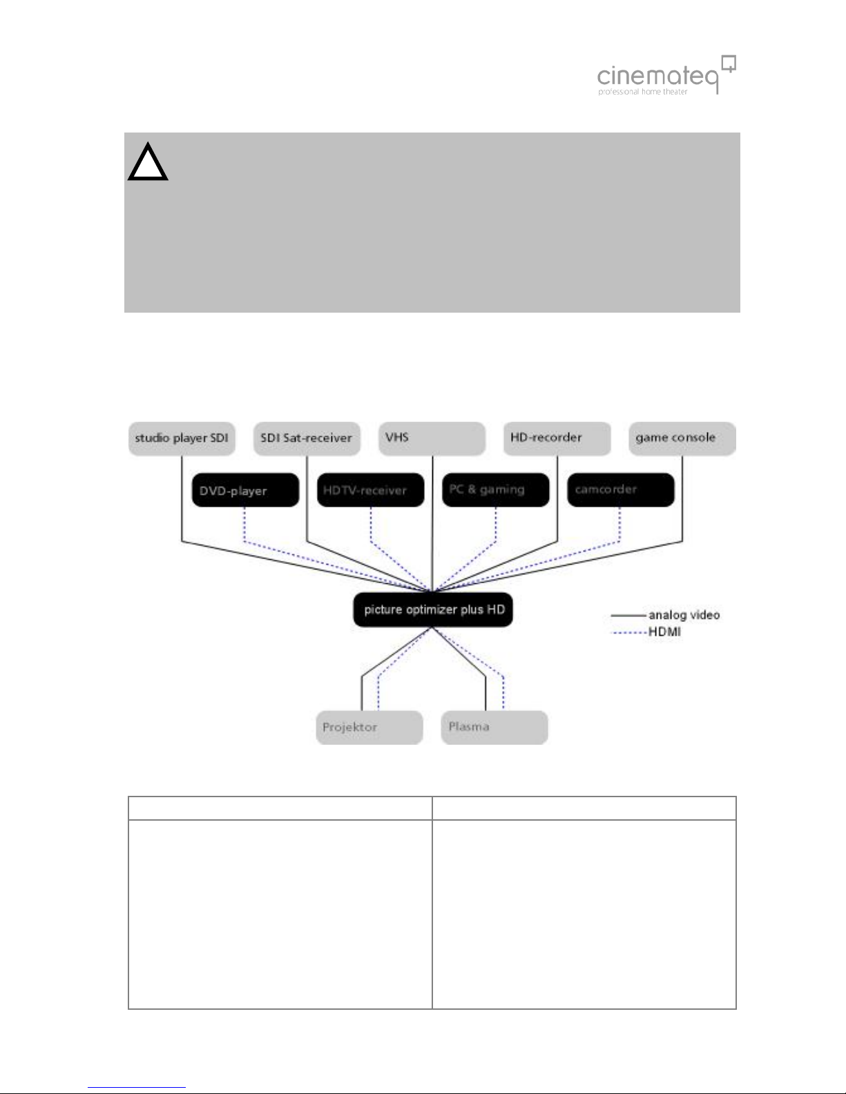
The picture optimizer plus HD (SDI) should be placed between video source(s) and displaying device(s) like in the following
example:
The following devices are suitable for connection to the picture optimizer plus HD (SDI):
Video sources (input) Displaying devices (output)
DVD player, DVD recorder
analog or digital VCR
HDTV -, SAT-, Pay-TV-, cable- or digital receiver
TV-Tuner or personal TV system
video switchers or home cinema receivers with video
switch
game console and media center
Computer and media center
Hard Disc recorder
CRT projector *
digital DLP- or LCD-projector
plasma- or LCD-screen
TV with special “progressive input“*
rear projection TV with progressive and / or VGA input *
(for PC)
analog PC monitor*
TFT monitor
Any “HD ready” device
* (only SDTV)
!

65
The following interfaces and signal variants are offered for connecting the mentioned devices – the order of interfaces
equals the quality of the video signal transferred:
Inputs Outputs
2 x SDI* (BNC socket) for SDI signals (digital)
4 x HDMI (HDMI socket)
for HDMI and (by adapter) DVI signals
2 x YUV** (3 Cinch socket)
for component signals (YUV)
1 x SCART (SCART socket)
for RGB or Composite (FBAS) signals
2 x S-Video (mini DIN connector)
for S-Video signals
2 x Composite (Cinch socket)
for Composite (FBAS) signals
5 digital audio inputs
( 3 x Coax and 2 x Toslink)
1 x HDMI (HDMI socket)
with digital HDMI/DVI output signal
1 x DVI (DVI socket)
with digital DVI output signal
1 x YUV (with Adapter)
alternatively with component (YUV) or RGsB,
outputsignal
1 x RGB (5 BNC socket)
alternatively RGBHV, RGsB, RGBs or YUV output
signal
1 x VGA (VGA socket)
alternatively RGBHV, RGsB, RGBs or YUV output
signal
2 separated audio outputs
(1 x Coax, 1 x Toslink
*) only picture optimizer plus HDSDI (instead of the composite inputs) **) not suitable for progressive
signals!
Please note
Only “interlaced signals” are accepted by the analogue or respectively SDI inputs (meaning all inputs except
HDMI), this means, for example, a DVD player with (non deactivateable) progressive output (YUV) or a computer
(VGA) cannot be connected to these video inputs!
It is not possible to present coded HDMI/HDCP signals via the analogue outputs.
About SDI
The picture optimizer plus HD SDI integrates two digital SDI inputs. SDI -
Serial Digital Interface
- is a 10-bit interface for
transfer of digital video data originally developed by Sony. The SDI standard is also known as SMPTE 259M. SDI up to
now is mainly used in professional video- and studio technology and enables loss-free transfer of video- (but also audio-)
signals over larger distances. Both DVD players and SAT-/cable receivers can be modified for distribution of data in SDI
data streams.
The crucial advantage is, that SDI is the one and only digital standard input signal being enabled to transfer an
unadulterated 1:1 rendition of the digital video signal of DVD or digital TV without any loss in quality even over larger
distances.

66
STEP 3: CONNECTION OF OTHER DEVICES
Preparation of devices to be connected
In order to ensure a perfect video picture optimization the picture optimizer plus HD (SDI) needs the video signal coming
from the video source with certain “attributes” as a prerequisite and the displaying device is meant to render the
optimized output signal of the picture optimizer plus HD (SDI) without “interference“ (e.g. by filters applied).
Therefore you should check and prepare your video source(s) and your displaying device before connecting them to the
picture optimizer plus HD (SDI).
Video source (e.g. DVD player, SAT receiver)
First connect the source directly to the displaying device without the picture optimizer plus HD (SDI) in order to be able to
access the on-screen menu of the video source:
1. The picture optimizer plus HD (SDI) needs an unfiltered and unchanged video signal. Therefore we recommend
to switch off all picture influencing filter functions such as “noise reduction” via the set up menu of your video
source (e.g. DVD player). Please refer to the user manual of your video source to find out which filter- and / or
picture optimizing functions are available.
2. In case your video source has an integrated “aspect ratio conversion“(mostly DVD players), please set the output
format to 16:9 (not 4:3 or „letterbox“) in the set up menu in either case.
3. The picture optimizer plus HD (SDI) can only process progressive signals at the HDMI inputs. At all other inputs,
only „interlaced“ (SDTV, 567i) signals can be processed.
4. In case you want to connect your video source using the SCART input of the picture optimizer plus HD (SDI), you
should set the SCART output of your video source to RGB output in the device’s set up menu (e.g. AV output =
RGB). If your video source doesn’t support RGB output via SCART (e.g. only S-Video or Composite), you should
– if possible – chose another connection (such as YUV or S-Video output). Please only use a Composite signal via
SCART, if there is no other connection available (therefore the SCART input of the picture optimizer plus HD
(SDI) needs to be set to “Composite“, see page 72).
5. The best possible connection between video source and picture optimizer plus HD (SDI) is a digital connection
via SDI as it transfers the digital video signal unchanged (1:1). As an analog connection we recommend either
RGB (via SCART) or YUV (via 3 x Cinch). S-Video or Composite connections deliver a minor quality signal.
Displaying device (e.g. projector, plasma)
Now please configure the displaying device – still without picture optimizer plus HD (SDI):
1. If your displaying device integrates picture influencing filters and optimizing functions, switch those off also in
the device’s set up menu. Eventual “Key Stone Correction“ or “Overscan“ settings should be switched off or set
to neutral for the time being.
2. We also recommend to set all picture parameters (such as brightness, contrast etc.) to neutral for the time being
as the picture optimizer plus HD (SDI) transfers the optimized video signal with different picture values.
3. The picture format conversion should be adjusted to the displaying device’s format (if 16:9 to 16:9 and / or
“normal“, if 4:3 to 4:3 or “full picture“).
4. The optimal connection between the picture optimizer plus HD (SDI) and your displaying device is a digital
connection via HDMI or DVI. In case your device has no digital HDMI or DVI interface, please check which signal
format “YUV“ or “RGB“ (RGB HV, RGBs, RGsB) is accepted by which analog interface (VGA, 3 x Cinch or 5 x
BNC) of your device and choose on of these options. These settings afterwards also need to be “mirrored” in
the picture optimizer plus HD (SDI) setup later on. The best quality connection depends on your displaying
device, under www.cinemateq.com in the support section you can find recommendations of our testers for the
most common displaying devices.

67
Connection
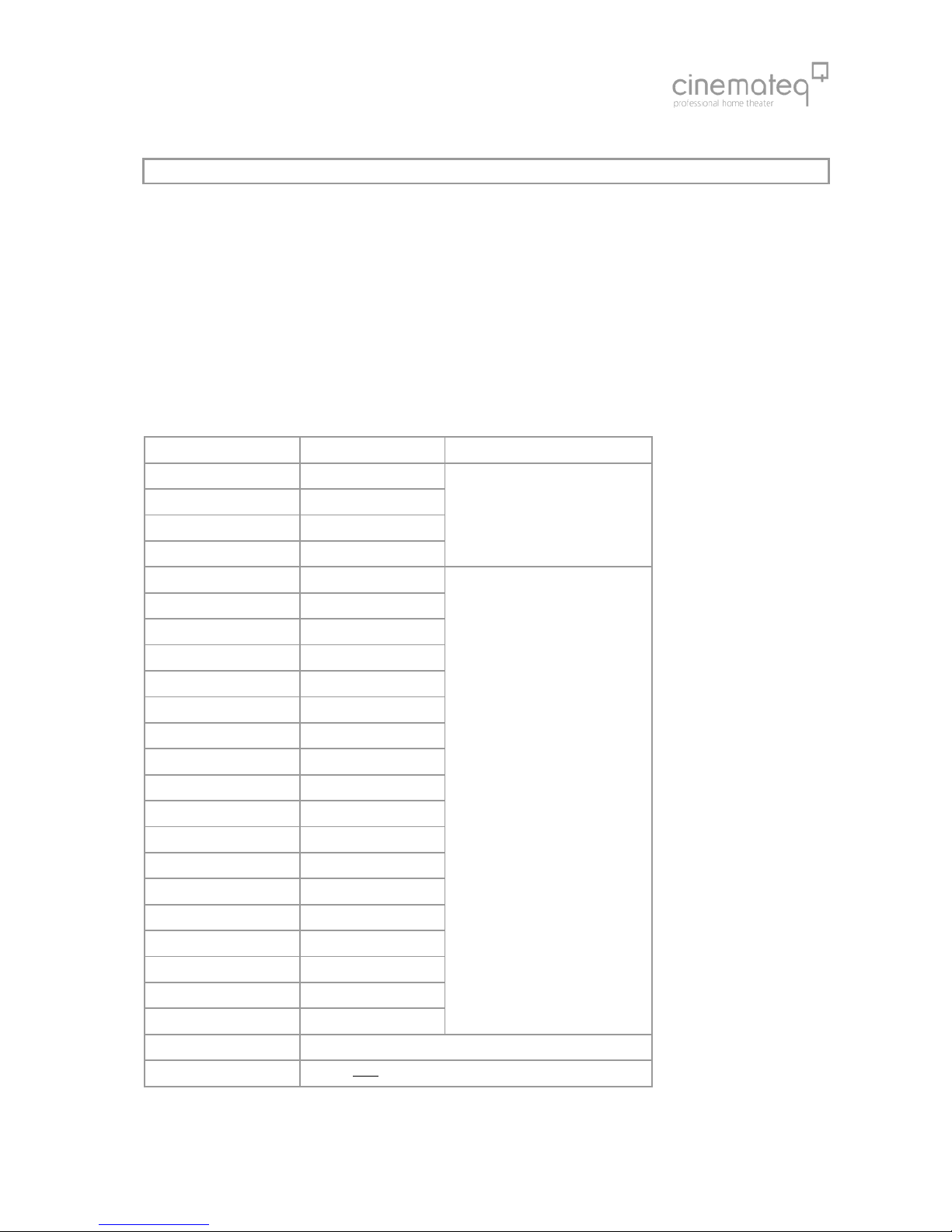
The picture optimizer plus HD offers the following interfaces, at the picture optimizer plus HD SDI the two Composite
inputs (r) are replaced by two SDI inputs (BNC socket):
Category Signal format Remote control
Toslink 1
Toslink 2
1
Toslink 3
Digital Coax
2 Digital Coax
S/PDIF (PCM, DD, DTS)
SDI 1 (Composite 1) [3]
3
SDI 2 (Composite 2)
SDI Serial (576i)
FBAS interlaced [4]
S-Video 1 [5]
4 S-Video 2 Y/C Signal interlaced [6]
YUV 1 [7]
5 YUV 2 Component Signal interlaced [8]
6 Scart RGB or FBAS [2]
HDMI 1 [*] + [1] / [#] + [1]
HDMI 2 [*] + [1] / [#] + [1]
HDMI 3 [*] + [1] / [#] + [1]
7
HDMI 4
Digital HDMI
[*] = processed / [#]= bypass
[*] + [1] / [#] + [1]
8 HDMI Digital HDMI (incl. Audio) / DVI Signal
9 DVI Digital HDMI / DVI Signal
10 RGB H/V RGsB, RGsB3, RGBs, RGBHV, YUV, YUV3
11 VGA RGsB, RGsB3, RGBs, RGBHV, YUV, YUV3
12 Toslink S/PDIF (PCM, DD, DTS)
13 Digital Coax S/PDIF (PCM, DD, DTS)
14 RS232 Serial Interface for firmware upgrade /
operation via RS 232
15 ON / OFF
16 Power 12 V
* several displaying devices cannot process a YUV signal transmitted by a VGA interface, unless a special VGA adapter
cable VGA Adapter Cable (15 Pins on 3 x Cinch) is used, with which H & V Sync is not transmitted.
14 15 16
q
opr
11
12 13
s
tuv
w
pqr
n
68
Security notes for connecting other devices
NEVER connect to and / or disconnect any other device from the picture optimizer plus HD (SDI) via the in- &
outputs, before having switched off the picture optimizer plus HD (SDI) and all other devices and also having
disconnected those from the main power supply. Otherwise irreparable damages - in any case excluded from
warranty - can happen to the picture optimizer plus HD (SDI) or other devices.
Always take care that all connections to the in- & outputs of the picture optimizer plus HD (SDI) are safely
fixed and if possible screwed (VGA-, HDMI - & DVI sockets) or protected (BNC sockets). Especially HDMI and
DVI connections are extremely sensitive! “Wobbly“ connections can lead to irreparable damages on the
picture optimizer plus HD (SDI) or other devices which are in any case excluded from warranty.
TIP:
We recommend to always connect the picture optimizer plus HD (SDI) directly to the displaying device – video
switchers or audio-/video home cinema receivers connected in between can deteriorate picture quality.
We recommend to use high quality cables, as the quality of signal transfer via cable is a crucial factor in video
picture optimizing. Fitting connection cables and adapters for all in- and outputs from cinemateq are available at
your specialized dealer.
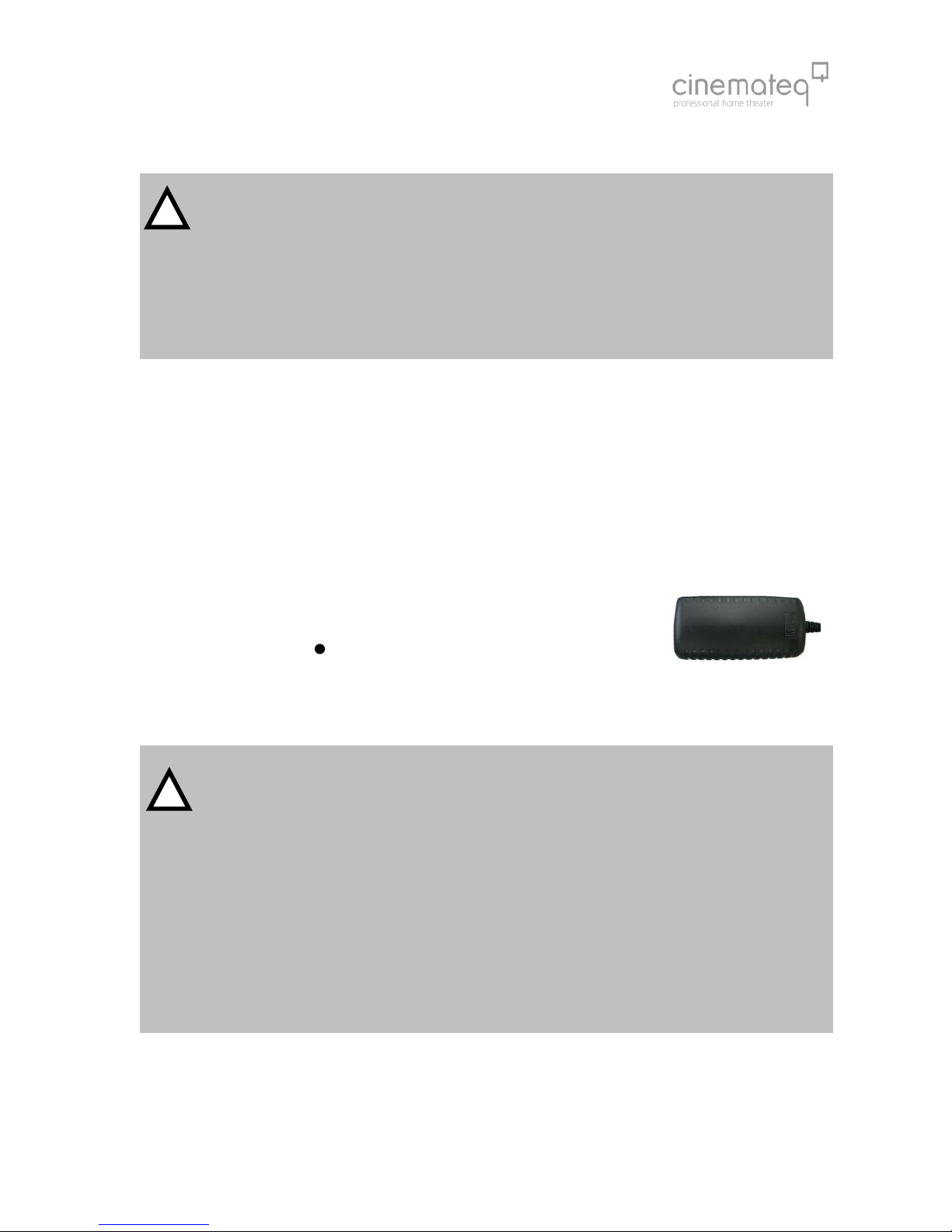
Mains voltage
After having connected the picture optimizer plus HD (SDI) with all video sources and displaying devices, connect the
power adapter. Please take care that
the power adapter must not be connected to the main power supply, when
connecting it to the picture optimizer plus HD (SDI).
the On-/Off switch ( ) of the picture optimizer plus HD (SDI)
is set to “OFF“.
After having connected the power adapter, connect it to the main power supply. Your picture optimizer plus HD (SDI) is
now ready for the first operational steps.
Security notes for connecting the power adapter
Before connecting the external power adapter to the main power supply it needs to be connected to the
picture optimizer plus HD (SDI). Never disconnect power adapter and picture optimizer plus HD (SDI) if the
power adapter is connected to the main power supply.
Only use the external power adapter included in the scope of supply – other power adapters can cause
damages to the device.
Only qualified service technicians are allowed to open the external power adapter and perform service for
the device.
Ensure, that the power adapter never gets in contact with liquids, combustible objects or gases of neither
composition nor is placed next to any of those.
Place the power adapter in a way that ensures a minimum of 5 cm space around the device in order to avoid
accumulation of heat.
If you don’t use the picture optimizer plus HD (SDI) for a longer time please disconnect the power adapter
from the main power supply.
15
!
!
69
STEP 4: FIRST OPERATIONAL STEPS
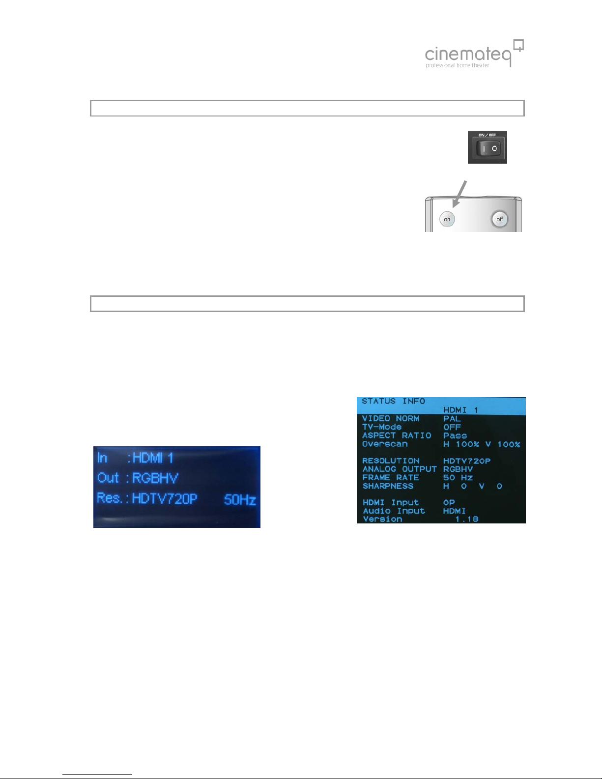
Your picture optimizer plus HD (SDI) is now ready for the first operational steps. To switch the device
on, please set the power switch on the device’s back panel to “ON“ first. The picture optimizer plus
HD (SDI) is now in “stand by mode“, the status LED on the device’s front side shines “RED“, the
display is switched off yet.
Now switch on the connected video source and your displaying device and take care,
that the video source distributes a signal (e.g. DVD player: insert DVD and press “Play“).
Next “wake up” the picture optimizer plus HD (SDI) out of “stand by mode“ using the
“power ON” key on the remote control. The status LED starts flashing RED / BLUE, after
about 5 seconds the display is switched on and shows the basic status info.
Your picture optimizer plus HD (SDI) is now ready for use (= “operating mode“) and can be configured towards your
connected devices.
STEP 5: OPERATION ELEMENTS &REMOTE CONTROL
Operation elements
The operation and configuration of the picture optimizer plus HD (SDI) is performed via the on-screen menu and / or the
graphical info display integrated into the device’s front panel, showing the same content like the on-screen menu in a
compact format.
Info-Display picture optimizer plus HD (Status-Info) On-Screen menu (Status-Info)
On account of simplicity in the following explanations and pictures we nearly exclusively refer to the clearer on-screen
menu, despite it is not visible in the configuration steps.

70
Remote control
power ON
numeric keys
for direct input of values in
dialog boxes
additional:
input selection
direct access to the inputs
via the corresponding
numeric key
navigation arrows
navigation and adjustment
of values in menus and
dialog boxes
[enter] also shows the on-
screen status-info
exit
closes dialogs, saves
changes and/or removes
manu or status overview
option A (*)
with HDMI input in
combination with number
button „scales“ up
tv-mode (tv)
activates and switches of the
„tv-mode“
menu
opens the menu and close it
again
power OFF
(standby)
option B (#)
with HDMI input open
unscaled / suitable for
switching (bypass)
lens shift (S/T)
activates the „electronic lens
shift“ function up [S] or
down [T]
overscan (os)
activates and switches of the
overscan function
aspect ratio (ar)
opens the menu „aspect
ratio“, for the adjustment
auf the aspect ratio.
resolution (res)
opens the menu
„resolution“, for the
adjustment of the output
resolution

71
STEP 6: BASIC CONFIGURATION
In this step you will learn, how the picture optimizer plus HD (SDI) is configured towards the connected devices in order
to reach a correct picture rendition.
An optimal picture rendition using the full spectrum of the picture optimizer plus HD (SDI) needs further adjustments –
please refer to the point “The optimum configuration“ (from page 99 on).
Factory settings
The most important basic settings are shown in the “status info“ in the
display of the picture optimizer plus HD (SDI):
IN: HDMI 1
HDMI 1 is set as active input in factory set up.
Out: RGB HV (analogue) and HDMI & DVI (digital)
The output format is set to RGB HV in factory set up. This signal is
always distributed by all outputs enabled for this.
Res.: 720p ( 50 Hz)
The output resolution is set to “720p“with a frame rate of 50 Hz in PAL (NTSC: 60Hz).
If you have connected your devices according to these factory settings and can already see the picture of the video source
on your displaying device, you can pass by the point “Connection configuration“.
Connection configuration
Before starting, please review the following check list and if necessary enter your values into the table:
(A) Which input of the picture optimizer plus HD (SDI) is the video source you used for basic
configuration connected to (we recommend a DVD player)?
(B) In case it is the SCART 1 input: Which signal format (RGB / Composite) is the video source
distributing via SCART?
(C) In case it is the YUV 1/2 input: Is a possible progressive output of the video source via its YUV
output deactivated?
(D) Which interface (VGA, DVI, 5 x BNC, 3 x Cinch) is your displaying device connected to?
(E) Incase using YUV connections via 3 x Cinch (input or output): Are the cables connected
correctly to the picture optimizer plus HD (SDI) and video source / displaying device?
”Y“ = Green, “U“ (Pb) = Blue, “V“ (Pr) = Red
Connection video source Îpicture optimizer plus HD (SDI)
First, please choose the input your video source is connected to as “active input“ (A).
For this, press the corresponding input button on the remote control (number block), e.g. button [5] for input „S video 1“
or press the „Option A“ button and number „1“ button if the picture source was connected via HDMI 1. The status
indication on the display will change correspondingly to: S video or respectively HDMI 1.
The input for your connected video source is now activated. If you can now see a picture on your displaying device, you
can directly jump to the point “
Resolution & frame rate
“ on page 91.
Notice: The picture optimizer plus HD (SDI) „always“ shows a picture (onscreen display), even if there is no input signal!
72
Conversion of the SCART inputs between RGB ÙComposite
A SCART interface can transmit different signals. The picture optimizer plus HD (SDI) either understands RGB- (highest
quality variant) or Composite signals via its SCART inputs. Factory setting is RGB:
If you would like to switch the SCART input from RGB to Composite, you must change the engagement of this SCART
input in the input menu of the picture optimizer plus HD (SDI) as follows.
(1) Therefore please press the [menu] key on the remote
control once. The “Main Menu“ selection appears in the
display.
(2) Select “Input Setup“ using the [▲] / [▼] keys and
confirm this by pressing the [Enter] key.
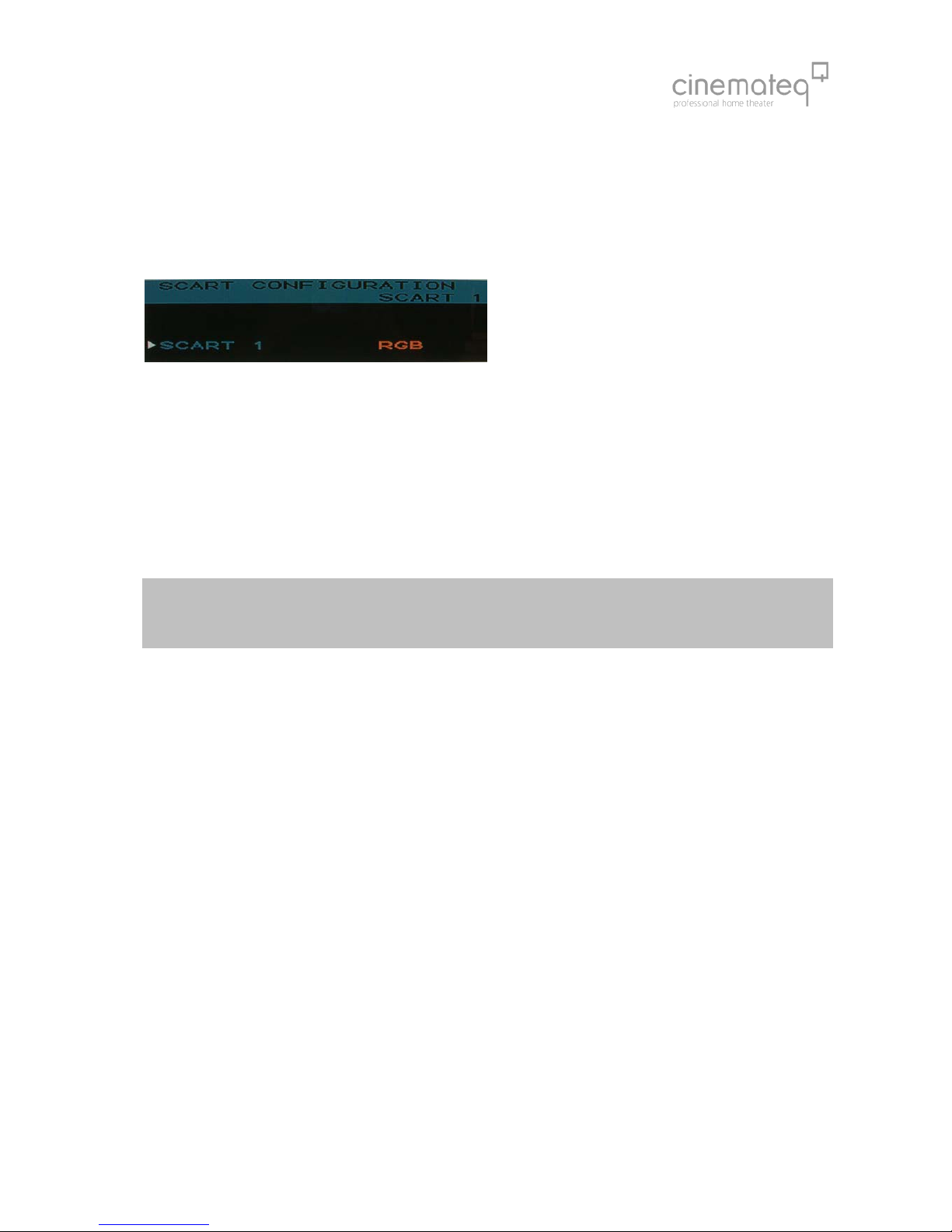
(3) Now select the menu point “ Scart Configuration“ using the arrow keys again and press the [Enter] key.
(4) With the arrow keys now select the menu point “SCART 1“press the [Enter] key.
(5) The currently set value (“RGB“ / “Composite“) is now highlighted in a blue bar, select the desired value with the [+] /
[-] keys and activate it by pressing the [Enter] key.
(6) By pressing the [exit] key you close all menus and get back to the status info.
In the display the status indication changes accordingly after renewed selection of the entrance over the remote
maintenance in: In: SCART 1 Comp.
Please note:
The description of the configuration of analogue outputs can be found in the appendix!
73
ADJUSTMENT OF THE RIGHT RESOLUTION
Crucial for the picture quality of the displaying devices is the addressing with the “right” resolution. This means the
resolution, at which the displaying device can render the video picture without further conversion errors. Best case for
digital devices (such as LCD-/ DLP projectors, plasmas etc.) this is the so called “native“ resolution, i.e. exactly the physical
pixel resolution of the displaying device’s “panel“. Unfortunately the native resolution does not work with all devices as
the control electronics can not process it. Here it applies to find the best possible compromise.
Please first check, which “native resolution“ (also called panel resolution) your displaying device has (e.g. XGA
1024 x 768) – this information can be found in the technical data of the device.
Next select the resolution, that comes nearest to this “native resolution“ in the following table. The picture optimizer plus
HD (SDI) offers 22 different predefined resolutions for both PAL and NTSC signals.
HDMI devices normally resolve the fitting and best picture signal amongst each other. An adjustment of the resolution is
not necessary in this case.
resolutions table
Resolution H x V Norm
Doubling 1440 x 576p / 480p
HDTV 720p 1280 x 720p
HDTV 1080i 1920 x 1080i
HDTV 1080p 1920 x 1080p
SMPTE
PAL
50Hz
for HD ready Panels
Wide-VGA 852 x 480p
480p 1440 x 480p
540p 960 x 540p
576p 720 x 576p
576i / 480i 1440 x 576i/480i
Tripling 1440 x 864p / 720p
Quadrupling 1440 x 1152p / 960p
PDP 1 852 x 1024p
PDP 2 1024 x 1024p
SVGA 800 x 600p
XGA 1024 x 768p
Wide-XGA 1 1280 x 768p
Wide-XGA 2 1365 x 768p
Wide-XGA 3 1366 x 768p
SXGA (4:3) 1280 x 960p
SXGA (5:4) 1280 x 1024p
DILA 1366 x 1024p
UXGA (4:3) 1600 x 1200p
VGA = PC
PAL 50 Hz
NTSC 60 Hz
(Configuration for analogue
outputs see appendix)
custom 1 (480p pre-adjusted)
CT 50 Only for the cinemateq flatscreen CT 50 HD

74
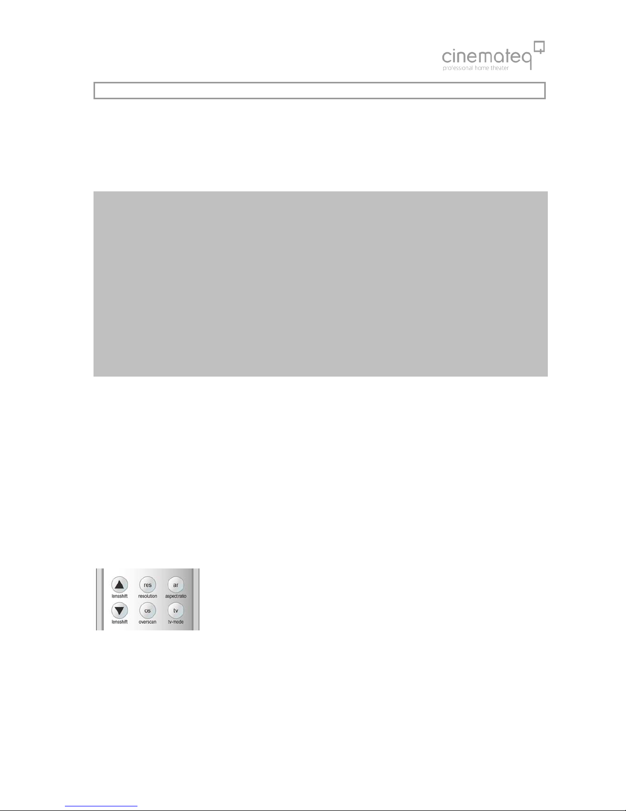
You activate the selected resolution over the remote control:
(1) Please press the key [res].
(2) In the display the menu appears "Active resolution" with the presently
active resolution (e.g. "doubling"). Press now the key [enter], those active
resolution is now deposited blue.
(3) Select now with [+] / [-] keys the desired resolution and activate these with
[enter] key.
(4) By repeated pressing the key [res] the menu "Active resolution" closes.
You can see which resolution is activated on the display (Res) or in the on-screen status info.
In case no picture is shown after having activated the selected resolution, your displaying device does not understand the
selected resolution. Please go back to the initially set resolution (doubling, 720p or 1080i) and test another resolution
coming near to your “native resolution“. Eventually a different connection variant towards the displaying device may
help: some devices unfortunately don’t understand “PC-resolutions“ such as “XGA“ or “SXGA“ via a YUV signal.
Many digital displaying devices also work perfectly with one of the two HDTV resolutions 720p or 1080i, i.e. these are
displayed by the device without “errors“. This is an alternative you should try in any case as for the time being it is the
only “resolution standard“ most of the display manufacturers stick to.

75
OPERATION
Please note that changes you make to the picture optimizer plus HD (SDI) will have a new initialization of the TMDS
dialogue as a consequence and because of this time delays will occur. For this reason we recommend carrying out
possible format changes on your playback unit while „zapping“ through the TV program.
GENERAL FUNCTIONS
Status info
The status info gives information about the actual status of the most
important settings of the picture optimizer plus HD (SDI).
By pressing the [enter] key the status info will be faded as a On-screen info
box and can be closed again by pressing the [Enter] key and / or the [exit]
key any time.
A shortened version of the status info is also shown in the info display in
operating mode.
VIDEO SWITCHER
Switching of inputs
The selection of the active input and/or switching is made directly by the input keys
(figure keys) of the remote control (only if no menu is activated).
In order not to have to leave the menu during the configuration, an alternative selection
is also possible over the menu "Input Setup"/ menu option "Active input".
Which entrance is activated is to be seen in the display or in the On-screen status info.
Selceting HDMI inputs with processing
To select the HDMI input 2 with processing, please press [Option A] followed by [2] or respectively [Option A] and 1, 3 or
4 for the other HDMI inputs.
Features of the HDMI inputs
The four HDMI inputs can also be used and switched as bypass inputs. This means the chosen HDMI input signals are
switched unprocessed to the HDMI and DVI output. The advantage here is a faster switch time due to the shorter HDMI
dialogue, but, however, without scaling and picture optimizing. The desired HDMI bypass source is chosen by the button
combination [Option B] + [1], [2], [3], [4].
We only recommend the HDMI bypass inputs for 1080p signals which are ideal for higher performance in gaming
consoles. But caution: when selecting a bypass input, no on-screen menu is shown!
76
SELECTING THE OUTPUT FORMAT
The output format defines the aspect ratio in which the picture is displayed. The most popular ones are the 4:3 TV format
and the 16:9 widescreen format.
The picture optimizer plus HD (SDI) can convert different video input formats into the output format best for picture
rendition. This so called “aspect ratio conversion“ or “format conversion“ function is much more powerful than the
simple format conversion between 4:3 and 16:9 picture formats integrated into DVD players.
Background information
A format conversion always becomes necessary if the applied input format on the DVD (e.g. 16:9 anamorphic)
does not correspond to the output format of the displaying device (e.g. 4:3).
For this reason a format conversion capability already providing the video signal in the necessary format 4:3 or
16:9 is also integrated into DVD players.
When applying the 4:3 setting however there is a clear loss in picture quality as the player “scales down“ the
picture with black bars “wasting” valuable picture lines. A PAL and / or NTSC video signal per definition consists
exactly out of 576 and / or 480 (field) lines. Due to the picture size reduction only 432 (PAL) and / or 360 (NTSC)
lines remain for the picture, whereas the remaining 144 and / or 120 lines are occupied by black bars.
However it is necessary to use all available lines for the best possible picture rendition. A “full resolution” video
signal delivers far better results, especially if further optimization steps follow.
The picture optimizer plus HD (SDI) therefore uses a “trick“: Instead of processing an already adjusted signal from
a player with black bars, it takes the unchanged format from the DVD with all lines (16:9) and converts it into the
selected output format itself once optimization is done. Therefore: ALWAYS set the DVD player to 16:9 output!
In order to adjust the picture delivered by the video source to the selected output format, the picture optimizer plus HD
(SDI) stretches and / or compresses the picture format depending on requirement horizontally and / or vertically. The
following aspect ratio conversions can be selected:
pass: pass through (no change in picture format)
-33 V: “compress” vertically by -33%
-33 H&V: “compress” horizontally & vertically by -33%
+33 V: “stretch” vertically by +33%
-33 H: “compress” horizontally by -33%
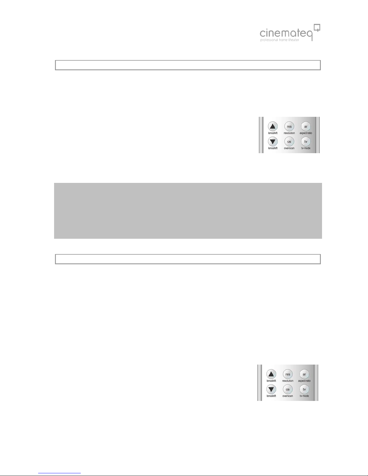
The choice of the desired aspect ratio is made by the key [ar]::
(1) Press the key [ar].
(2) In the display and/or On-screen the menu "aspect ratio" appears with the presently
active aspect ratio (e.g. "pass"). Press now [enter], the value is now deposited blue
and/or orange.
(3) Select with [+] / [-] keys the desired aspect ratio and activate these with [ enter] key.
(4) Repeated pressing of the key [ar] closes the menu "aspect ratio". Which format
transformation is active, see in the On-screen status info under the point "aspect
ratio"..
In the handbook appendix you will learn when which format change is best to use.
77
TV-MODE
The optimizing procedure has been exclusively designed for video signals in the so called “camera-“ and / or “video
mode“. This is video material recorded with digital video technology such as TV signals like sports broadcasts, concerts,
TV series etc.
The typical rendering problems such as fraying edges and “visible pixels” in moving objects are clearly reduced with the
“TV-Mode“.
The "TV mode" is activated and/or deactivated manually over the remote controll key
[tv].
In addition to that the “TV-Mode“ can also be preset for each input, i.e. you can define
in the input setup if the “TV Mode“ should be set to “on“ or “off“ for a certain input
(more on that in the following under “Input setup“).
However the “TV-Mode“ can – regardless of this preset – be switched off or on
manually. With every switching of inputs the preset for the according input is active
again.
Please note:
Every switching of an input, change of resolution, format conversion or switching off the device, will
automatically deactivate the “TV-Mode“, despite it is preset for a certain input via input setup.
ONLY use the “TV-Mode“ for video material in camera mode – with film material (e.g. cinema movies from
DVD) picture rendition is slightly deteriorated!
Whether the “TV-Mode“ is active or not, can be seen in the status info (press [Enter] key once).
OVERSCAN
As the perfect scaling of the picture optimizer plus HD (SDI) always renders the full picture content without “cut off” on
the edges, also errors on the picture edge are displayed, when watching “minor quality” signals (e.g. TV signals), which
are normally outside the viewable area e.g. when viewing on a standard TV device.
With the function "Overscan" one can variable from 99% to 70% "zoom" into the picture, i.e. 1% to 30% of the edge
is "cut" and the remaining picture content is increased on the full output quantity. Particularly with TV stations signal and
old video material this function guarantees an optimal representation of the picture content without disturbing "flutter
lines" in the boundary regions.
Usually "Overscan" is implemented symmetrically, i.e. horizontal and vertically directly, - it works thus like a symmetrical
zoom. The Overscan can optional be adjusted in addition, horizontal and vertically separately. Thus adjusts errors in
picture geometry (e.g. with a 15:9-Monitor) or will produce user-defined display formats.
The function "Overscan" (default value Overscan H & V = 100%) is switched over the
key [ OS ] on and/or off. Additionally can be switched by key combination [ option A ] +
[ OS ] between "symmetrical Overscan" (ON V=H) and "separately adjusted Overscan"
(ON V/H)..
The setting of the Overscan value from 100% to 70% is made by the Input-Setup
menu, more in addition under "Input Presettings" starting from page 79.

78
Just as the "TV mode", the desired "Overscan" can also be pre-defined for each input, i.e. in the Input-Setup is
deposited, whether during this input the "Overscan" is to stand on "OFF", on ON V=H or on ON V/H, and how much the
picture is "zoomed in" and/or the edge is cut away. More to it under "input Presettings" starting from page 33.
Naturally the Overscan can despite this pre-setting also be manually switched. After each switching the pre-setting of the
respective input is however again active.
Please note:
Whether the "Overscan" function is activated or not, can be called up by the status info. ( press [enter ] key.
By activating the function "Overscan" you leave the "perfect" scaling. With signals with picture errors at the
edge this is however an acceptable compromise.
Additional application type of the "Overscan" function is offered with 21:9 films on 16:9 display-device
and/or screens: With a Overscan of 75% it can become "zoomed in" accurately so far into the picture, that
the black bars from the picture disappear. Disadvantage is natural that the left and right contour in same
way becomes "cut off".
Table of contents


