Cineo Quantum c80 User manual
User Guide
Revision 1.2 — October, 2017
Information and specications in this document are
subject to change without notice.
www.cineolighting.com
2
Cineo has designed the ultimate creative
lighting tool: the Quantum c80. Combining the
same award-winning white light quality used in
Quantum 120 with innovative saturated color
technology, the Qc80 delivers up to 50,000 lumens
of beautiful, easily controllable, full-gamut light
across a diused 2’x 4’aperture. With built in power
supply and silent operation, the Qc80 delivers 1000
watts of power in a package that is less than 50 lbs
and is less than 6 inches deep.
Creating beautiful white light with extended color
gamut in smart packaging is only part of the story.
Cineo has also developed an intuitive control
strategy that allows predictable, repeatable results,
either using the graphic on board control panel
or remotely with wired or built-in wireless CRMX
control.
The strategy for control is simple. Whether using
local or DMX settings, four independent controls
(Dim, White, Saturation and Color) give range to
the entire xture via a single mode of intuitive
operation.
Dim
Uniform control of total xture output. Cineo’s
Photo-Accurate Dimming™ maps the 0-100%
dimming curve to actual camera stops for precise
output control using the DIM control locally or on
the rst DMX channel.
White
Adjust primary white light base 2700-6500K.
For color-accurate white light, choose the CCT as
you would with any Cineo xture, using the WHITE
rotary control or the second DMX channel.
Saturation
Blend between white light base and the color
gamut. This control blends and balances the
amount of saturated color with the CCT base, from
pristine white to deep artistic color. Also controlled
remotely on the third DMX channel.
Color
Explore brilliant color palettes across the full
color space. To optionally add saturated color, the
COLOR control adjusts the hue or on the fourth
DMX channel; the color of which is displayed on
the control panel.
With Qc80, the WHITE, COLOR and SATURATION
controls operate mutually exclusive from each
other, allowing for consistent color shading across
the entire range of white light bases. For example,
+2 Green added to 3200K CCT will look the same
as +2 Green at 5600K to the correctly white-
balanced camera.
In addition to Cineo’s proprietary phosphor-
converted white light LEDs, we have developed
phosphor-converted saturated color LEDs. The
phosphor-converted LEDs use the exact same dies
as the white LEDs, so all light emitting elements
of the c80 carry identical thermal stability, and
perform over time with identical dierential aging.
So after years of service, color stability remains
consistent.
The Quantum c80 is passively cooled for
completely silent operation, ruggedly built, water
resistant and includes an integrated power supply
for easy setup.
Welcome to Quantum c80 from Cineo

3
General Notes
1. Please read through this manual carefully before operating Cineo Qc80, and keep this manual
for future reference.
2. There are numerous safety instructions and warnings that must be adhered to for your
own safety.
3. Qc80 is not intended for residential use. It is intended for use in a professional studio.
4. Qc80 must be serviced by a qualied technician.
5. The Cineo Qc80 is rated as IP22 – for damp environments.
6. Cineo products are not certied for use in hazardous locations.
7. The Cineo Qc80 has a typical operating temperature of 50°C (122°F).
Fixture Set Up
Read these safety instructions carefully to ensure xture and accessories are used safely.
Ensure the junior mounting pin is correctly mounted onto the yoke before rigging.
Always use secondary safety cables of suitable length when hanging Cineo Qc80 units.
The Qc80 weighs 48 lbs. (22 kg) excluding accessories. The combined weight should be considered
when choosing a suitable safety cable.
Safety cables must securely be attached to the yoke on Qc80 or the safety holes located in each corner
and be as short as possible to reduce travel distance if primary hanging accessory fails.
Ensure that the yoke lock is correctly tightened when manipulating Qc80 in the required orientation for
safety purposes.
Ensure the Cineo Qc80 is operated within an ambient temperature range of -20 to +50°C (-4 to 122°F).

4
System Components, Connections and Controls
All connectors and system controls for the Cineo Qc80 are located on the back of the unit. In addition to
its full color heads-up display, optically encoded rotary knobs give access to menu selections and local
control inputs. Hard power connections and switches allow for easy set up and strike. The 5 pin DMX
connections, embedded wireless receivers, RDM responders and powered USB ports support many
options for external control.
Front
DMX
Connectors
USB Port
AC Power In, Fuse
and Power Switch
Back
5
Power
The Qc80 unit is controlled by an internal power supply. 110 – 220VAC is provided to the unit via a
locking IEC connector, located on the back control panel.
NOTES:
1. Ensure the power cable is disconnected before servicing.
2. Do not connect to a variable supply, such as a dimmer rack.
3. The power cable should be plugged into the power supply before switching the power ON. The power
supply should be switched OFF before removing the power cable.
4. A fuse is located within the IEC connection port. A spare fuse is provided in this same space. If power
is provided, the power switch is ON and the LED light on the power switch is not illuminated, please
disconnect power and check this fuse rst.
Displays Screens
The Qc80 control interface includes two backlit displays, each of which communicates valuable yet
discrete information during the operation and setup of the Qc80. They are separated as CONTROL and
STATUS.
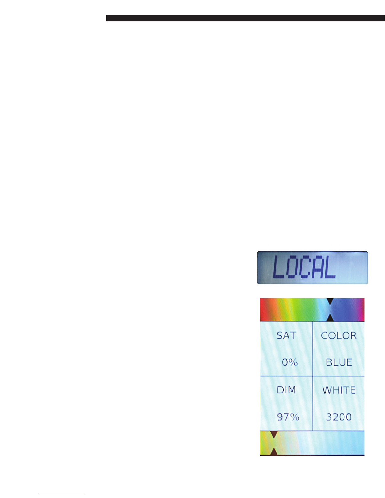
Control Screen
The Control screen is an 8-character, daylight-visible
display that shows data adjustment values in Local Mode,
shows DMX signal status in DMX Mode, Radio, Calibrate
and interacts with the Status screen in Menu Mode.
Status Screen
A full-color screen displays the status of each DIM, WHITE,
SATURATION and COLOR control value at all times. The color
ribbons on the top and bottom of the display give a visual
reference for both the WHITE CCT and the COLOR hue. DIM
value and SATURATION are represented as a percentage. In
DMX mode, this display reects the current DMX channel
assignment as well as the correlated values for each of the
four channels.
6
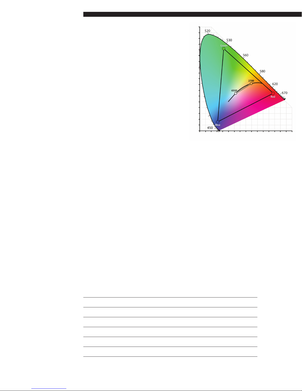
Color Space
The Qc80 uses two separate LED engines to
independently generate accurate white light, variable
from 2700K to 6500K, and an extended RGB gamut
for broad saturated color space. The CIE 1931 diagram
below illustrates the Qc80 color space.
Controls
Setup of the Qc80 is can be accomplished either
using the large Red DIM knob with the control and
status displays, or remotely using RDM.
Accessing the Setup Menu
The xture can be set up via the control panel as follows the follows:
1. Push and hold the larger Red knob for approximately 3 seconds. The status display will now show the
top level menu options.
2. Turn the Red knob until the desired control selection is highlighted: LOCAL, DMX, RADIO or CALIBRATE.
3. Push the knob again to select menu category.
Local Mode
When LOCAL mode is selected, all functions of the xture are managed through the 4 multi colored
rotary encoders and feedback is displayed on the display screens. The Control screen contextually
switches to show the value of each control being adjusted.
RED knob: Photo-Accurate Dimming
The dimming curve on the Qc80 follows a new strategy that provides relative output levels that
correspond to image capture. Both DMX values and local control levels directly correlate to camera stops
in a meaningful way. The result is extremely predictable light levels within the full output range of the
xture.
0-100% dimming is controlled by turning the Red rotary knob. Pushing the knob cycles the output at
these levels: 20%, 40%, 60%, 80% and 100%.
The following table shows the relationship between Local values as they relate to camera stops:
Local Value % Output increase Stop Increase
(0-100)
20% 100 0
40% 200 1
60% 400 2
80% 800 3
100% 1600 4

7
Here are examples of how to accurately match camera stops to dimming levels in Local Mode:
Local Dimming: The Rule of 20 (0-100 scale)
Increase output 1 Stop: Add 20 units (fc/lux is doubled)
Decrease output 1 Stop: Subtract 20 units (fc/lux is reduced 50%)
Adjust ½ Stop = 10 Units (0-100)
Adjust ¼ Stop = 5 Units (0-100)
Yellow Knob: CCT Adjustment
The color temperature (CCT) of the xture is controlled by turning the Yellow knob in a continuously
variable range of 2700K to 6500K. Pushing the Yellow control knob cycles the CCT of the xture between
popular settings: 2700, 3200, 4300, 5600 and 6500K.
Blue Knob: Color Saturation
The SATURATION of color added to the base white light is controlled by the Blue knob, which has presets
at 0%, 10%, 20%, 50%, 80% and 100%. Note that the addition of saturated color does not change the base
CCT of the white light; these are completely independent functions.
Green Knob: Color Control
The COLOR knob adjusts the hue of the saturated color system, which is added to the white light in
percentages, from 0% to 100% saturated color. The Green knob adjusts the saturated color hue, in 256
increments, and the approximate hue is displayed on the color ribbon. Pushing the Green knob cycles
between the primary and secondary colors: Red, Yellow, Green, Cyan, Blue and Magenta. Colors can be
ne-tuned anywhere within the color space.
The Status display shows all values selected for these four controls at all times.
DMX Mode
When DMX is selected from the menu, the output level, CCT, hue and saturation of the xture are
controlled remotely on four DMX addresses in the address range of 001 to 512. The left knob is used to
set the master DMX address for dimming; other three controls are automatically addressed sequentially.
The Control Display shows the master address of the xture while the addresses are being selected. When
the desired master address is selected, push the Red knob to save and enter DMX mode. The selected
addresses are shown on the Status Display for each function, and the Control Screen shows the status of
the DMX signal: DMX LINE, DMX WIFI or DMX NONE.
DMX Value % Output increase Stop Increase
(0-255)
50 100 0
100 200 1
150 400 2
200 800 3
250 1600 4

8
Here are examples of how to accurately match camera stops to dimming levels in DMX Mode:
DMX Dimming: The Rule of 50 (0-255 scale)
Increase output 1 Stop: Add 50 DMX values (fc/lux is doubled)
Decrease output 1 Stop: Subtract 50 DMX values (fc/lux is reduced 50%)
Adjust ½ Stop = 25 DMX Values
Adjust ¼ Stop = 12 DMX Values
The following table lists all the preset values in their DMX addresses for all of the preset values:
Dimming CCT Saturation Color
100% 255 2700 000 0% 000 Red 000/255
-1 Stop 200 3200 034 10% 025 Yellow 043
-2 Stops 150 4300 107 20% 050 Green 085
-3 Stops 100 5600 195 50% 128 Cyan 127
-4 Stops 050 6500 255 80% 204 Blue 170
O 000 100% 255 Magenta 212
Note that changing the DMX values in steps of 1 to 40 units will include a dimming hysteresis, or
smoothing. When switching between DMX values of 40 or greater, the value change is instantaneous,
allowing the xture to be externally switched on and o in a strobe eect.
Radio Mode
By selecting the RADIO function from the menu, the Radio submenu is displayed. From here, you can
either choose to Unlink the xture’s radio from its previous transmitter pairing, or turn the radio o. Push
the Red knob to perform the selected radio function.
Calibration
The Qc80 should periodically be calibrated to re-align all controls to their proper settings. When Calibrate
is highlighted on the menu and selected with the Red knob push, the xture will perform a self-
calibration routine, lasting approximately one minute and then return to its previous operating status.
Connections
Wired DMX Connections
Qc80 uses industry-standard 5-Pin XLR male and female connectors to receive and forward DMX
signals and output RDM signals. The DMX port is self-terminating and does not require external DMX
termination when used in a chain. If the unit is the last device on a DMX chain, make sure that there is no
cable inserted into the DMX Out connector.

9
The DMX pin wiring is as follows:
• Pin 1: Signal Common
• Pin 2: Data –
• Pin 3: Data +
• Pin 4: Spare
• Pin 5: Spare
Wireless DMX Control
The Qc80 built-in wireless receiver runs on CRMX / Lumen Radio protocol which can receive signals from
CRMX and some WDMX transmitters. Please note that each xture can only be linked to a single network
at a time, and maintains the network ID of its previous linking. Therefore, the xture’s linking data must be
cleared prior to linking to a new network.
To unlink Qc80 xture, follow these steps:
1. Push and hold the Red control knob on the control panel for 3 seconds. Release.
2. Rotate the Red knob until the Status Display shows RADIO highlighted. Push to select.
3. Make sure the UNLINK menu option is highlighted, and select. The Control Display will ash for 10
seconds, and the Radio is ready for linking to a transmitter, clearing the network memory in the xture.
To link to a new transmitter, make sure the xture is unlinked, in DMX mode and the DMX addresses are
set.
If the unit is in DMX Mode and no cable is inserted in the DMX IN port, Wireless DMX is automatically
activated and the unit can now be controlled on a linked wireless DMX network. When the unit is ready
to receive a signal from a transmitter but is not yet linked, the CONTROL screen will ash “DMX NONE.”
Once the connection is made the CONTROL Screen will change to “DMX WIFI” and can now be control
remotely.
Refer to your wireless DMX transmitter instructions for linking xtures to a wireless network.
Third party wireless products can be used by plugging the third party wireless antenna into the DMX XLR
port. If power is needed for the antenna the powered USB port can provide such up to 500ma@ 5VDC. If
a third party wireless device, powered or non powered, is attached via the 5pin XLR port this connection
will take priority over the imbedded wireless receiver.
RDM Support
The Qc80 can remotely report unit information to an RDM controller attached via wired or wireless DMX.
The information provided includes the Unit ID and the rmware revision programmed into the unit. The
unit also supports the RDM Identify command, and will ask the xture when an Identify command is
issued.
Remote programming of Mode, DMX address and Calibrate functions are supported. The xture defaults
to a 4-address footprint for RDM auto-assign functions.

10
USB Port
An A-type USB port is included on the control panel for installation of software updates. It can also
supply 5 VDC, 500ma power to attached devices. Refer to installation instructions supplied with software
upgrade.
Mounting Options
In addition to the attached mounting yoke, (4) attachment points are included of the back of the xture.
All of these points can accept a 3/8”x 16 threaded eyebolt. All of these attach points are safety rated.
Specications
Input Power: 110-240VAC, 1000 watts max. via locking IEC connector
Integrated power supply
Fixture Size: 24”x 48” x 5.5” (.6m x 1.2m x 14cm)
Diuser Size: 48”x 48” x 6”
Weight: 48 lbs. (22 kg.)
Mounting yoke includes Junior pin
Variable saturated color with presets at Red, Yellow, Green, Cyan, Blue, Magenta
Variable white/color blending
Local and Remote dimming, 0-100%
5-pin wired DMX/RDM In and Thru
Integrated LumenRadio™ CRMX bi-directional wireless DMX/RDM
Completely icker-free operation
Silent, passive cooling: no fans
Environmental temperature range: -20ºC - +50º C
Max. temperature rise: +45º C
ETL, cETL, CE pending
Made in USA

11
Warnings, Disclaimers and Warranty
Risk of Electric shock / Risk of Fire
Do not open. To reduce the risk of electric shock, do not remove cover (or back). No user-
serviceable parts inside. Refer servicing to qualified service personnel.
Burning Injuries
Be aware of high temperatures in excess of 50°C inside the fixture during and after use. Do
not touch the LEDs to avoid burning injuries.
Flammable Materials
Keep flammable materials away from the installation. Insure that the amount of air flow
required for safe operation of the equipment is not compromised. Proper ventilation must be
provided.
ESD and LED’s
LED components used in Quantum120 are ESD (Electro-Static Discharge) sensitive. To
prevent the possibility of destroying LED components do not touch either while in operation or
when switched off.
This Equipment MUST be Grounded
In order to protect against risk of electric shock, the installation should be properly grounded.
Defeating the purpose of the grounding type plug will expose you to the risk of electric shock.
AC Power Cords
Use only a rated IEC Connector. The user is responsible for ensuring power cables are of
adequate condition for each application. If the power cords are damaged, replace them only
with new ones.
Environmental: Disposal of Old Electrical & Electronic Equipment
This product shall not be treated as household waste.

12
CINEO LIGHTING LIMITED WARRANTY
Products from Cineo Lighting are warranted against defects in materials and workmanship
for two years from the date the Product is shipped to Customer. Products are guaranteed
to perform substantially in accordance with the accompanying written materials within the
warranty period under normal use.
If the Product fails to work as warranted, Cineo Lighting will, in its sole discretion, repair or
replace the Product with a new or remanufactured Product that is at least equivalent to the
original Product. Customer must obtain a Return Material Authorization number from Cineo
Lighting before returning any Products under warranty to Cineo Lighting.
Customer shall pay expenses for shipment of repaired or replacement Products to Cineo
Lighting’s repair facility. Any repaired or replaced Products will be warranted for the remainder
of the original warranty period or thirty (30) days, whichever is longer. Cineo Lighting will
pay shipping of repaired goods back to the customer. After examining and testing a returned
product, if Cineo Lighting concludes that a returned product is not defective, Customer will be
notified, the product returned at Customer’s expense.
This Limited Warranty is void if failure of the Products has resulted from accident, abuse,
misapplication, or use outside of normal operating conditions. Warranty is void if serial number
has been defaced or removed.
NO OTHER WARRANTIES. EXCEPT AS EXPRESSLY SET FORTH ABOVE, THE
PRODUCTS ARE PROVIDED “AS IS” WITHOUT WARRANTY OF ANY KIND, AND NO
OTHER WARRANTIES, EITHER EXPRESSED OR IMPLIED ARE MADE WITH RESPECT
TO THE PRODUCTS, INCLUDING BUT NOT LIMITED TO ANY IMPLIED WARRANTIES
OF MERCHANTABILITY, FITNESS FOR A PARTICULAR PURPOSE, TITLE OR NON-
INFRINGEMENT OR ANY OTHER WARRANTIES THAT MAY ARISE FROM USAGE OF
TRADE OR COURSE OF DEALING. ELEMENT DOES NOT WARRANT, GUARANTEE, OR
MAKE ANY REPRESENTATIONS REGARDING THE USE OF OR THE RESULTS OF THE
USE OF THE PRODUCTS IN TERMS OF CORRECTNESS, ACCURACY, RELIABILITY, OR
OTHERWISE AND DOES NOT WARRANT THAT THE OPERATION OF THE PRODUCTS WILL
BE UNINTERRUPTED OR ERROR FREE. CINEO LIGHTING EXPRESSLY DISCLAIMS ANY
WARRANTIES NOT STATED HEREIN. NO LIABILITY FOR CONSEQUENTIAL DAMAGES.
TO THE MAXIMUM EXTENT PERMITTED BY APPLICABLE LAW, IN NO EVENT SHALL
ELEMENT AND ITS LICENSORS, DISTRIBUTORS, AND SUPPLIERS (INCLUDING ITS
AND THEIR DIRECTORS, OFFICERS, EMPLOYEES, AND AGENTS) BE LIABLE FOR ANY
DAMAGES, INCLUDING, BUT NOT LIMITED TO, ANY SPECIAL, DIRECT, INDIRECT,
INCIDENTAL, EXEMPLARY, OR CONSEQUENTIAL DAMAGES, EXPENSES, LOST PROFITS,
INSTALLATION COSTS, LOST SAVINGS, BUSINESS INTERRUPTION, LOST BUSINESS
INFORMATION, OR ANY OTHER DAMAGES ARISING OUT OF THE USE OR INABILITY
TO USE THE PRODUCTS, EVEN IF ELEMENT OR ITS LICENSORS, DISTRIBUTORS, AND
SUPPLIERS HAS BEEN ADVISED OF THE POSSIBILITY OF SUCH DAMAGES. CINEO
LIGHTING’S TOTAL LIABILITY ON ALL CLAIMS, WHETHER IN CONTRACT, WARRANTY,
TORT (INCLUDING NEGLIGENCE OR BREACH OF STATUTORY DUTY), STRICT LIABILITY
OR OTHERWISE, SHALL NOT EXCEED THE AMOUNTS PAID BY CUSTOMER FOR THE
PRODUCTS.
Customer acknowledges that the applicable purchase price or license fee for the Products
reflects this allocation of risk. Because some states/jurisdictions do not allow the exclusion
or limitation of liability for consequential or incidental damages, the above limitation may not
apply. The above limitations shall apply notwithstanding the failure of any limited remedy to
fulfill its essential purpose.
www.cineolighting.com
Specifications are subject to change
without notice. Cineo Lighting, Cineo
Quantum c80 are registered trademarks
of Cineo Lighting, Inc.
©2017 Cineo Lighting, Inc. v11.15.17
Cineo Lighting
P.O. Box 808
El Granada, CA 94018
Silicon Valley | Los Angeles | London
+1 310.425.3425
Table of contents


