Starway Dino User manual

User manUal
www.star-way.com version 19032020 V1.0.4

Page 2 Page 3
Table of content
Technical Specications ....................................................3
Introduction ...................................................................3
Dimensions ....................................................................4
Regulation and Safety .......................................................5
Spectrometry .................................................................7
DMX Connection ........................................................... 11
Menu .........................................................................12
Gobo Wheel..................................................................18
DMX Map.....................................................................20

Page 2 Page 3
Technical specications:
Source: 200W white LED - 15700 ° K
Illumination at 5 m:
- 6400 Lux @ 11.5 °
- 4950 Lux @ 18 °
- 3150 Lux @ 24 °
Luminous ux max. : 8000 Lumens
10 ° -25 ° zoom
DMX modes: 14/17/20 Channels
Mode: Static, Auto, DMX
Max consumption : 280W (@ 220V)
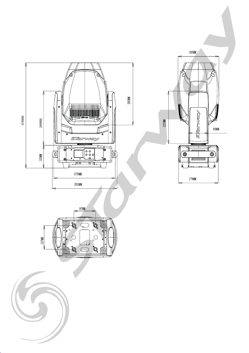
Dimensions: 292 x 474 x 185 mm
Weight: 11.5 kg
IP20
Introduction:
This product has been dedicated for indoor use only.
Particularly suitable for scenes. TV set or discos.
Controllable in DMX these projectors can be controlled by
any DMX console.
Page 4 Page 5
DIMENSIONS (mm) :
474MM
244MM103MM
280MM
185MM
89MM
237MM
179MM
97MM
107MM
278MM
292MM

Page 4 Page 5
WARNING! Before carrying out any operations with the unit,
carefully read this instruction manual and keep it with cure
for future reference. It contains important about the installation,
usage and maintenance of the unit.
SAFETY
General InstrUctIon
• The products referred to in this manual conform to the European Community
Directives and are there-fore marked with CE:.
• The unit is supplied with hazardous network voltage (230V~). Leave servicing
to skilled personnel only. Never make any modications on the unit not de-
scribed in this instruction manual, otherwise you will risk an electric shock.
• Connection must be made to a power supply system tted with efcient earth-
ing (Class I appliance ac-cording to standard EN 60598-1 ). It is, moreover,
recommended to protect the supply lines of the units from indirect contact
and/or shorting to earth by using appropriately sized residual current devices.
• The connection to the main network of electric distribution must be carried out
by a qualied electrical installer. Check that the main frequency and voltage
correspond to those for which the unit is designed as given on the electrical
data label.
• Never use the xture under the following conditions:
- in places wet;
- in places subject to vibrations or bumps;
- in places with an ambient temperature of over 45° C.
• Make certain that no inammable liquids, water or metal objects enter the
xture.
• Do not dismantle or modify the xture.
• All work must always be carried out by qualied technical personnel. Contact
the nearest sales point for an inspection or contact the manufacturer directly.
• If the unit is to be put out of operation denitively, take it to a local recycling plant
for a disposal which is not harmful to the environment.
WarnInGs and InstallatIon precaUtIons
• Never let the power cord come into contact with other cables! Handle the power
cord and all connections with the mains with particular caution!
• Never modify, bend, mechanically strain, put pressure on, pull or heat up the
power cord.
• Never strain the cable. There must always be sufcient cable going to the device.
Otherwise, the cable will be damaged, which can cause serious damage.
• Never remove warning or informative labels from the unit.
• Never use anything to cover the ground contact.
• Never lift the device holding it by the projector-head, as the mechanics may be
damaged
• Do not shake the device. Avoid brute force when installing or operating the device.
• Only operate the device after having checked if the housing is rmly closed and all
screws are tightly fastened.
• Only operate the device after having familiarized with its functions.
• Avoid ames and do not put close to ammable liquids or gases.
• Always allow a free air space of at least 0.8 m around the unit for ventilation.
• Always disconnect power from the mains, when device is not used or before
cleaning! Only handle the power cord holding it by the plug. Never pull out the plug
by tugging the power cord.

Page 6 Page 7
• Make sure that the device is not exposed to extreme heat or dust.
• Make sure that the available voltage is not higher than stated on the rear panel.
• Make sure that the power cord is never crimped or damaged. Check the device
and the power cord from time to time.
• Make sure that the core diameter of extension cords and power cords is suf-
cient for the required power consumption of the device.
• Always hold the device by the transport handles.
• Never place any material over the LEDs or lens.
• Never look directly into the light source.
• Never leave any cables lying around.
• Never use the device during thunderstorms, unplug the device immediately.
• Never leave various parts of the packaging (plastic bags, polystyrene foam, nails,
etc within children’s reach, as they potential sources of danger.
• Do not insert objects into air vents.
• Do not open the device and do not modify the device.
• Do not connect this device to a dimmer pack.
• Do not switch the device on and off in short intervals, as this will reduce the
device’s life.
• Do not touch the device’s housing bare-handed during its operation (housing be-
comes very hot). Allow the device to cool for at least 5 minutes before handling.
• If the lens or LEDs are obviously damaged, they need to be replaced to prevent
their functions from being impaired, due to cracks or deep scratches.
• If the external cable is damaged, it has to be replaced by a qualied technician.
• If device was dropped or struck, disconnect mains power supply immediately.
Have a qualied engineer inspect for safety before operating.
• If the device has been exposed to drastic temperature uctuation (e.g. after
transportation), do not switch it on immediately. The arising condensation water
might damage your device. Leave the device switched off until it has reached
room temperature.
• If your device fails to work properly, discontinue the use immediately. Pack the unit
securely (preferably in the original packing material), and return it to your dealer
for service.
• For adult use only. The device must be installed beyond the reach of children.
Never leave the unit running unattended.
• Never attempt to bypass the thermostatic switch or fuses.
• For replacement use fuses of same type and rating only.
• This device is heavy. When handling, use a two-person lift to prevent injury.
• The user is responsible for correct positioning and operating of the device. The
manufacturer will not accept liability for damages caused by the misuse or incor-
rect installation of this device.
• This device falls under protection class I. Therefore it is essential to connect the
yellow/green conductor to earth.
• Repairs, servicing and electric connection must be carried out by a qualied
technician.
Rigging
This device is heavy. When handling, use a two-person lift to prevent injury.
Please follow the European and national guidelines concerning rigging, truss-
ing and all other safety issues.

Page 6 Page 7
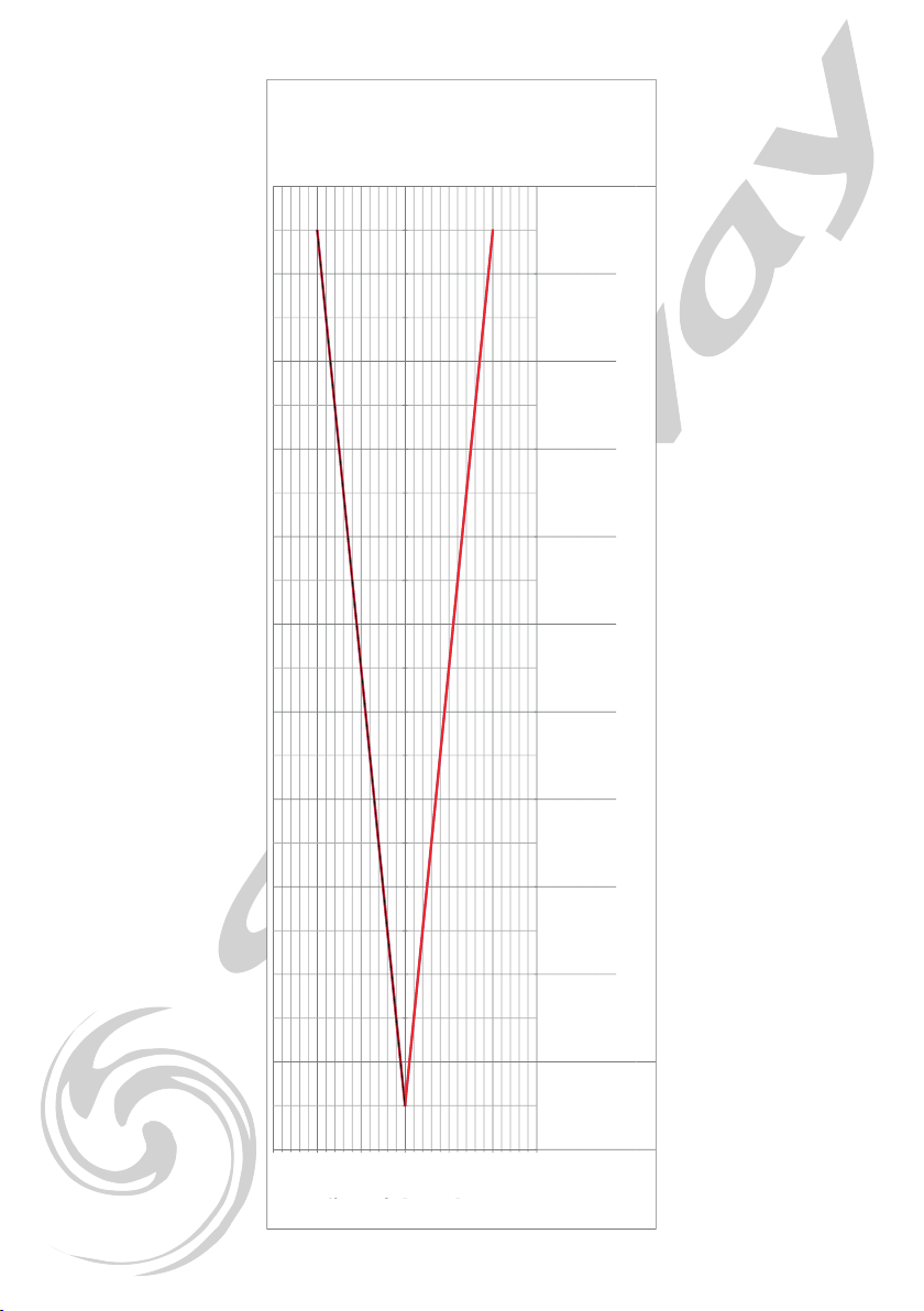
SPECTROMETRY
Distance 5 meters
Lux
White LED 11,5° 6400 lux
White LED 18° 4950 lux
White LED 24° 3150 lux
MeasureMents Made with uspectruM MK305s
Page 8 Page 9
° Beam: ####
° Field: ####
Eclaire
m
##### 40044 17797 10011 6407 4449 3269 2503 1977 1602 1324 11129 48 8177 12 6265 54 4944 44 400
Distance en 12345678 91 01 11 21 31 41 51 61 71 81 92 0
D Be
a
0.20 .4 0.60 .8 11 .2 1.41 .6 1.82 2.22 .4 2.62 .8 33 .2 3.43 .6 3.84
D Fie0 .2 0.40 .6 0.81 1.21 .4 1.61 .8 22 .2 2.42 .6 2.83 3.23 .4 3.63 .8 4
00 .1 0.20 .3 0.40 .5 0.60 .7 0.80 .9 11 .1 1.21 .3 1.41 .5 1.61 .7 1.81 .9 2
00 .1 0.20 .3 0.40 .5 0.60 .7 0.80 .9 11 .1 1.21 .3 1.41 .5 1.61 .7 1.81 .9 2
0- 0.1- 0.2- 0.3- 0.4- 0.5- 0.6- 0.7- 0.8- 0.9- 1- 1.1- 1.2- 1.3- 1.4- 1.5- 1.6- 1.7- 1.8- 1.9- 2
0- 0.1- 0.2- 0.3- 0.4- 0.5- 0.6- 0.7- 0.8- 0.9- 1- 1.1- 1.2- 1.3- 1.4- 1.5- 1.6- 1.7- 1.8- 1.9- 2
-1.5
-1
-0.5
0
0.5
1
1.5
D Field en metres 0.20 .4 0.60 .8 11 .2 1.41 .6 1.82
D Beam en metres 0.20 .4 0.60 .8 11 .2 1.41 .6 1.82
Distance en metres 123 456 78 91 0
Eclairement Lux1 601754 0044 177971 0011 6407 4449 3269 2503 1977 1602
° Field: 11.42
° Beam: 11.42
R
a
y
o
n
e
n
m
e
t
r
e
s
Angle Field
Angle Beam
11°
D Field in meters
D Beam in meters
Distance in meter
lllumination
Radius in meters

Page 8 Page 9
18°
° Beam: ####
° Field: ####
Eclaire
m
##### 30856 13714 7714 4937 3428 2519 1929 1524 1234 10208 57 7306 30 5494 82 4273 81 342 309
Distance en 12345678 91 01 11 21 31 41 51 61 71 81 92 0
D Be
a
0.30 .6 0.91 .2 1.51 .8 2.12 .4 2.73 3.33 .6 3.94 .2 4.54 .8 5.15 .4 5.76
D Fie0 .320 .640 .961 .281 .6 1.92 2.24 2.56 2.88 3.23 .523 .844 .164 .484 .8 5.12 5.44 5.76 6.08 6.4
00 .150 .3 0.45 0.60 .750 .9 1.05 1.21 .351 .5 1.65 1.81 .952 .1 2.25 2.42 .552 .7 2.85 3
00 .160 .320 .480 .640 .8 0.96 1.12 1.28 1.44 1.61 .761 .922 .082 .242 .4 2.56 2.72 2.88 3.04 3.2
0- 0.2- 0.3- 0.5- 0.6- 0.8- 0.9- 1.1- 1.2- 1.4- 1.5- 1.7- 1.8- 2- 2.1- 2.3- 2.4- 2.6- 2.7- 2.9- 3
0- 0.2- 0.3- 0.5- 0.6- 0.8- 1- 1.1- 1.3- 1.4- 1.6- 1.8- 1.9- 2.1- 2.2- 2.4- 2.6- 2.7- 2.9- 3- 3.2
-2
-1.5
-1
-0.5
0
0.5
1
1.5
2
D Field en metres 0.32 0.64 0.96 1.28 1.61 .922 .242 .562 .883 .2
D Beam en metres 0.30 .6 0.91 .2 1.51 .8 2.12 .4 2.73
Distance en metres 1234567 89 10
Eclairement Lux1 234253 0856 137147 7144 9373 4282 5191 9291 5241 234
° Field: 18.18
° Beam: 17.06
R
a
y
o
n
e
n
m
e
t
r
e
s
Angle Field: °
Angle Beam: °
D Field in meters
D Beam in meters
Distance in meter
lllumination
Radius in meters
Page 10 Page 11
24°
° Beam: ####
° Field: ####
Eclaire 78725 19681 8747 4920 3149 2187 1607 12309 72 7876 51 5474 66 4023 50 3082 72 2432 18 197
Distance en 12345678 91 01 11 21 31 41 51 61 71 81 92 0
D Be 0.36 0.72 1.08 1.44 1.82 .162 .522 .883 .243 .6 3.96 4.32 4.68 5.04 5.45 .766 .126 .486 .847 .2
D Fie0 .420 .841 .261 .682 .1 2.52 2.94 3.36 3.78 4.24 .625 .045 .465 .886 .3 6.72 7.14 7.56 7.98 8.4
00 .180 .360 .540 .720 .9 1.08 1.26 1.44 1.62 1.81 .982 .162 .342 .522 .7 2.88 3.06 3.24 3.42 3.6
00 .210 .420 .630 .841 .051 .261 .471 .681 .892 .1 2.31 2.52 2.73 2.94 3.15 3.36 3.57 3.78 3.99 4.2
0- 0.2- 0.4- 0.5- 0.7- 0.9- 1.1- 1.3- 1.4- 1.6- 1.8- 2- 2.2- 2.3- 2.5- 2.7- 2.9- 3.1- 3.2- 3.4- 3.6
0- 0.2- 0.4- 0.6- 0.8- 1.1- 1.3- 1.5- 1.7- 1.9- 2.1- 2.3- 2.5- 2.7- 2.9- 3.2- 3.4- 3.6- 3.8- 4- 4.2
-2.5
-2
-1.5
-1
-0.5
0
0.5
1
1.5
2
2.5
D Field en metres 0.42 0.84 1.26 1.68 2.12 .522 .943 .363 .784 .2
D Beam en metres 0.36 0.72 1.08 1.44 1.82 .162 .522 .883 .243 .6
Distance en metres 12 345 67 89 10
Eclairement Lux7 8725 196818 7474 9203 1492 1871 6071 2309 72 787
° Field: 23.72
° Beam: 20.41
R
a
y
o
n
e
n
m
e
t
r
e
s
Angle Field: °
Angle Beam: °
D Field in meters
D Beam in meters
Distance in meter
lllumination
Radius in meters
Page 10 Page 11
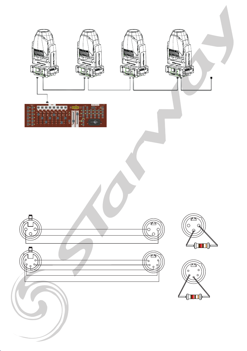
dmX connectIon:
The projectors are connected in series to a DMX console.
Connect the projectors as shown in the diagram above.
- Connect the male side of the DMX cable to the output of the DMX512 console.
- Then connect the DMX output of the projector to the input of the next projector.
- Repeat the operation on the whole chain.
The use of a termination plug is strongly recommended. In some cases the
absence of this termination is not problematic, on the other hand its presence
is very strongly recommended in disturbed spaces (Stage, long line length, TV
studio etc.). Its value is generally 120 Ohms. The plug is an XLR male plug into
which a resistance of 120 Ohms ¼ of W. is welded between 2 and 3. This plug
prevents the reection of information transmitted when using long lengths of
cable.
21
3
12
3
3
5
42
1
2
1
3
4
5
GND
DATA -
DATA +
GND
DATA +
DATA -
NOT CONNECTED
NOT CONNECTED
12
3
2
1
3
4
5
120 Ω
120 Ω
21
3
12
3
3
5
42
1
2
1
3
4
5
GND
DATA -
DATA +
GND
DATA +
DATA -
NON CONNECTE
NON CONNECTE
12
3
2
1
3
4
5
120 Ω
120 Ω

Page 12 Page 13
MENU
Menu SUB-Menu Option
Receive Set Address A001~AXXX
User Mode
User Mode
Standard (17 C) - (16bit)
Basic (14 C) - (8bit)
Extend (20 C) - (16bit)
User A
User B
User C
Edit A Max Channel
PAN, TILT, ....
:
Edit B
Edit C
Function
Status
No DMX Mode Hold/Auto/black
P.Reverse ON/OFF
T.Reverse ON/OFF
Pan Degree 630/540
Feedback ON/OFF
Move.Spd Speed 1~ 4
Hibernation OFF, 01M~99M
C.G.P Mode FS - Stop - SF
SF - Stop - FS
Temp. C/F Celsius °C
Fahrenheit °F
THE VALUES IN RED ARE DEFINED BY DEFAULT IN THE MENU
AND RELOADED AS IN THE CASE OF
«RELOAD DEFAULT SETTINGS»
Page 12 Page 13
Function
Dim Curve
Linear
Exp
Log
S-Curve
Frequency 900HZ/1000HZ/1100HZ/1200HZ/
1300HZ/1400HZ/1500HZ/2500HZ
Fan Set
Head Fan Auto
High
Low
LCD.Set
Backlight 02~60m <05m>
Flip Display ON/OFF
Key Lock ON/OFF
DispFlash ON/OFF
Disp.Set
Chan.Value PAN……
Slave Set Slave1,Slave2,Slave3
Auto.Prog Master / Alone
DFSE ON/OFF
Information
Time.Info
CurrentTime (HOUR)
Total Time (HOUR)
Last Clear (HOUR)
Timer PIN PIN CODE
Clear Last ON/OFF
Clear Total ON/OFF
T: XXXF
Fan Speed Fan1 : xxxxRPM
Fan2 : xxxxRPM
Error. Info NONE/Pan,Tilt…..
Model. Info 225700 - Dino
Software.V
1U01 V1.0.2
2U01 V1.0.2
3U01 V1.0.2
Page 14 Page 15
Test
Reset.Motor
All
Pan&Tilt
Head
Test.Channel
Pan, Pan Fine, Tilt, Tilt Fine, Color, Fixed Gobo,
Rotative Gobo, Gobo Rotation, Prism, PrismRot,
Strobe, Dimmer, Dim Fine, Zoom, Focus, Frost,
DimMode, P/T Speed.
Panel.Ctrl.
Pan, Pan Fine, Tilt, Tilt Fine, Color, Fixed Gobo,
Rotative Gobo, Gobo Rotation, Prism, PrismRot,
Strobe, Dimmer, Dim Fine, Zoom, Focus, Frost,
DimMode, P/T Speed.
PAN =XXX , ...
Calibrate Password 60
PAN, TILT, ...
RECEIVE MENU
Address set:
Dino DMX address conguration
USER MODE MENU
User Mode:
Selection of the DMX mode of the Dino between the different modes such as:
- Basic 14 DMX channels - 8-bit mode
- Standard 17 DMX channels - 16-bit mode
- Extended 20 DMX Channels - Extended 16-Bit Mode
- User A - User mode 1
- User B - User mode 2
- User C - User mode 3
Edit A; Edit B; Edit C
In this submenu it is possible to create 3 channel assignments at the user discretion. In
each “Edit A; Edit B and Edit C «it is possible to select the maximum number of channels,
and to change the order of the DMX channels.

Page 14 Page 15
FUNCTION MENU
Status
In this submenu it is possible to modify the behavior of the Dino.
No DMX Mode
Modication of the Dino reaction during DMX signal loss:
- Hold: maintenance of the last DMX values received
- Auto: The Dino goes into Auto mode
- Black Out: The Dino goes into “Stand By” mode
P Reverse: ON / OFF - Pan inversion
T Reverse: ON / OFF - Tilt inversion
PAN degree: 630 ° Or 540 ° - Selection of the maximum angle of PAN
(this value does not affect continuous rotation)
Feedback: ON / OFF - Activation or Deactivation of feedback
motors (Copy)
Move Speed: Selection of movement speed between 1 and 4
1 - faster to 4 - slower
Hibernation: OFF - 01 Min to 99 Min - Selection of hibernation mode
Dino. OFF by default or from 1 minute to 99 minutes before switching to
hibernation mode.
C.G.P Mode: Operation of the color wheel rotation,
gobos, gobos and prism. From Fast to Slow - Stop - from Slow to fast by default or in slow
to fast mode - Stop - From fast to slow to match version earlier than version 1.0.4
Temp C ° / F °
Submenu for selecting the Celsius or Fahrenheit system (default), for displaying the tempe-
rature.
Dim Curve
Submenu allowing the selection of the Dino dimmer curve between Curve 1 (default) and
Curve 4
Frequen
Submenu allowing the selection of the refresh rate of the LED to avoid a possible «icking»
during the capture. Changeable values between 900Hz (default) and 2500Hz.

Page 16 Page 17
Fan Set - Head Fan
Submenu for selecting the head fan speed between Auto (default) and Low or High.
LCD Set
Submenu allowing to select the behavior of the Dino display.
Backlight - 02m to 60m - Selection of the display backlight retention time (without menu
manipulation) from 2 minutes to 60 minutes. Time set to 5 minutes by default.
Flip Display - ON / OFF - Reversal of the display direction
KeyLock - ON / OFF - Lock the Dino buttons.
DispFlash - ON / OFF - Activation or not of the display ash when the Dino does not receive
a DMX signal.
Disp.Set
Chan.Value - continuously displays the DMX values of all channels.
Slave Set - Selection of the slave mode of the Dino to «shift» the Dino when
using the Master / Slave mode - between Slave 1, Slave2 and Slave 3.
Auto Prog - Selection of Master / Slave mode:
In MASTER mode the Dino transmits information to the Dino
connected using a DMX cable and where Slave mode has been activated
in the “Slave Set” submenu
In ALONE mode the Dino does not transmit information and executes
its AUTO mode individually.
DFSE - ON / OFF - Reloading the Dino default parameters.
INFORMATION
Time.Info
CurrentTime: Display of usage time (in hours) since the last power-up
TotalTime: Display of the usage time (in hours) since the rst power-up.
LastTime: Display of the usage time (in hours) since the last reset.
Time PIN: To access the reset of usage times you must enter a PIN code:
050 to reset the «CurrentTime»
060 to reset the «TotalTime»
ClearLast: ON / OFF to reset
Temp.Info - LED temperature display
T: xxx F or C - LED temperature display

Page 16 Page 17
Fan Speed - Fan speed display
Fan 1: xxx RPM
Fan 2: xxx RPM
Error.Info - Display of the last 10 error messages.
Model.Info - Model name display: 225700 - Dino
Software.V - Display of the version of the various processors
1U01 - Vx.x.x
2U01 - Vx.x.x
3U01 - Vx.x.x
TEST
Reset Motors
ALL: Reset of all motors
Pan & Tilt: Reset of Pan and Tilt motors
Head: Reset of all head motors
Test.Channel
Submenu allowing to test all the parameters of the Dino such as:
Pan, Pan Fine, Tilt, Tilt Fine, Color, Fixed Gobo, Rotative Gobo, Gobo Rotation, Prism,
PrismRot, Strobe, Dimmer, Dim Fine, Zoom, Focus, Frost, DimMode, P / T Speed.
Panel.Ctrl.
Pan, Pan Fine, Tilt, Tilt Fine, Color, Fixed Gobo, Rotative Gobo, Gobo Rotation, Prism,
PrismRot, Strobe, Dimmer, Dim Fine, Zoom, Focus, Frost, DimMode, P / T Speed.
Calibrate:
Submenu allowing to recalibrate the motors and the LED of the Dino
to access this menu, enter the PIN code for unlocking this function.
Pin Code: 060
This gives access to the different parameters:
Pan, Pan Fine, Tilt, Tilt Fine, Color, Fixed Gobo, Rotative Gobo, Gobo Rotation, Prism,
PrismRot, Strobe, Dimmer, Dim Fine, Zoom, Focus, Frost, DimMode, P / T Speed.
Page 18 Page 19
Rotating Gobo Wheel
Page 18 Page 19
Fixed Gobo Wheel

Page 20 Page 21
DMX Map
Basic Mode - 8 Bits
CHANNEL VALUES DESCRIPTION
1000-255 PAN
2000-255 TILT
3000-255 DIMMER 0% to 100%
4
SHUTTER
000-031 Shutter closed
032-063 Shutter open
064-095 Strobe slow to fast
096-127 Shutter open
128-159 Slow to fast pulse effect
160-191 Shutter open
192-223 Slow to fast random strobe
224-255 Shutter open
5
COLOR WHEEL
000-005 Open
006-011 Red
012-017 Orange
018-023 Yellow
024-029 Green
030-035 Dark Blue
036-041 Purple
042-047 Light Blue
048-053 Magenta
054-192 Colour Wheel Pos 0 - 360°
193-223 Color Wheel Rotation Fast to Slow, CW
224-224 Color Wheel Rotation Stop
225-255 Color Wheel Rotation Slow to Fast, CCW
6
ROTATING GOBO WHEEL
000~005 Open
006~020 Gobo 1
021~035 Gobo 2
036~050 Gobo 3
051~065 Gobo 4
066~080 Gobo 5
081~095 Gobo 6
096~110 Gobo 1 shake, from slow to fast
111~125 Gobo 2 shake, from slow to fast
126~140 Gobo 3 shake, from slow to fast
141~155 Gobo 4 shake, from slow to fast
153~170 Gobo 5 shake, from slow to fast
171~185 Gobo 6 shake, from slow to fast
186~192 Open
193~223 Gobo Wheel Rotation Fast to Slow, CW
224-224 Gobo Wheel Rotation Stop
225-255 Gobo Wheel Rotation Slow to Fast, CCW
Other manuals for Dino
1
Table of contents
Other Starway Dj Equipment manuals


Popular Dj Equipment manuals by other brands


Beamz
Beamz 3-SOME instruction manual

PR Lighting
PR Lighting XR480 BWS user manual

Beamz
Beamz Fuze 75 Beam user manual

thomann
thomann Stairville Crown FX PAR 77 user manual

MAX LIGHT
MAX LIGHT PartyBar11 instruction manual

Chauvet Professional
Chauvet Professional MAVERICK FORCE 3 PROFILE Quick reference guide