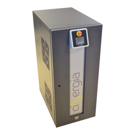
Cinergia GE+ Owner's manual

Grid Emulator (GE+ AC&DC)
Installation and operation manual

INDEX
1. INTRODUCTION ..................................................................................................................... 5
1.1. Symbols used ................................................................................................................. 5
1.2. Safety notes ................................................................................................................... 5
1.3. Quality and regulations ................................................................................................. 5
2. PRESENTATION ...................................................................................................................... 7
2.1. Introduction .................................................................................................................. 7
2.2. Power supply features................................................................................................... 9
2.3. Operation and connection modes .............................................................................. 10
2.4. Configuration and control of the power supply .......................................................... 11
2.5. Functional diagram ...................................................................................................... 11
2.6. Principle of operation .................................................................................................. 13
3. INSTALLATION AND WIRING RECOMMENDATIONS ........................................................... 17
3.1. Requirements and process to locate and fit in the equipment .................................. 17
3.2. Installation features .................................................................................................... 17
3.3. Isolation transformer .................................................................................................. 18
3.4. Case External Isolation Transformer with or without inrush current limitation box .. 21
3.4.1. OPTION A: WITH INRUSH CURRENT LIMITATION BOX ....................................... 21
3.4.2. OPTION B: WITHOUT INRUSH CURRENT LIMITATION BOX ................................ 21
3.5. Configuration values of protection and wires ............................................................. 23
3.6. Configuration values of suitable terminal metric ....................................................... 25
4. INSTALLATION ..................................................................................................................... 26
4.1. Important safety instructions ...................................................................................... 26
4.2. Equipment views ......................................................................................................... 26
4.3. Equipment reception................................................................................................... 30
4.3.1. Unpacking and checking the content .................................................................. 30
4.3.2. Storage ................................................................................................................ 30
4.3.3. Transport to location ........................................................................................... 30
4.3.4. Location ............................................................................................................... 30
4.4. Connection .................................................................................................................. 32
4.4.1. Earth protection .................................................................................................. 32
4.4.2. Input connection, terminals (X1 to X5). .............................................................. 32
4.4.3. External isolation transformer ............................................................................ 33
4.4.4. Output connection, terminals (X6 to X10 and X20 to X22) ................................. 34

4.4.4.1. AC mode (X6 to X10) ....................................................................................... 34
4.4.4.2. DC unipolar mode............................................................................................ 34
4.4.4.3. DC bipolar mode .............................................................................................. 34
4.4.5. Emergency Power Off terminals (X12) (EPO) ...................................................... 34
4.4.6. Output signal of local Emergency Stop pushbutton state (EPO OUTPUT) .......... 36
4.4.7. Communications ................................................................................................. 37
4.4.8. Digital inputs and outputs ................................................................................... 37
4.4.9. Analogue inputs and outputs (AIO) ..................................................................... 38
5. OPERATION ......................................................................................................................... 44
5.1. Safety ........................................................................................................................... 44
5.2. State Machine ............................................................................................................. 44
5.2.1. Initialization ......................................................................................................... 45
5.2.2. Standby ................................................................................................................ 45
5.2.3. Precharge ............................................................................................................ 46
5.2.4. Ready ................................................................................................................... 46
5.2.5. Run ...................................................................................................................... 46
5.2.6. Alarm ................................................................................................................... 46
5.3. Operation modes ........................................................................................................ 47
5.3.1. Constant Voltage (CV) ......................................................................................... 48
5.3.2. Constant current (CC) .......................................................................................... 49
5.3.3. Constant power (CP) ........................................................................................... 49
5.3.4. Constant impedance (CI) ..................................................................................... 49
5.3.5. Faults Generation (FG) ........................................................................................ 49
5.3.6. Independent branch control ............................................................................... 54
5.3.7. Power amplifier ................................................................................................... 55
5.4. Connection modes ...................................................................................................... 55
5.4.1. AC (Q4 in AC position) ......................................................................................... 56
5.4.2. DC (Q4 in DC position) ......................................................................................... 57
5.5. Working with the equipment ...................................................................................... 59
5.5.1. Start-up ................................................................................................................ 60
5.5.2. Stop ..................................................................................................................... 61
5.5.2.1. Full stop ........................................................................................................... 61
5.5.2.2. Standby stop .................................................................................................... 61
5.5.2.3. Ready ............................................................................................................... 62

5.5.3. Emergency stop ................................................................................................... 62
5.5.4. Accidental shut down .......................................................................................... 62
5.5.5. Alarms.................................................................................................................. 63
5.5.6. Alarms reset ........................................................................................................ 64
6. LOCAL TOUCHSCREEN CONTROL PANEL ............................................................................. 66
6.1. Upper bar .................................................................................................................... 66
6.2. Keyboard ..................................................................................................................... 67
6.3. LCD tabs distribution ................................................................................................... 68
6.3.1. Supervision .......................................................................................................... 69
6.3.2. Scada ................................................................................................................... 70
6.3.3. Alarms.................................................................................................................. 71
6.3.4. Plots ..................................................................................................................... 72
6.3.5. Settings ................................................................................................................ 73
6.3.6. Operational Panel ................................................................................................ 85
7. DIGITAL CONTROL ............................................................................................................... 87
8. REMOTE COMMUNICATIONS .............................................................................................. 88
9. HUMAN MACHINE INTERFACE ............................................................................................ 89
9.1. Show operational button ............................................................................................ 90
9.2. Distribution of the interface ........................................................................................ 92
9.2.1. Operation ............................................................................................................ 93
9.2.2. Alarm ................................................................................................................... 96
9.2.3. Supervision .......................................................................................................... 97
9.2.4. AC ........................................................................................................................ 98
9.2.5. DC ...................................................................................................................... 106
9.2.6. Limits ................................................................................................................. 113
9.2.7. Alarms Configuration ........................................................................................ 117
9.2.8. About ................................................................................................................. 119
10. WARRANTY AND MAINTENANCE .................................................................................. 120
10.1. Replacing the input fuses ...................................................................................... 120
10.2. Fans ....................................................................................................................... 120
10.3. DC bus capacitors .................................................................................................. 120
10.4. Warranty ............................................................................................................... 120
10.5. Claim procedure .................................................................................................... 121

GE+ ACDC Installation and operation manual v11
5 / 121
1. INTRODUCTION
Dear customer, on behalf of CINERGIA team, thank you for the confidence placed in our
company and for the purchase of this product. Please, read carefully this manual before using
the equipment to get familiarized with it and to obtain the maximum performance from it.
This document is intended for appropriately qualified personnel. Only personnel with the
appropriate skills are allowed to perform the electrical connection and commissioning of the
equipment.
The information in this documentation is not binding. CINERGIA reserves the right to make
changes in part or in the whole at any time and without prior notice due to technical advance or
product improvement.
1.1. Symbols used
DANGER: Indicates a hazardous situation which can result in death or serious
injury and can cause important damage or destruction of the equipment or the
property.
WARNING: Indicates important information that must be considered to operate
the equipment. Take the appropriate prevention measures.
INFORMATION: Information that is important but is not safety-relevant.
1.2. Safety notes
Improper use of this equipment can cause both important personal injury and physical damage
to the electrical power grid and the loads connected to it. Read this document carefully and
follow all safety precautions always.
1.3. Quality and regulations
The equipment is based on a hardware designed, manufactured and commercialized in
accordance with the standard EN ISO 9001 of Quality Management Systems. The marking shows
conformity to the EEC Directive by means of application of the following standards:
• 2006/95/EC Low voltage directive.
• 2004/108/EC Electromagnetic Compatibility directive (EMC)
In accordance with the specifications of the harmonized standards:
• EN-IEC 62040-1. Uninterruptible power supply (UPS). Part 1-1: General and safety
requirements for UPS’s used in accessible areas by end users.

GE+ ACDC Installation and operation manual v11
6 / 121
• EN-IEC 60950-1. IT equipment. Safety. Part 1: General requirements.
• EN-IEC 62040-2. Uninterruptible power supply (UPS). Part 2: Prescriptions for Electromagnetic
compatibility (EMC).
• EN-IEC 62040-3. Uninterruptible power supply (UPS). Part 3: Methods of operation
specification and test requirements.
The manufacturer responsibility is excluded in the event of any modification or intervention in
the product by the customer’s side.

GE+ ACDC Installation and operation manual v11
7 / 121
2. PRESENTATION
2.1. Introduction
As a grid emulator, the GE is a programmable power supply specially designed to emulate grid
disturbances. Its programmable parameters will allow the generation of different type of grids
and its common faults and disturbances. The main functionalities of the GE are the following:
- It converts the AC input, of the main grid, in a controlled programmable AC (optionally
also DC) output by using an IGBT-based switching topology and DSP-based state-of-the-
art digital control.
- It can generate different types of grids:
o Three phase power grid (3F+N) from 0 to 480 Vac (277Vrms f-n)
o One phase power grid (1F+N) from 0 to 277 Vrms f-n
o Power grid with variable frequency from 10 to 400 Hz1
o DC voltage source from 20 to 750 VDC (optional)
o HF Voltage Source from 360 to 880Hz (optional)
- Faults that GE can generate are:
o Power grid with voltage harmonics control up to 15th (13th if f0=60Hz)
o Flickers (programmable amplitude and frequency) and overvoltage
o Interruptions and voltage dips (types A, B, C, D)
o Three phase power grids with programmable variations in frequency
o Variable R resistance of grid
- As a bidirectional power supply, energy can flow from the grid to the equipment under
test (EUT) or vice versa. It allows energy saving during the tests by returning energy to
the power grid.
- The AC current consumed from the grid is sinusoidal (THDi < 2%).
The power range covered by the GE grid emulators goes from 7.5 to 200kVA (6.75-160kW).
Before operating the equipment, check that all LIMITS from the equipment are
correct. Please take care that CNG equipment are bidirectional, this means that
the equipment can consume or inject current. The equipment can operate as a
source or as a load.
1 Up to 120kVA. GE160 and GE200: the maximum frequency output is 100Hz.

GE+ ACDC Installation and operation manual v11
8 / 121
REFERENCE
RATED POWER (25ºC)
RATED CURRENT (25ºC)
WEIGHT
DIMENSIONS
kVA kW
Independent mode
Parallel mode
kg DxWxH (mm)
Arms/ch
Adc/ch
Arms
Adc
GE
7.5
7.5
6.75
±10A
±10A
30A
±30A
150
770x450x1100
GE
10
10
9
±15A
±15A
45A
±45A
150
GE
15
15
13.5
±20A
±20A
60A
±60A
150
GE
20
20
18
±25A
±25A
75A
±75A
150
GE
30
30
27
±40A
±30A
120A
±90A
150
GE
40
40
36
±50A
±38A
150A
±115A
185
GE
50
50
45
±65A
±47A
195A
±140A
185
GE
60
60
54
±80A
±57A
240A
±180A
185
GE
80
80
72
±105A
±105A
315A
±315A
265
880x590x1320
GE
100
100
90
±130A
±130A
390A
±390A
290
GE
120
120
108
±155A
±130A
465A
±390A
290
GE
160
160
128
±185A
±155A
555A
±465A
540
850x900x2000
GE
200
200
160
±230A
±185A
690A
±555A
550

GE+ ACDC Installation and operation manual v11
9 / 121
2.2. Power supply features
MAGNITUDE
VALUE
Power
7.5kVA
-
200kVA
Input side (GRID side)
AC Voltage
Rated
3x400Vrms+Neutral+Earth
Voltage range
+15% /
-
20%
Rated AC Current
Depends on model (see table)
10
-
290Arms per
phase
Frequency
48
-
6
2
Hz
THDi
(at rated power)
<3%
Power Factor
Typical at rated power
≥0.99
Configurable by user
0
-
1 (capacitive/inductive)
Efficiency
(at rated power)
>92%
Overload
125% for 10 min /150% for 60 s
Output side (EUT
side)
AC Voltage
Rated maximum, ch
-
neutral
25
-
277Vrms (10
-
100Hz)
25
-
210Vrms (101
-
200Hz)
25
-
150Vrms (201
-
400Hz)
Rated AC Current
Independent mode
10
-
230Arms per channel
Parallel mode
30
-
690Arms global
Frequency
Fundamental
voltage
10
-
400Hz
(0.1Hz resolution)
Harmonic
Per phase
Configurable by user
1
st
–
15
th
at 50Hz
1
st
-
13
th
at 60Hz
1
st
above 100Hz
Harmonic content
Maximum %
1
st
to 9
th
: 100%
11th: 50%, 13th -15th: 20%
DC Voltage
Channel
-
Com_neg
Channel_Com_neg
Bipolar
20 to 750V (
≤60kVA)
40 to 750V (>60kVA)
-350 to 350V
Minimum voltage
At rated power
320V
DC Current
Parallel channels mode
Independent channels mode
Bipolar output
0 to ±555A global
0 to ±185A per channel
0 to ±185A per channel
DC
Overcurrent
110% during 1min
Modes of operation
Range
Resolution
Ripple
Constant Voltage (case AC)
9
-
100%
<0.1%
<1%
Disturbance Generation
V
oltage dip
and interruptions
Over and Undervoltage
Frequency variation
Flicker
Harmonic sequence
Response time
Rated resistance load
1
-
5ms (10
-
90%)
General
Measurements
Input Voltage (Vrms) and current (Irms)
Input and Output Power
Output voltage (Vrms) and current (Irms)
Temperatures
User interface
4.3’’ Touchscreen
Digital Control:
4 digital inputs, 3 digital
outputs
(8mA max).
6 analogue output. 6 analogue input

GE+ ACDC Installation and operation manual v11
10 / 121
Communication Port: Ethernet (Optional: RS485, RS232, CAN)
Communication Protocol: Modbus/TCP
Humidity
10
-
90% (Absolute maximum, without condensation)
Temperature
5
-
35ºC (Absolute maximum)
Cooling
Forced air
Protections
Over Current, Over Voltage, Shortcircuit, Overtemperature
Standards
CE Marking
Safety
EN
-
62040
-
1
-
2, EN
-
60950
-
1
EMC
EMC: EN
-
62040
-
2
Please note that items marked as optional shall be requested specifically for quotation.
2.3. Operation and connection modes
The power supply output is formed by three phases referenced to the neutral point of the
system (N). Consequently, the user can choose between two possible connection modes for the
grid emulator:
- Independent phases: Three phase power grid. Each phase (U,V,W) is controlled
independently. The voltage setpoint can be different in angle and magnitude for each
of the three phases.
- Parallel phases: One phase power grid. In this case the user has one phase output. The
total amount of current consumed will be the sum of all three phases.
- Unipolar mode: The equipment behaves as 3 independent and positive DC power
supplies (only DC case).
- Bipolar mode: The converter behaves as 2 independent DC power supplies. One is
positive and the other negative. In AC case, the equipment must be in bipolar mode.
And four operation modes are allowed:
- Constant Voltage (CV): the power supply regulates the output voltage to the setpoint
defined by the user.
- Faults generation (FG): the user defines the type of fault to be applied at the output
voltage. Only available in AC mode.
- Constant Impedance (CI): the output impedance is controlled to the setpoint value. The
emulator will perform as a constant R. Available only in DC mode.
- Constant Current (CC): the output current is controlled to the setpoint value. Available
only in DC mode.
- Constant Power (CP): the output active power is regulated to the given setpoint value.
Available only in DC mode.
- Power amplifier: the output of the converter will be the same waveform as the analogue
input.

GE+ ACDC Installation and operation manual v11
11 / 121
2.4. Configuration and control of the power supply
The power supply can be interfaced by three means:
- Local touchscreen: a 4.3” colour local touchscreen panel can be used to configure,
monitor and operate the grid emulator. See section Local Touchscreen Control Panel for
further information.
- Analog/Digital inputs/outputs: the converter owns 6 isolated analog inputs (+/-10V) and
two optocoupled digital inputs. The converter owns 6 analogue outputs and 3 digital
outputs (8mA max).
- Remote interface: an Ethernet communication interface with protocol MODBUS/TCP
can be used to configure, monitor and operate the grid emulator. By using HMI software
application provided by CINERGIA, downloading of excel files is also possible.
2.5. Functional diagram
The diagram below is the conceptual functions blocks diagram of the power supply:
AC
ACTIVE RECTIFIER
GRID
DC AC
DC
LOAD
DC/AC
Input LCL
filter
Input EMI
filter
Protections Protections
Output EMI
filter
Output LC
filter
OPTIONAL
GRID EMULATOR
The main components of the diagram are the following (from grid side to load side):
- Isolation transformer: a 50/60Hz isolation transformer can be provided optionally to
isolate the output phases. In this case, an isolation monitor can be integrated in the
power supply to detect isolation faults too.
- Input protections: these protections include a thermal-magnetic circuit breaker and
fuses. The connection of the power supply input with the grid is done by screw
terminals. Please follow safety instructions in Installation section to connect the grid
emulator.
- Input EMI filter: an electromagnetic filter is integrated to fulfil electromagnetic
compatibility regulations. The structure of the filter in question is the same as the one
of the output EMI filter.
- Input LCL filter: the purpose of this filter is to reduce the current distortion at
frequencies equal to or higher than switching frequency and thus reduce THD.
- Active Rectifier: a three-branch IGBT active front end is integrated in the equipment to
consume/inject a sinusoidal current from/to the grid.
The DC link voltage is set to 860V providing a regulation margin for fast transients at the
output of the grid emulator.
The active rectifier has bidirectional power flow capability and the injected reactive
power (grid side) can be defined by the customer.
- DC/AC output power supply: it is a three-branch IGBT converter. Its topology is the three
phase inverter and allows the conversion from the DC bus to each of the output AC
phases.

GE+ ACDC Installation and operation manual v11
12 / 121
Each phase is controlled independently.
- Output LC filter: the filter in question reduces voltage distortion (caused by switching)
at the output of the grid emulator.
- Output protections: a disconnector is provided to isolate the output from the EUT. Screw
terminals are also integrated to connect the EUT. Please, follow safety instructions in
Installation section to connect them.

GE+ ACDC Installation and operation manual v11
13 / 121
2.6. Principle of operation
Below, a technical diagram of the power supply is shown:
(Please note that earth protection cable is only connected to the cabinet chassis).
State-of-the-art digital control is used in all CINERGIA products. In the GE case, the control
system algorithms are computed in a dual core DSP-based hardware, designed by CINERGIA,
allowing a multitask execution of the regulation systems for the Active Rectifier and the Inverter
output. This produces a fast-transient response and a high performance against EUT changes. A
12 bits analog to digital conversion, with digital processing, allows a high-resolution output up
to 0.1% with high stability too.
I. Resonant control (only AC)
Control algorithms based on Resonant Control are used in both AC sides; i.e. Resonant Control
is always used in grid side but it is used in EUT side only when AC output option is chosen for the
grid emulator.
The algorithms regulation is structured in blocks resonating at a given frequency. Within the
resonant frequency each block allows the suppression of gain and phase errors of the voltage.
Thanks to this, each harmonic can be controlled independently and thus it can be generated or
suppressed, as needed.
The following diagram illustrates how the mentioned algorithms operate:

GE+ ACDC Installation and operation manual v11
14 / 121
PR ω0 PWM x3
Σ
PR ω1
PR ω2
PR ω3
...
Feedback
+
-
KR
KFF
Setpoint
generator
Therefore, the main characteristics of the Resonant Control applied are the ones listed below:
- Control loop rate of 15 kHz.
- Harmonics controlled up to 760Hz*
- 15 control loops executed per phase.
- 45 control loops executed in total (for the 3 phases).
- Each control loop controls independently magnitude and angle of one harmonic.
- Any kind of grid can be implemented in the EUT side.
- All harmonics can be suppressed in the grid side.
* It should be noted that the equipment bandwidth is 800 Hz. Therefore, the harmonic content
will be determined by the bandwidth as well as by the fundamental frequency specified by the
user. Even harmonics cannot be configured by user.
Finally, the following picture is an example of how the GE Resonant Control manages to control
harmonics:

GE+ ACDC Installation and operation manual v11
15 / 121
Where:
- A: EUT current (EUT is connected to the phase W of GE)
- B: GE output voltage UU-N
- C: GE output voltage UV-N
- D: GE output voltage UW-N
- E: Instant at which the EUT is started.
- F: Fundamental harmonic of UW-N (shown in the FFT)
- G: 15th harmonic of UW-N (shown in the FFT)
II. PID control (only in DC mode)
For those cases in which DC output option is chosen for the grid emulator, the EUT side control
algorithm is based on a traditional PID controller.

GE+ ACDC Installation and operation manual v11
16 / 121
Both in voltage mode and current mode, the equipment is regulated for the limits imposed by
the interface: Max Current, Min Current, Max Voltage and Min Voltage. In case that those limits
are not configured, the equipment is protected by the natural limits (110% of the nominal
current). The following table explains how those limits work.
Parameter
Description
Default
Max Current
Maximum limitation of positive output current:
maximum current the equipment is able to inject
Maximum current
limitation
110% Irated
Min Current
Maximum limitation of negative output current:
maximum current the equipment is able to drain
Maximum current
limitation
110% Irated
Voltage Max
Maximum limitation of voltage the equipment is able
to put in the output
750V
Range: 0V-750V
Voltage Min
Minimum limitation of voltage the equipment is able
to put in the output
2
0V
Range: 0V-750V
Please, take into account that the LIMITS in INDEPENDENT are not working in
PARALLEL mode.

GE+ ACDC Installation and operation manual v11
17 / 121
3. INSTALLATION AND WIRING RECOMMENDATIONS
Dear Client:
CINERGIA is committed with the continuous improvement of the Service and Technical Support offered
to you. For this reason, we are glad to provide you this guide of recommendations to install and start up
the unit where you will find advice and recommendations for the installation of the equipment that you
have just acquired.
We advise you to follow these instructions carefully and to contact us in case of any question or comment.
If the commissioning of the unit has been agreed with CINERGIA or one of our distributors, please follow
the recommendations in this document and once the installation is finished contact us to agree an
appointment.
3.1. Requirements and process to locate and fit in the equipment
The room where the equipment will be placed must be clean and aired, leaving a space around
the equipment of 60 cm.
Unpack and place the equipment in its final location. Check that input and output connections
are the same as the ones stated in the installation diagram. Terminal layout can differ from
attached diagram, please pay attention to the equipment labelling when doing the connection.
Proceed to make and connect the installation according to the diagram and table below. It is
advisable to install all protection circuit breakers in a dedicated cabinet.
Cables from electrical installation must have the suitable terminals to be connected on the
terminals used in the equipment. Cable used in the installation has to be flexible and its length
should be enough to allow moving the equipment without needing to disconnect it.
3.2. Installation features
Cross cable section is recommended and based in the Spanish regulations. It is compulsory to
respect the Local and/or National Low Voltage Regulations so please check the recommended
values with respect to your local regulations.
Recommended cross section with XLPW cable (cross linked polyethylene) is for a maximum total
installed cable length of 30 meters.
If the Equipment Under Test is a power electronics device we recommend to size the neutral wire
to 200% of phase section.
Cables trunks should be done over perforated shelves.
The environmental conditions considered to calculate the recommended cross cable sections, in
accordance with the Spanish regulations, are:
o Ambient temperature: +40ºC.
o Correction factor to install all input(s)/output cables of each single equipment in the
same cable conduit.
o Correction factor to install the input(s)/output cables of the system (equipments in
parallel) in separate cable conduits.
In case of installing fuses instead of moulded case circuit breakers, the fuses must be DIN gG/gL
type.
Recommended protection sizes do not provide selectivity with those in the equipment. If
needed, choose a higher size than the recommended and size accordingly the cables.

GE+ ACDC Installation and operation manual v11
18 / 121
3.3. Isolation transformer
CINERGIA standard units are not galvanically isolated from the grid. Therefore, the output terminals
(including the negative rail and the neutral) are referenced electrically to the grid neutral. CINERGIA offers
an Isolation Transformer as an optional for those test setups that require galvanic isolation. The necessity
of an Isolation Transformer depends on the Equipment Under Test and the electrical installation of the
laboratory (TT, TN or IT system).
In case of DC models (B2C, EL-DC, DCPS, BE, or any AC&DC model in DC) the
customer MUST install an isolation transformer in case of DC equipment if the
EUT (Equipment Under Test) is NOT isolated to the GRID. If not, there is risk of
damage to the CINERGIA unit or the EUT.
In case of DC models (B2C, EL-DC, DCPS, BE, or any AC&DC model in DC) CINERGIA
recommends installing an isolation transformer even if the EUT is galvanically
isolated from the GRID.
Please, ask to CINERGIA if your equipment has DC mode and does not integrate
an isolation transformer.
Note that the internal or external transformer is an optional.
When an Insulation Transformer is used the output terminals of the unit form an
IT system. Please follow the local electrical safety regulations concerning IT
systems and install an Insulation Monitor Relay when required

GE+ ACDC Installation and operation manual v11
19 / 121

Table of contents
Other Cinergia Power Supply manuals
