Zoning Zity Manual


ZITY Advanced Installation Manual
WEE (RAEE)
This product may not be treated as household waste. Instead it shall be handed over to the applicable
collection point for the recycling of electrical and electronic equipment. For more detailed information
about recycling of this product, please contact your local city office or your household waste disposal
service.
NOTES ON RADIO TRANSMISSION
The control unit should preferably be located in a high place and away from metal masses and conductive elements.
The range between the thermostats and the control unit may be reduced if this is not the case.
Radio transmission does not take place on an exclusive frequency, so the possibility of interference cannot be
excluded. Frequency inhibitors and radio equipment operating in a permanent transmission mode in the same
frequency band (433 MHz) may impair the normal operation of the ZONING. The system is designed to work on two
different frequencies (433.92 and 434.33 MHz) to minimise this type of problem.
Connecting the system .......................................................... 4
Wiring diagrams .................................................................... 5
NTC probe functions ............................................................... 9
Control LEDs and output relays functions ............................ 10
System settings .................................................................... 11
Learning Mode ...................................................................... 14
Most common errors ........................................................... 15
ZOE-RC Thermostat advanced settings ............................... 17
ZEUS-RC Thermostat advanced settings ............................. 18
ZEBRA Thermostat advanced settings ................................. 19
SW1 central ZITY Advanced settings: ................................. 21
Technical characteristics ..................................................... 22
Warranty terms .................................................................... 23

1 Connecting the system
All system components are wired to the control unit or to its
expansion modules.
It is advisable to locate the equipment preferably in a high
place away from metal masses and conductive elements;
place the control unit in a protected place that can only be
accessed by authorized personnel and with appropriate
Tools for opening and subsequent handling of the equip-
ment in question.
Place at a height of approximately 1.5 m, avoiding di-
rect heat sources and unwanted air currents
Avoid to location the thermostats near metal masses and
conductive elements.
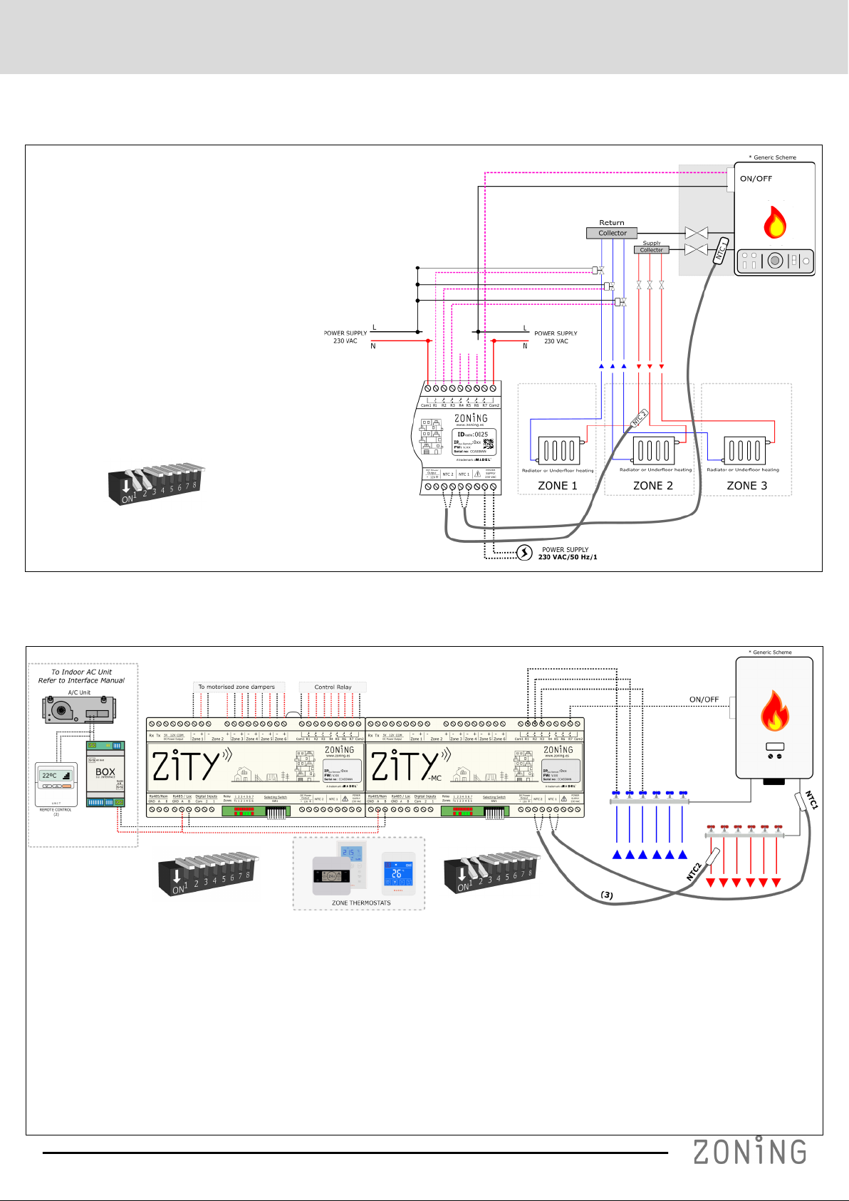
1. Supply voltage, (230VAC/ 50 Hz/
1)
2. 10kOhm NTC temperature sen-
sors (see location according to
type of machine)
3. 12 VDC output voltage for wired
thermostats
4. Control LEDs, to monitor the
status of the control unit
5. 433/434 MHz Radio
transmission antenna (only
in ZITY-RC control units)
6. Digital inputs, potential-free inputs
7. RS485 local communication
bus. For wired thermostats and
expansion modules.
8. RS485 local communication
bus, for communication with
equipment interfaces (connect
in parallel with the previous
bus)
9. RS485 remote communication
bus for home automation com-
munication/ BMS or NetBox
(MODBUS RTU-SLAVE protocol)
10. 24 VDC outputs for control of
motorised zone dampers (maximum
2 dampers per zone) (24Vdc –200
mA)
11. Control relays of the climate-control
equipment (see connection
depending on the type of equipment).
Maximum current 6A
12. Thermostats: Wired or via radio
Fig.1 Connecting all ZONING SYSTEM components in the ZITY control unit.

1.1-A Direct expansion system with via radio thermostats and NetBox gateway
1)
2)
3)

-Direct expansion system with wired thermostats and NetBox gateway.
-
1)
2)
3)

1.1-C Hydronic systems. Fancoil
For the connection of thermostats, motorized dampers and NetBox, Refer to diagrams above.
2– Pipe FANCOIL
Installation
Type Individual Collective Location
NTC 1 Optional*3 Optional*3 Battery inlet
pipe
NTC2 Remove
resistor Optional*3 Battery inlet
pipe
4– Pipe FANCOIL
Installation
Type Individual Collective Location
NTC 1 Optional*3 Optional*3 Heat battery
inlet pipe
NTC2 Optional*3 Optional*3 Cold battery
inlet pipe

1.1-D Radiant system
A Radiant heating installation (radiators or
radiant/ cooling floor) can be zoned.
The system manages the zone thermostatic
valves (ON/OFF) and the switching (ON/OFF)
of the production equipment.
The NTC probes (optional) are used as supply
temperatures protection. NTC1 for the pro-
duction equipment output and NTC2 for the
inlet temperatures to the radiant floor.
To activate in the ZITY the radiant protocol, the
switches must be positioned as follows:
1.1-E Direct Expansion/ Radiant combined hybrid systems
For the connection of thermostats, motorized dampers and NetBox, Refer to diagrams above.

1.2 Power supply
1.3 NTC Probes
DIRECT EXPANSION 1x1 and VRF
Installation type With gateway No gateway Location
NTC 1 Do not connect Do not connect -
NTC2 Leave resistor (1) Advisable or leave resistor Air return
*1: Only install in FUJITSU– GENERAL machines with gateway. The other brands do not require a sensor.
Installation type Individual Collective Location
NTC 1 Optional (3) Optional (3) Battery inlet pipe
NTC2 Remove resistor (4) Optional (3) Battery inlet pipe
FANCOIL 4 PIPES
Installation type Individual Collective Location
NTC 1 Optional (3) Optional (3) Heat battery inlet pipe
NTC2 Optional (3) Optional (3) Cold battery inlet pipe
*3: For fancoil water input temperature protection.
*4: Remove the resistor if a Master thermostat is installed. When using auto-mode detection (no Master), remove the resistor and install the NTC2 sensor in the
water delivery pipe.
RADIANT SYSTEM
Installation type Heating, radiant or cooling floor Location
NTC 1 Optional (5) Boiler output pipe
NTC2 Superficie radiante
*5: For boiler delivery temperature protection.
*6: For input temperature protection in radiant/cooling floor
Optional (6)
-
-

1.4 Installations with more than 6 zones
In installations with more than 6 zones, 1 or 2
zone expansion modules will be connected. The
first expansion module controls zones 7 to 12. A
third module can be added, which will control
from zone 13 to zone 18. These modules
1.6 Control LEDs
The control unit has 2 rows of LEDs (red/green) that are used to monitor its status.
LEDs Colour Description
R1 to R7 Static red
Flashing red
Static red: The associated relay is active (see paragraph 2.11 relays)
Flashing red: Error or learning mode (see error list)
Z1 to Z6
Static red
Static green
Flashing red
Static red: Damper closed
Static green: Damper open
Flashing red: Zone communication error
Tx Random flashing red Flashes every time radio communication arrives
1.7 Control relays
The control unit has 7 control relays. The function of each relay depends on the protocol
chosen in Sw1.
Protocol R1 R2 R3 R4 R5 R6 R7
Direct expansion On/OFF
4 Pipe Fancoil Cold valve Heat valve ON / OFF OFF=Heat
ON= Cool Speed 1 Speed 2 Speed 3
Radiant Zona 1
valve
Zona 2
valve
Zona 3
valve
Zona 4
valve
Zona 5
valve
Zona 6
valve
Boiler
ON/OFF
2 Pipe Fancoil Valve Valve (1) ON / OFF OFF=Heat
ON= Cool Speed 1 Speed 2 Speed 3
1.5 Connecting the motorized dampers. Parallel connection.
Connect the motors of each regulator to wire clamps 1 to 6 on the board (10). Use a red (+) / black (-) wire with a section of be-
tween 0.75 mm2 and 1.0 mm2. If there are two regulators per zone (maximum recommended), connect them in parallel

2 System settings
Configuring the system is a two-step process:
1 Configure the switches of the ZITY control unit: Se lec t s wit ch S W1
ac co rd ing t o th e t yp e of m ac hin e an d po si tio n t he DI P8
in l ear ni ng m od e.
2 Link and configure the thermostats with the control unit
2.2 Configuration and connection of control interfaces
(only for Direct Expansion installations/VRF)
By default, the communication interfaces between the
ZONING System and the Direct expansion climate-
control units are factory-set. Only check the switches to
adjust the unit fan speeds and/ or in the case of remov-
ing the unit remote control. See the all switches configu-
ration of the corresponding interface manual.
The interface is connected to Rs485/LOC Bus, following
the indicated polarity.
For the connection between interfaces and the different
units, see the corresponding manual for each brand.
2.1 Configure the control unit switches: Consult for other applications.
The SW1 switch is used to configure the ZITY control unit according to the type of installation.
Dip 8 from SW1 8 is used to place the unit in learning mode during start-up (see the corresponding section).
2.3.A RC radio thermostat with ZITY-RC: Link the thermostats and the control unit via the following steps:
2.3 Link and configure the thermostats
Access the ZEUS/ ZOE-RC thermostats configuration menus to carry out the steps described. See the following diagrams:
· On the front label, locate the ID number (radio ID) of the ZITY control unit and
associate this number to each of the thermostats.
· Assign a zone number to each thermostat (corresponding to the motorized
control that has been connected to outputs 1 to 6 of the ZITY control unit.
· Select whether the thermostats is Master or Slave. A single thermostat must
be declared as a Master. If there is no Master or more than one, the ZITY con-
trol unit will be in error.

2.3.A ZOE-RC thermostats with ZITY-RC: After locating the corresponding radio ID of the ZITY-RC unit, assign a zone number to each
thermostat and select which thermostat will be MASTER or Slave.
key
2.3.B ZEUS-RC thermostats with ZITY-RC: Assign ID number / Zone / Master– Slave.
Learning and start-up: See section 3 to carry out this process.

2.3.B ZEBRA thermostats with ZITY-W (by wire)
1 Connect the thermostats and the control unit via the following steps:
· For the Master thermostat: define a single Master per installation.
Configure menus 5 (Master/ Slave), 6 (Flexifan), 9 (Actives Modes), 14 (Zone Number) and 16 (Keypad Lock):
For the Slave thermostat: Only configure menus nº5 (Slave) and nº14 (Zone number):
Valid values for the ZEBRA V2 (7 wires) in the case of having a ZEBRA V1 (4 wires) see the advanced setting.
For more information on other menus, see the advanced settings.
Go to menu 5 Access settings
Access the
parameter
Master/Slave:
Place in position 1
Flexifan: Place
in ON position
Go to menu 9
(Actives Modes)
Actives Modes:
Place in position 2
Go to menu 14
(Zone ID)
Access the
parameter
Select the Zone
Number
Go to menu 16
(Type of Locking)
Place in 0 Confirm and Exit
Turn off the
thermostat
Access the parameter
Go to menu 14
(Zone ID)
Access settings Select the zone
number
Confirm and Exit
Access the
parameter
Access the
parameter
Valid values for the ZEBRA V2 (7 wires) in the case of having a ZEBRA V1 (4 wires) see the advanced setting.
For more information on other menus, see the advanced settings.

3 Learning and start-up
In the first place, it is necessary to carry out the appraisal
process in order to detect all the system's elements and
start-up can be carried out later (once recognised).
Place the switches according to the type of the system (Direct
expansion, Fancoil, Boiler…). See page 11
Make sure that DIP 8 is OFF (up).
3.2 Exiting learning modeSalir del modo aprendizaje
1 Wait for 30 seconds after the last component has been
detected.
2 Pull down the DIP8 (ON).
3 Disconnect the voltage to the ZITY
control unit.
3.4 Learning and start-up for systems with zone expansion modules
The learning process should be carried out at the same
time in all the control units, main board (ZITY-RC or ZITY- W)
and expansion modules (ZITY-W/ME).
The SW1 DIP 8 should therefore be placed in learning
mode for all units (central and modules).
The LEDs for the associated zones will be enabled in each
control unit. The main board will detect, apart from the
zones, the expansion modules (LED R2 or LED R2/R3,
OFF).
* For RC systems, enter the ID for the main board in all
thermostats.
3.1 Recognising components
1. Connect the 230VAC power supply
of the ZITY control unit.
2. The control unit is positioned in
learning mode and the 7 LEDs
corresponding to the relays begin
to flash.
3. Every time the thermostat of one of
the zones is recognized by the
control unit, the LED for the zone
lights up in green.
The upper row of LEDs
corresponds to
peripheral detection.
Each time one of them
is detected, the
associated LED goes
out.
LED R1: Pasarela de comunicación máquina.
LED R2: Modulo de expansión 7-12 zonas
LED R3: Modulo de expansión 7-12 zonas
LED R4: Central combinada W-MC
LED R5: Central Slave 1
LED R6: Central Slave 2
LED R7: Central Slave 3
3.3 Start-up in normal operating mode
1 Connect the ZITY control unit again.
2 When power is supplied to the control unit, it will begin
to operate normally according to the settings specified
in the SW1.
3.5 Learning and start-up for systems with combined modules (…-MC). The learning process must be carried out on both
boards (the main one and the combined one), with the following particularities;
3.5.1 ZITY-RC/MC Combined modules: First, check that both
the base board (ZITY-RC) and the combination module
(ZITY-RC/MC) share the same ID.
The thermostats will be detected by both boards, the
gateway (...Box) will only be detected by the base board, and
the ZITY-RC/MC combined module will not be detected in
the relay LEDs although it will normally.
The learning process for the 2 control units can be carried out
at the same time or separately.
If the air and water climate control zones do not coincide,
consult the technical department.
3.5.2 ZITY-W/MC Combined modules:
Carry out the learning process simultaneously in both control
units, base board (ZITY-W) and the combined module (ZITY-W/
MC). The base board will detect the thermostats, the gateway
(…Box) if fitted, and the combined module (LED R4, OFF). The
combined module will not detect any component during this
process.
When starting for the first time in normal mode after learning,
the combined board WILL NOT turn on any LEDs until 3 min
have passed, and will then show the zone LEDs and the relays
that are active.

4 Most common errors
4.1 For all installations:
ERROR INDICATOR CAUSE SOLUTION
1
On supplying 230Vac to
the control unit, no LED
lights up on the control unit
No voltage or no
learning
· Check that voltage is reaching the ZITY
control unit (230VAC ±10%).
· Ensure the learning process has been
carried out.
2 5 minutes after switching
on the control unit, all zone
LEDs start to flash and all
grilles are closed
Incorrect settings · Check the settings of the thermostats.
Make sure that they are to the con-
trol unit.
· Repeat the learning process.
· In Radio systems, check whether it works at
a shorter distance and relocate the antenna.
· In Radio systems, check the operating fre-
quency between thermostats and central are
the same.
3 Some of the zone LEDs do
not light up and the rest do
Learning error · The thermostat corresponding to the
LED switched off has not been recognised
in the learning process.
· Reprogram the thermostat and repeat the
learning process, making sure that all LEDs
light up during the process, waiting for 30s
before finishing.
4 Some of the zone LEDs are
flashing and the dampers of
these zones close
Poor
communication
· The control settings have been changed
since the learning process. Configure it
again.
· Check that the thermostat is in the installa-
tion.
· Check the location and the batteries in
the thermostats via Radio.
· Checking the wiring in the wired thermostats
5 The R7 LED in the relay row
flashes and the zone LEDs
light up in red
More than one
Master
· There are two thermostats declared as
Master in the installation. Re-configure the
thermostats in conflict and leave only one
Master.
6 The control unit does not
show any error but the unit
does not start up
Time programming · Check that the thermostat PROG function
is not enabled and whether it corresponds
to a switch-off time or is not set correctly.
7 The grille closes when it has
to open (and vice versa)
Motors
incorrectly
connected
· Check motor connection. Polarity (black -,
red +).
· Check that ti is tested in the correct operat-
ing mode (Cool/ Heat).
8 One of the grilles is not
working
Zone regulator
connection
· Check motor connection. Polarity (black -,
red +).
· Check that the regulator is not obstructed.
9 All grilles are operating
correctly, but the climate-
control unit does not work
Climate-control
until incorrectly
connected
· Check the control unit settings according to
the type of the equipment.
· Check the connection of the equipment with
the board.

For direct expansion installations:
ERROR INDICATOR CAUSE SOLUTION
1
The R7 LED in the relay row
flashes and the zone LEDs
light up in green
Interface
communication
error
· Check the connection and settings of
the Interface (see manual for each brand
and model).
2 The R2 LED in the relay row
does
not start up
DX mode error · The work mode is not sent. Impose
a thermostat as MASTER and place the con-
trol unit in Local Mode. In the case of
remote systems, check that the mode is
sent by channel Rs485/Rem.
· Check the position of switch 7 of the ZITY or
the active modes of the thermostat, to avoid
not working in radiant modes.
3 The R3 LED in the relay row
is flashing. The system is
blocked
Sensor error · In installations with NO INTERFACE, the
resistor (by default) or the NTC sensor are
not connected. Or the measured
temperature is out of range.
4.3 :
ERROR INDICATOR CAUSE SOLUTION
1
The R6 LED in the relay row
is flashing
Fancoil mode error · The work mode is not sent. Impose a Master
thermostat and place the control unit in Lo-
cal Mode.
In the case of sub-zone, ensure that the
NTC2 sensor is in the delivery.
2 The R7 LED in the relay row
flashes and the R2 and R3
LEDs remain lit
Water temperature
error in Heat mode
· Battery temperature in heat battery out
of range. Check NTC1 connection.
4 The R7 LED in the relay row
is flashing
Combined mode
error
· Check the position of Switch 7 of the ZITY
or Active Modes of the ZEBRA thermostat.
The control unit is attempting to work in
Cool or Radiant Heat Mode.
3 The R7 LED in the relay row
flashes and the R1, R3 and
R4 LEDs remain lit
Water temperature
error in Cool Mode
· Battery temperature in heat battery out
of range. Check connection of NTC1 or
NTC2 for 2T and 4T installations
respectively.

5 ZOE-RC Thermostat advanced settings: ZOE-RC timer-thermostats have an expert menu (Se2) for setting various system
parameters. The parameters that can be configured are shown in the following table:
Parameter Description Values
Fr Radio frequency Fr00 = 433 Mhz; Fr01 = 434 Mhz (*)
Tc Setpoint/ ambient temperature Tc00 = Setpoint temp. (*); Tc01= Ambient +
Hc Active modes (1) Hc00 = Cool/ heat air + DRY+FAN (*)
Hc01 = Cool/ heat air + FAN
Hc02 = Radiant heat / radiant cool
Hc03 = Cool/ heat air + FAN + radiant cool/ heat
Hc04 = Cool/ heat air + DRY + FAN + radiant cool/ heat
Pr Weekly programming Pr00 = No weekly programming
Pr01 = Weekly programming active (*)
Bl Lock modes (1) Bl00 = No lock (*)
Bl01 = Total lock except +/-/ON-OFF
Bl02 = Mode key lock
Bl03 = Mode key lock + Master OFF
Fn Fan Fn00 = Fan inactive (automatic operation)
Min heat temp. Min heat setpoint temperature Selectable from 15 to 21ºC
Max heat temp. Max heat setpoint temperature Selectable from 21 to 30ºC
Min cool temp. Min cool setpoint temperature Selectable from 17 to 25ºC
Max cool temp. Max cool setpoint temperature Selectable from 25 to 30ºC
Hi Hysteresis (1) Hi02 = Hysteresis 0.2ºC (Eu.bac operation)
Hi03 = Hysteresis 0.3ºC
Hi04 = Hysteresis 0.4ºC
Hi05 = Hysteresis 0.5ºC (*)
C-Sp = Hysteresis 0.5ºC and KSP temperature standard
Slv Master/ Slave hybrid mode Slv1 = Mode button active in Slave for temperature limits
Slv0 = Mode button inactive in Slave(*)
(*) Default values
(1) Setting in V04. In previous versions, check active parameters
Carry out the following sequence
to enter the Se2 advanced set-
tings menu: SET, –, ON/OFF
Quick locking keys for ZOE-RC: Use the following key combinations to lock/unlock
the keyboard quickly:
· Bl00 = Unlocking (*)
· Bl01 = All lock except +/-/ON-OFF

6 ZEUS-RC advanced settings: ZEUS-RC thermostat have an expert menu for setting various system parameters.
To access the expert menu, follow this procedure:
Parameter Description Values
Fr Radio frequency Fr = 434 Mhz (*)
Fr = 433 Mhz;
Bl Lock modes (1) OFF = No lock (*)
ON = Menu key lock
Hi Hysteresis (1) Hi02 = Hysteresis 0.2ºC (Eu.bac operation)
Hi05 = Hysteresis 0.5ºC (*)
COMM Communication type BI-DIR = Bidirectional communication(*).(1)
UNI-DIR = Unidirectional communication .(2)
(*) Default values
(1) The bidirectional mode entails a high battery consumption (service life about 1 year)
(2) The unidirectional mode consumes less batteries than bidirectional mode and is indicated when it is not connected with external devices (Netbox) or
for older control units
Parameter Description Values
MODE Active modes 01 = Cool/ heat air + DRY+FAN (*)
02 = Cool/ heat air + FAN
03 = Cool
04 = Radiant heat
05= Radiant heat/ radiant cool
06 = Cool/ heat air + FAN + radiant heat
07 = Cool/ heat air + DRY + FAN + radiant heat
08 = Cool/ heat air + DRY + FAN + radiant heat/ radiant cool

7 ZEBRA Thermostat advanced settings: : The ZEBRA timer-thermostats have a menu for setting various system pa-
rameters. The parameters that can be configured are shown in the following table:
Parameter
ZEBRA V1
Parameter
ZEBRA V2 Description Values
01 01 Weekly programming See user manual
02 02 Time setting See user manual
03 03 Temperature compensation -8ºC a +8ºC (Default=0ºC)
04 04 Backlight On= Backlight always active(*);
OFF=Backlight turns off in 15s
05 05 Master - Slave 0=Slave (*); 1=Master
06 06 Fan-control (in Master only) On=Active; OFF=Disabled (*)
07 07 Factory Reset On= Reset to default values; OFF= Inactive (*)
08 08 ºC/ºF ºC=Celsius (*); ºF= Fahrenheit
· Master thermostat (Place Master in OFF and MODE button 3s):
To access the menu, follow the next steps:
· Slave thermostat (Turn off thermostat and MODE button 3s):
Turn off the
thermostat
Press MODE 3s Programming
menu
Turn off the
thermostat
Press MODE 3s Programming
menu
Note that the menus are different in ZEBRA V1 and ZEBRA V2 (ZEBRA V2 default values are indicated in parentheses).

Parameters
ZEBRA V1
Parameters
ZEBRA V2 Description Values
10 10 Max Cooling setpoint temp. 10 to 30 ºC (default 30ºC)
11 11 Min Cooling setpoint temp. 10 to 30 ºC (default 10ºC)
- 12 Max Heating setpoint temp. 10 to 30 ºC (default 30ºC)
- 13 Min Heating setpoint temp. 10 to 30 ºC (default 10ºC)
12 14 ID (Zone) Zone identifier (1 to 18) (default 01)
13 15 Weekly programming template 07= Programming every day of the week (*);
06= Programming from Monday to Saturday;
05= Programming from Monday to Friday
14 16 Lock options 0= Unlocked;
1= All locked;
2= Lock keys UP - DOWN;
3= Lock MODE key;
4= Lock FAN key;
5= Lock MODO+FAN keys (*);
6= Lock FAN + UP/DOWN keys;
7= Lock FAN + UP/DOWN + MODE keys;
8= Lock UP/DOWN + MODE keys;
15 17 Re-start 0= Re-start disabled; 1=Enabled (starts up in same mode as before
the loos of current) (*)
16 18 Period programming 2/4/6 periods. (Default 4)
- 19 Weekly programming Enabling or disabling weekly programming;
0= Not active; 1= Active
- 20 Digital input 1 0= Not active;1= Window contact;
2= Presence contact; 3= Condensation sensor
- 21 Digital input 2 0= Not active;1= Window contact;
2= Presence contact; 3= Condensation sensor
- 22 Digital input 1 settings 0= Normally closed; 1= Normally open
- 23 Digital input 2 settings 0= Normally closed; 1= Normally open
- 24 ECO Mode 0= Not active; 1= Active
09 09 Active modes 0= Cool air + Fan;
1= Heat air + fan;
2= Cool/ heat air + fan (*);
3= Radiant heat;
4= Radiant cool;
5= Frío + Calor radiante;
6= Air heat + Radiant heat + FAN;
7= Radiant cool + cool air + FAN;
8= Cool/heat air + Cool/heat radiant + FAN;
9= Cool air + FAN + DRY;
10= Cool/ heat air + FAN + DRY;
11= Cool air + cool radiant + FAN + DRY;
12= Cool/ heat air + cool/heat radiant + FAN + DRY
(*) Default values;
ZEBRA V1 = 4-wire thermostat;
ZEBRA V2 = 7-wire thermostat
Other manuals for Zity
2
Table of contents