multicomp pro MP710080 User manual

SWITCHING MODE POWER SUPPLY
MP710079, MP710080 and MP710081


USER MANUAL
Keep this manual in a safe place for quick reference at all times.
This manual contains important safety and operation instructions for correct use of the power
supply. Read through the manual and pay special attention to the markings and labels of this
unit and equipment to be connected.
Pay special attention to these two types of notices used in this manual
WARNING:
Failure to observe this warning may cause injury to persons and damage to power
supply or connected equipment.
CAUTION:
Failure to observe this warning may result in damage to equipment
and Improper functioning of the power supply.
WARNING:
1. Do not use this power supply near water.
2. Do not operate or touch this power supply with wet hands.
3. Do not open the casing of the power supply when it is connected to AC mains.
4. Refer allservicing to qualified service personnel only.
5. Before replacing the AC fuse at AC socket, find out and clear up the cause first.
6. Replace the AC fuse with the same type and rating as the original fuse.
7. The max. output voltage of Model MP710081 is 60VDC, avoid touching the metal contact partof the
output terminals.
CAUTION:
1. Use a grounded 3 pin AC source.
2. This unit is for indoor use only.
3. Do not operate or place this unit in a humid, dusty, in direct sunlight location or near any heat source.
4. Before plugging into local AC mains, check with the rating label at the back of the unit.
5. Do not block any ventilation openings of the unit.
6. This unit must be used within the specified rating, regular excessive continuous loading may cause damage to
the power supply.
7. The gauge size of input power cable must be at least 0.75mm2and the total length of power cable must not
exceed 3m.
OPERATION ENVIRONMENTAL CONDITION
•10-80% R.H.
•Maximum relative humidity 80% for temperature up to 31°C decreasing linearly to 50% relative humidity at
40°C.
•Altitude up to 2000m
•Installation category: CAT 2
•Pollution degree: 2
•Mains supply voltage fluctuation up to ±10% of the normal voltage

1. -
2.
3.
4.
5.
6.
7. -
-
8.
9.
10.
11.
12.
13.
14. -
-
-
15.
16.
17.
Power Switch:
Turns the power supply on–off, when it is on the front display lights up.
AC Input Socket with Fuse
Concealed Fuse box (ply open the cover to get to the fuse)
3.3V/5VDC selection switch (for Aux output 1)
Output Voltage Tuning knob. (Quick push the knob to toggle the coarse and fine tuning)
Output Current Tuning knob. (Quick push the knob to toggle the coarse and fine tuning)
Output On/Off push button
For Main output: Quick push this button to turn the Main output ON/OFF
For Main output & Aux outputs: Push and hold this button for 3 seconds to turn the Main and Aux outputs
OFF, quick push this button again to turn them ON
Main Output Terminal Positive (+) Red color.
Main Output Terminal Negative (-) Black color
Aux Output 1 Terminal Positive (+) Red color (3.3VDC or 5VDC selectable)
Aux Output 1 Terminal Negative (-) Black color (3.3VDC or 5VDC selectable)
Aux Output 2 Terminal Positive (+) Red color (Fixed 12VDC)
Aux Output 2 Terminal negative (-) Black color (Fixed 12VDC)
LCD Display panel showing:
4 digit voltmeter, Ammeter, (CV) constant voltage mode, (CC) constant current mode,
Output Terminal on/off state
2 digit Aux outputs Ammeter
Aux 1 output voltage indicator
USB remote control
Ground Terminal
INTRODUCTION
This series of 100W Switching Mode Power Supplies with Current Limiting Control is designed with the objectives
of high accuracy, compactness and easy portability. Rotary encoder tuning with MCU are used for voltage and
current control. 4 digit display LCD of voltage and current for high precision.
This power supply is ideal for trouble shooting circuit boards or devices which require two or three different input
voltages such as 3V or 5V, 12V and 1-36V. This power supply can provide 3 outputs at the same time.
All three outputs are fully isolated so different cross connections of 2 or 3 outputs can provide various fixed or
variable output voltages. Any output can be connected for positive or negative polarity. (See connection diagrams)
CONTROLS AND INDICATORS

OPERATION
Basic Mode of Operation
This power supply is designed to operate as a constant voltage source or as a constant current source. Automatic
crossover to either mode of operation occurs when the load condition changes as following:
Constant Voltage (CV), Automatic crossover & Constant Current (CC)
The power supply functions as a constant voltage source (CV) as long as the load current is less than the preset
current limiting value. When the load current is equal to or greater than the preset current limiting value, the power
supply will automatically cross over to the constant current mode, voltage will drop, (CC) will show on the LCD
display panel and it will operate as a constant current source.
When the load current drops below the preset current limiting value, the supply returns to constant voltage (CV)
mode.
Set the Output Voltage and Presetting Current Limiting Value (CC)
Turning the voltage or current knob to set your desired values.
Quick pushes on the knobs will move the decimal place for fast tuning.
Turn the knob when the desired number column is flashing otherwise you need to repeat quick pushes again.
One quick push on the current knob to see the preset current limiting value.
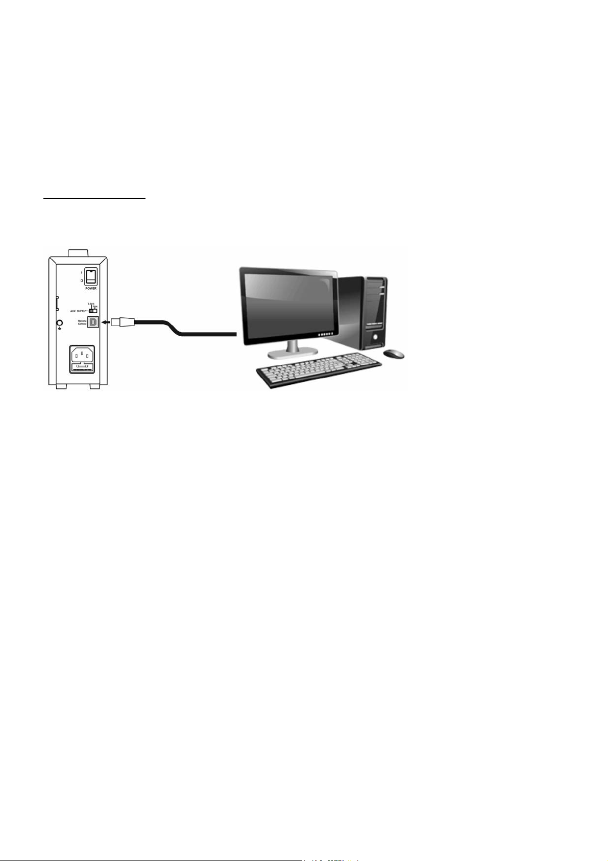
Aux. output 1 voltage selection
Move the switch (4) at the back of power supply for selection of 3.3 or 5 VDC.
At 3.3VDC setting, indicator (15) is Off
and at 5VDC setting indicator (15) is On.
Connection and Operation Procedure
1. Check the rating label and plug in to AC mains.
2. Switch on the power supply and the LCD display should be on at the same time.
3. The (CV) icon should be shown on the display.
4. Turn to current volume knob (6) to maximum clockwise if you do not require lower Current limiting value,
otherwise do the preset the (CC) limiting procedure.
5. Set your desired output voltage and then turn off the output terminal by push button (7).
6. Connect to your load positive to positive and negative to negative.
7. Turn on the output terminal again and check if display shows (CV).
8. If display shows (CC), either your preset current limiting value is too low or your load requires more voltage and
current. You need to re-access the voltage and current requirement of your load and increase the voltage or
current accordingly until (CV) appears.
Connecting the3 outputs (using MP710080 1-36V 3A as an example)
All the three outputs are fully isolated from ground and with each other sothat itispossible to make cross
connections topower a circuit board or device that requires for example: +3 or +5V, +12 Vor -12V and 1-36V as
shown in Fig.1.
The variable main output is set for 12V and itis assigned as the +12V source (available maximum current 3A)
Note the variable main output can be set for other voltage (1-36V) such as 16V.
The fixed 12V is made as the - 12V source (available maximum current 0.5A)
The fixed 5V is made as the +5V source. (available maximum current 0.5A)

DIAGRAM SHOWING CIRCUIT BOARD OR DEVICE
Connecting outputs inseries (using MP710080 as an example)
You can have a 17V fixed output byconnecting the 5V in series with the 12V outputs.
The 2 outputs (Aux.1) can be connected inseries to make a variable 5V to 41V with maximum current 2A (Fig. 2)
The 3 outputs can be connected in series to make a variable 17V to 53V with maximum current 1A,(Fig. 3)
There are other combination of cross connections for different positive and negative output voltages.

Tracking Output Over Voltage Protection (Fault Code F01)
This is to protect the connected load in the event that the output voltage control circuit malfunctions, the maximum
output voltage will not exceed 10% (min. 1.7V) of the adjusted voltage value at the time of the operation.
Protection will be triggered and the output power will be cut off and ouP warning appears as below.
To reset the warning, switch off the unit and remove all loading.
Switch the unit back on again and it should resume normal operation.
If this problem persists, please contact and consult with your agent.
Over Current Protection (Fault Code F02)
Normally the overload protection is sustained by the CC constant current mode.
When the CC mode fails and goes undetected, it may cause serious damage to your test piece or load.
The ocP is to minimize the extent of damage to your loads as power supplies do fail someday.
Switch off your power supply as soon as you see this warning as shown below.
To reset this warning, switch off the unit and remove all loading.
Switch the unit back on again and double check with caution.
If this problem cannot be fixed, please contact and consult with your agent.
Over Temperature Protection (Fault Code F03)
There is a thermo sensor inside the unit to monitor and to prevent the unit to gets too hot inside. At otP, there is no
output and the following warning will appear on the LCD display.
When you get this warning, switch off the unit and remove all loading.
Check your load and output setting. Allow the unit to cool down for at least 30 minutes.
Check if any of the ventilation is blocked, check enough clearance around power supply.
Switch the unit back on again and it should resume normal operation.
If this problem persists, please contact and consult with your agent.

Tracking Output Over Voltage Protection (OVP)
This istoprotect the connected load in the event that the output voltage control circuit malfunctions, the maximum
output voltage will not exceed 30% of the adjusted voltage value at the time of the operation.
Over Temperature Protection
When the temperature inside the power supply becomes higher than a pre-determined value, the output voltage
and current of the power supply will automatically decrease to zero to prevent damage to power supply. When the
temperature inside the power supply returns to normal then the power supply will automatically return to operation
again.
PC CONNECTION
The power supply with USB can be remote control using Windows PC. Connecting the power supply to a PC using
provided USB cable as following connection diagram.
If you need to install a USB driver for power supply connection. Drivers are available to download from the
Farnell product web page.
There are two methods for remote control of the power supply.You can use provided control software or use
your own program with command set provided in this manual.
The PC control software can be downloaded from Farnell product web page.
For the detail usage of driver and PC software. Please refer to PC software manual.
PC software manual is also available to download from the Farnell product web page.

SPECIFICATIONS
MP710080 MP710081
1.0 – 36Vdc 1.0 - 60Vdc
MP710079
100 - 240Vac, 50 / 60Hz
0.83A
1.0 - 20Vdc
0.25 - 5A 0.25 - 3A 0.25 - 1.6A
Input Voltage (Universal input)
Full Load Input Current at 230Vac
Output Voltage Adjustable Range
Output Current Adjustable Range
Voltage Regulation
Load from 10% to 90%Variation 70mV 70mV 70mV
Line from 90 to 264Vac Variation 25mV
≤120mV ≤150mV ≤180mV
Ripple & Noise (peak to peak)
Current Regulation
Load from 10%to 90% Variation 50mA
Line from 90 to 264Vac Variation 20mA
≤50mA
50KHzto 150KHz
Fixed 3.3 /5Vdc,1.8Acont. 2A Max.
Fixed 12Vdc,800mA cont. 1AMax.
≥80.5% ≥80.5%
>0.9
≥80.5%Rotary
Encoder 4 Digit
LCD
5 counts for range V<5V 5 counts for range V<5V 5 counts for range V<5V
±0.2% +5 counts for range V≥5V
15 counts for range I≤1A
±0.5%+6 counts for range I>1A
±0.2% +5 counts for range V≥5V
15 counts for range I≤1A
±0.5%+6 counts for range I>1A
±0.2% +5 counts for range V≥5V
15 counts for range I≤1A
±0.5% +6 counts for range I>1A
Ripple & Noise (peak to peak)
Switching Operation Frequency
Aux output 1
Aux output 2
Power Factor
Efficiency atMaximum Power Volt
and Amp Control Type Voltmeter
and Ammeter Display Voltmeter
Accuracy
Ammeter Accuracy
LCD Indication
Protection
CE Approvals
Cooling System
Dimensions (WxHxD)
Weight
Note:
CC, CV, Amp, Volt, Output ON-OFF,Aux output current
Short Circuit, Overload, Over Temperature, Tracking OVP
LVD: EN 61010, EMC: EN 55011
Natural Convection
70 x 150 x250mm/ 2.8 x6.0 x 9.8in.
2Kgs / 4.4Lbs
All the data are based on 230Vac 50Hz

COMMAND SET
Command code & Return Value
Description
Example
Input Command: SOUT<Output>[CR]
Return Value: [OK][CR]
Set Output on/off
Set Output off: <Output>=0
Set Output on: <Output>=1
Input Command: SOUT0[CR]
Return Value: [OK][CR]
Meaning: Set Output off
Input Command: GOUT [CR]
Return Value: <Output> [CR][OK][CR]
Get Output Status
Output off: <Output>=0
Output on: <Output> =1
Input Command: GOUT[CR]
Return Value: 0[CR][OK][CR]
Meaning: Output is off
Input Command: SETD <VOLTAGE><CURRENT>[CR]
Return Value: [OK][CR]
SET Voltage and Current
<voltage> =0000~3640
<Current> =0000~5100
Input Command:
SETD05001000[CR]
Return Value: [OK][CR]
Meaning: Voltage 5.00V Current
1.000A
Input Command: GETD [CR]
Return Value: <Voltage><;><Current><;>
<CV/CC Mode><;>[CR][OK][CR]
Get display Volt & display Curr &
CV/CC mode
<voltage> =0~9999
<Current> =0~9999
<CV mode> =0 CV Mode
<CC mode> =0 CC Mode
Input Command: GETD [CR]
Return Value:
500;1000;0;[CR][OK][CR]
Meaning: The Display value is
5.00V and 1.000A
It is CV mode
Input Command: GETS [CR]
Return Value: <Voltage><;><Current><;>[CR][OK][CR]
Get Setting Volt & Curr
<voltage> =0~3640
<current> =0~5100
Input Command: GETS[CR]
Return Value:
500;1000;[CR][OK][CR]
Meaning: The Memory setting
voltage value is 5.00V and Current
is 1.000A
Input Command: VOLT<Voltage>[CR]
Return Value: [OK][CR]
Set output voltage
Input Command: VOLT 1000[CR]
Return Value: [OK][CR]
Meaning: Set voltage value is
10.00V
Input Command: CURR<Current>[CR]
Return Value: [OK][CR]
Set output current
Input Command: CURR1000[CR]
Return Value: [OK][CR]
Meaning: Set Current value is
1.000A
Input Command: GVSH [CR]
Return Value: <Voltage>[CR][OK][CR] Get voltage set high limit
<voltage>=???? Input Command: GVSH [CR]
Return Value: 3600 [CR][OK][CR]
Meaning: voltage set high limit is
36.00V
Input Command: GVSL [CR]
Return Value: <Voltage>[CR][OK][CR] Get voltage set low limit
<voltage>=??? Input Command: GVSL [CR]
Return Value: 100 [CR][OK][CR]
Meaning: Voltage set low limit is
1.00V
Input Command: GISH [CR]
Return Value: <Current>[CR][OK][CR] Get current set high limit
<Current>=???? Input Command: GISH [CR]
Return Value: 5500 [CR][OK][CR]
Meaning: Current set high limit is
5.500A
Input Command: GISL [CR]
Return Value: <Current>[CR][OK][CR] Get current set low limit
<Current>=??? Input Command: GISL [CR]
Return Value: 250 [CR][OK][CR]
Meaning: Current set low limit is
0.250A
Input Command: GMAX [CR]
Return Value: <Voltage><;><Current><;>[CR][OK][CR] Get voltage set high limit & current
set high limit
<voltage> =????
<current> =????
Input Command: GMAX [CR]
Return Value:
3600;5500;[CR][OK][CR]
Meaning: Voltage set high limit is
36.00V & Current set high limit is
5.500A
Input Command: GMIN [CR]
Return Value: <Voltage><;><Current><;>[CR][OK][CR] Get voltage set low limit & current
set low limit
<voltage> =???
<current> =???
Input Command: GMIN [CR]
Return Value:
100;250;[CR][OK][CR]
Meaning: Voltage set low limit is
1.00V & Current set low limit is
0.250A


Made in China
INFORMATION ON WASTE DISPOSAL FOR CONSUMERS OF ELECTRICAL & ELECTRONIC
EQUIPMENT.When this product has reached the end ofits life itmust be treated asWaste
Electrical & Electronics Equipment (WEEE). Any WEEE marked products must not bemixed with
general household waste, but kept separate for the treatment, recovery and recycling of the
materials used. Contact your local authority for details ofrecycling schemes in your area.
This manual suits for next models
2
Table of contents
Other multicomp pro Power Supply manuals