Conduct Length Measurement
You can conduct length measurement by using reflective sensor (default
etting) for I-Mark media roll or transmissive sensor for gap label roll.s
Please refer to the VersaJet Programming Reference for changing the sensor
from reflective to transmissve, if the gap label roll is used.
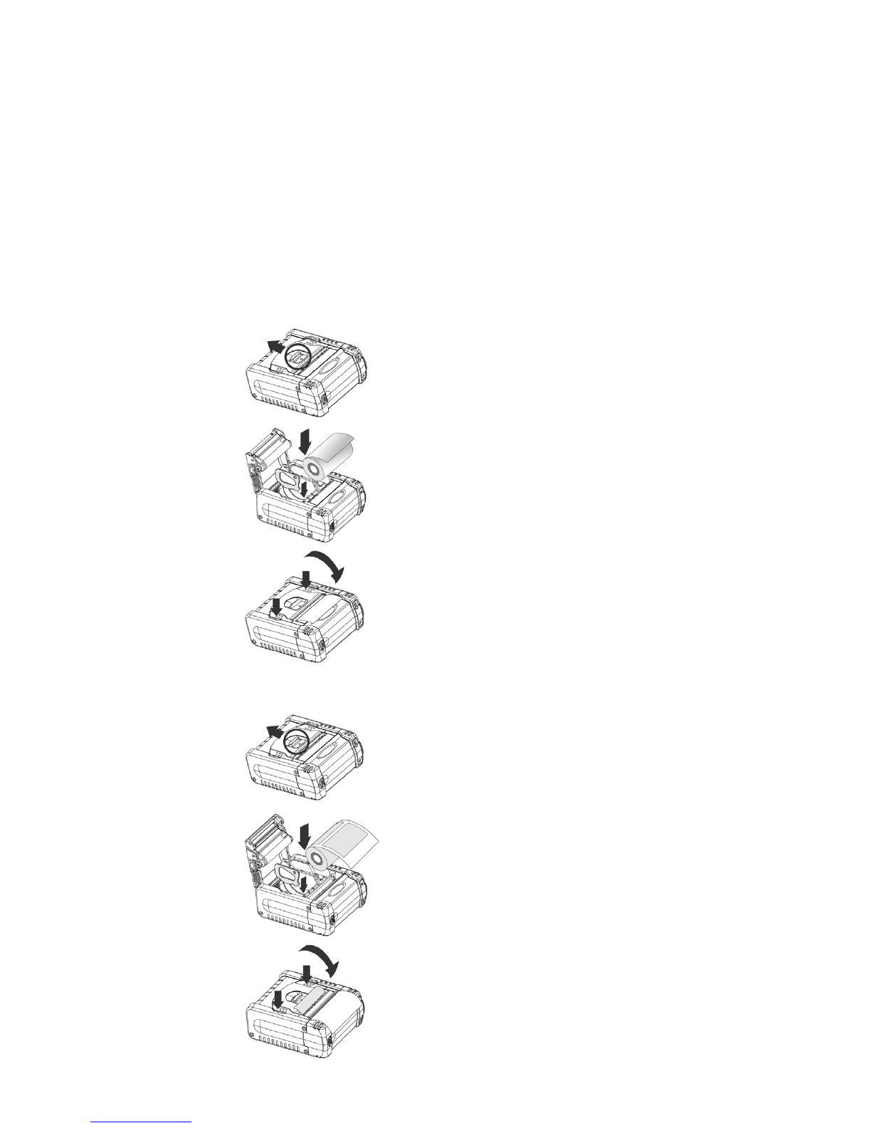
1. Open the media compartment cover, the LED1 will light up orange, and
LED2, LED3 will light up green respectively, and then start flashing after 10
seconds.
2
. Load the media roll.
3
. Press the FEED button and release it.
4. Close the media compartment cover, the LED3 flashes green 3 times. The
Micro2 will feed several labels to execute length measurement. After the
length measurement is completed, the Micro2 will be ready in the next
printing position and the LED1 will flash green at 2 seconds intervals.
If the length measurement is failed or executed without setting the correct
media roll, the Micro2 will issue a paper jam error. Please conduct length
measurement once again. On condition that the length measurement is done
successfully, the value will be stored into the flash memory. When you load
the same media roll next time, the Micro2 will perform top-of-form by feeding
one label or one measured length of the receipt paper right after you close the
edia compartment cover in power-on state.m
The Micro2 will also feed one label or one measured length of the receipt
paper while pressing the FEED button. However, if you load a different media
roll, you will have to re-conduct length measurement.
Revert to Standard Mode
The printing mode will be switched to page mode after the length
measurement is completed. If you would like to revert it to standard mode,
please follow the steps indicated below:
1. Open the media compartment cover, the LED1 will light up orange, and
LED2, LED3 will light up green respectively, and then start flashing after 10
seconds.
2. Load the receipt roll (without I-Mark), then press the FEED button and
release it.
3. Close the media compartment cover, the LED3 flashes green 3 times. The
Micro2 will feed about 16 cm receipt paper and remain ready for the next
printing position. The Micro2 will give two beeps, the LED1 and LED2 will
light up orange and green respectively.
4. Press “FEED” button, the LED1 of Micro2 will flash green at 2 seconds
intervals.
5. The Micro2 is now ready for standard mode operation.
4